Mitsubishi Electric MXZ-4A71VA Installation Manual
Floor type air conditioners
Hide thumbs
Also See for MXZ-4A71VA:
- Service manual (192 pages) ,
- Installation manual (9 pages) ,
- Installation manual (100 pages)
Table of Contents
Advertisement
Available languages
Available languages
Quick Links
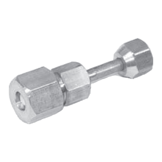
Joint Pipe
Photo
Dimensions
How to Use / How to Install
Make sure that you have all the following parts, in addition to this manual in this box:
Joint Pipe
PAC-SG76RJ-E (unit side: 9.52 diameter, onsite pipe side: 15.88 diameter)
PAC-493PI (unit side: 6.32 diameter, onsite pipe side: 9.52 diameter)
MAC-A454JP-E (unit side: 9.52 diameter, onsite pipe side: 12.7 diameter)
MAC-A455JP-E (unit side: 12.7 diameter, onsite pipe side: 9.52 diameter)
MAC-A456JP-E (unit side: 12.7 diameter, onsite pipe side: 15.88 diameter)
Unit side
Apply flare processing to onsite pipes to adapt to R410A, according to the table on the right.Use optional accessory flare nut at this time.
Check the installation manual attached to the outdoor unit for advisability on whether or not onsite (existing) pipes can be used.
B
Pipe diameter
(mm)
6.35 1/4
9.52 3/8
dies
12.70 1/2
Copper pipe
15.88 5/8
2 Remove caps (both ends) for protection against
mixing of foreign materials from optional part,
and thinly apply refrigerat or oil
(locally procured) on flare surface.
Refrigerator oil application point
Apply refrigerator oil to entire circumference of
flare sheet surface.
Do not apply to thread section.
(If applied to threads, flare nut can easily
be loosened.)
E-166
Unit 9.52
Pipe 12.7
* photo model: PAC-493PI
Unit : mm (inch)
Onsite piping side
B size (mm)
R410A flare tool R22/R407C flare tool
Clutch type
0〜0.5
1.0〜1.5
0〜0.5
1.0〜1.5
0〜0.5
1.0〜1.5
0〜0.5
1.0〜1.5
3 Securely tighten flare nut using torque
wrench according to the table on the right.
〈Proper tightening torque using torque wrench〉
Outer diameter of
copper pipe (mm)
12.70
15.88
Descriptions
A part to connect refrigerant pipes of the different diameter.
(Unit 9.52 → 12.7)
Applicable Models
MXZ-3A54VA
MXZ-4A71VA
MXZ-4A80VA
Specifications
9.52
Pipe diameter
Pipe material
C 1220T - OL
Installation procedure
(carefully read the following before installing.)
This optional part is used to connect indoor/outdoor unit to
onsite pipes of different diameters.
When installing this optional part, be sure to read
Refrigerant pipe connection in the installation manual
attached to outdoor unit.
When flare processing for
Outer diameter of
refrigerant R410A is applied
copper pipe ( mm)
using current tool, refer to
6.35
the table above. B size can
9.52
be secured using copper
pipe gauge for margin
12.70
15.88
adjustment.
Tightening torque N ・ m
(kgf ・ cm)
14〜18 ( 140〜180)
6.35
34〜42 ( 340〜420)
9.52
49〜61 ( 490〜610)
68〜82 ( 680〜820)
MAC-A454JP-E
MXZ-5A100VA
PAC-AK50BC
MXZ-8A140VA
PAC-AK30BC
Processing size of
Flare shape
flare section (mm)
8.7〜9.1
45゜± 2゜
12.8〜13.2
16.2〜16.6
R0.4〜R0.8
19.3〜19.7
4 After refrigerant pipe is connected,
be sure to perform gas leakage
inspection for onsite connection
pipes (including this optional part)
and indoor/outdoor unit.
5 Heat insulation is necessary for
this optional part: Wrap heat insulator
(locally procured) around the onsite
pipes and also the optional part
(for dewdrop dripping prevention).
6 Perform test run according to the
installation manual of the unit,
making sure to also perform ope-
ration check.
Advertisement
Table of Contents

Related Manuals for Mitsubishi Electric MXZ-4A71VA


Summary of Contents for Mitsubishi Electric MXZ-4A71VA
- Page 1 Pipe 12.7 Descriptions Photo A part to connect refrigerant pipes of the different diameter. (Unit 9.52 → 12.7) Applicable Models MXZ-3A54VA MXZ-5A100VA PAC-AK50BC MXZ-4A71VA MXZ-8A140VA MXZ-4A80VA PAC-AK30BC Specifications 9.52 Pipe diameter Pipe material C 1220T - OL * photo model: PAC-493PI...
- Page 2 FLOOR TYPE AIR CONDITIONERS MFZ-KJ09NA MFZ-KJ12NA MFZ-KJ15NA MFZ-KJ18NA For INSTALLER INstAllAtIoN MANuAl English • When installing multi units, refer to the installation manual of the multi unit for outdoor unit installation. PARA EL INSTALADOR MANuAl DE INstAlACIÓN Español • Al instalar unidades múltiples, consulte el manual de instalación de la unidad múltiple para obtener información sobre la instalación de la unidad exterior.
-
Page 3: Table Of Contents
Required Tools for Installation CONTENTS Tube benders 5/32 in. (4 mm) hexagonal 5. PURGING PROCEDURES, LEAK TEST, Phillips screwdriver wrench 1. BEFORE INSTALLATION ......1 AND TEST RUN ........10 Level Flare tool for R410A 2. INDOOR UNIT INSTALLATION .....4 6. PUMPING DOWN ........10 Scale Gauge manifold for R410A 3. OUTDOOR UNIT INSTALLATION ..8 Utility knife or scissors Vacuum pump for R410A When installing multi units, refer to the 4. FLARE CONNECTION, PIPE 3 in. (75 mm) hole saw Charge hose for R410A installation manual of the multi unit for CONNECTION ........9 Torque wrench Pipe cutter with reamer outdoor unit installation. Wrench (or spanner) 1. BEFORE INSTALLATION 1-1. - Page 4 1-2. SELECTING THE INSTALLATION LOCATION INDOOR UNIT Note: Note: In rooms where inverter type fluorescent lamps are • Where airflow is not blocked. When operating the air conditioner in low outside used, the signal from the wireless remote controller • Where air spreads over the entire room. temperature, be sure to follow the instructions may not be received. • Rigid wall and flat floor without vibration. described below. • Where it is not exposed to direct sunlight. Do not OUTDOOR UNIT • Never install the outdoor unit in a place where its air expose to direct sunlight also during the period fol-...
- Page 5 1-4. INSTALLATION DIAGRAM ACCESSORIES Use the wall hole Wall hole cover (D) Check the following parts before installation. sleeve (C) to Indoor unit <Indoor unit> Seal the wall hole prevent indoor/ gap with putty (H). (1) Drain hose *1 outdoor connect- Wall hole ing wire (A) from (2) Remote controller holder Attach the pipe sleeve (C) contacting metal (3) Screws for (2) 3.5 × 16 mm (Black) to wall with pipe at- parts in the wall tachment strap (E). (4) Pipe cover and to protect (5) Band the wiring from Cut off the Pipe attachment (6) Battery (AAA) for (12) rodents. extra length. strap (E) (7) Indoor unit mounting bracket (8) Fixing screws for (7) 4 × 25 mm Attachment screw (F) (9) Wood screw for indoor unit fixation...
-
Page 6: Indoor Unit Installation
2. INDOOR UNIT INSTALLATION 2-1. FIXING OF INDOOR UNIT MOUNTING BRACKET • Find a structural material (such as a stud) in the wall and fix bracket (7) horizontally with fixing screws (8). • To prevent bracket (7) from vibrating, be sure to install the fixing screws in the holes indicated in the illustration. For added support, fixing screws may also be installed in other holes. 2-2. HOLE DRILLING Wall 1) Determine the wall hole position. 2) Drill a ø3 in. (ø75 mm) hole. The outdoor side should be 6/32 to 9/32 in. (5 to ø3 in.(ø75 mm) 6/32 - 9/32 in. 7 mm) lower than the indoor side. (5 - 7 mm) 3) Insert wall hole sleeve (C). Indoor Outdoor side side HOLE POSITIONS FOR REAR OR LEFT-REAR PIPING FOR RIGHT DOWNWARD OR LEFT DOWN- FOR LEFT PIPING FOR RIGHT PIPING (The following figure is a front view WARD PIPING of the indoor unit installation location.) (The following figure is a view of the bottom of inch (mm) the indoor unit from above.) - Page 7 2-4. INDOOR UNIT INSTALLATION 2-4-1. INSTALLING THE INDOOR UNIT ON THE FLOOR 27-3/4 (705) inch (mm) 1. Place the indoor unit on the flat floor. 2. Fix the indoor unit at 4 points with the included wood screws (9) and washers (10). Tighten the screws securely. 2-4-2. MOUNTING THE INDOOR UNIT ON THE WALL 1. Hook the top of the indoor unit on the indoor unit mounting bracket (7). 2. Fix the indoor unit at 4 points with the included wood screws (9) and washers (10). Tighten the screws securely. 2-4-3. EMBEDDING THE INDOOR UNIT IN A WALL 1. Make a hole in the wall. 2. Using reinforcement material, adjust the depth. 3. Remove 6 screws that fix the base to the unit. Remove the base from the unit. 4. Fix the indoor unit at 4 points with the included wood screws (9) and washers Unit (10). Tighten the screws securely. Reinforcement material Base 2-5. PIPE FORMING AND INSTALLATION Note: Refer to 4. FLARE CONNECTION, PIPE CONNECTION. Piping Refrigerant piping Push Piping bent outward tape Pipe Forming • Route the drain hose diagonally below the connecting pipes.
- Page 8 2-6. CONNECTING WIRES FOR INDOOR UNIT Note: When the indoor unit is powered from the outdoor unit, depending on local code, a disconnect switch needs to be installed to a power supply circuit. 1) Remove the electrical cover. 2) Remove the conduit plate. 3) Attach the conduit pipe to the conduit plate with the lock nut. The indoor/outdoor unit connecting wire (A) appearing from the inside of conduit pipe should be less than 7/8 in. (23 mm). (Fig. 1) 4) Process the end of ground wire (Fig. 2). Connect it to the ground terminal of the electrical parts box. 5) Process the end of indoor/outdoor unit connecting wire (A) (Fig. 2). Attach it to the terminal block. Be careful not to make mis-wiring. Attach the wire to the terminal block securely so that its core cannot be seen, and no external force affects the connecting section of the terminal block. 6) Firmly tighten the terminal screws. After tightening, verify that the wires are tightly fastened. 7) Reinstall the conduit plate. 8) Reinstall the electrical cover. INDOOR UNIT Grounding Terminal block Remark: Conduit pipe terminal** * A disconnect switch (15A MAX) should be required. Pipe Check the local code. cover Disconnect ** Use a ring tongue terminal switch* in order to connect a ground 208/230 VAC wire to terminal. 1 phase, 60 Hz OUTDOOR UNIT Power supply 208/230 VAC, 1 phase 2 wires.
- Page 9 2-8. FRONT PANEL INSTALLATION 1) Open the rear horizontal vane. 2) Attach the panel. Make sure that the catches are engaged. 3) Fix the panel with screws. 4) Insert the bottom part of the front panel. 5) Push 3 places on the upper part of the front panel to close it. Panel Indoor unit Front panel Indoor unit Panel Rear horizontal vane 2-9. CONNECTING AN INTERFACE (option)/CONNECTOR CABLE (option) TO THE AIR CONDITIONER • Connect an interface/connector cable to the indoor control P.C. board of Thin part of the connecting cable. an air conditioner with a connecting cable. Place this part where customers • Cutting or extending the connecting cable of the interface/connector ca- cannot touch it. ble results in defects in connecting. Do not bundle the connecting cable Room air together with power supply cord, indoor/outdoor connecting wire, and/or conditioner Main body of an interface earth wire. Keep as much distance as possible between the connecting cable and those wires.
-
Page 10: Outdoor Unit Installation
3. OUTDOOR UNIT INSTALLATION 3-1. CONNECTING WIRES FOR OUTDOOR UNIT 1) Remove the service panel. 2) Remove the conduit cover. 3) Attach the conduit connectors to the conduit plate with lock nuts then secure it against unit with screws. 4) Connect the ground wires of indoor/outdoor unit connecting wire (A) and power 19/32 in. supply cord (L) to the TB support. L1 L2 (15 mm) 5) Loosen the terminal screws, then attach indoor/outdoor unit connecting wire (A) and power supply cord (L) from the indoor unit correctly to the terminal block. Attach the wires to the terminal block securely so that the cores cannot be seen, and no external force affects the connecting section of the terminal Power supply cord (L) Lead block. wire 6) Firmly tighten the terminal screws. After tightening, verify that the wires are tightly fastened. 7) Install the conduit cover. 8) Install the service panel securely. <KJ09/12> • Make earth wire a little longer than others. (More than 4 in. [100 mm]) • For future servicing, leave some slack in the connecting wires. • Be sure to attach each screw to its correspondent terminal when securing the cord and/or the wire to the terminal block. -
Page 11: Flare Connection, Pipe Connection
4. FLARE CONNECTION, PIPE CONNECTION 4-1. FLARE CONNECTION 1) Cut the copper pipe as straight as possible with a pipe cutter. (Fig. 1, 2) 2) Remove all burrs from the cut section of the pipe, ensuring that precautions Good No good are taken to avoid getting metal shavings into the piping. (Fig. 3) 90° 3) Remove flare nuts attached to indoor and outdoor units, then put them on Copper pipe. pipe 4) Flaring work (Fig. 4, 5). Firmly hold copper pipe in the dimension shown in the table. Select A inch (mm) from the table according to the tool you use. Tilted Uneven Burred 5) Check Fig. 1 Fig. 2 • Compare the flared work with Fig. 6. • If flare is defective, cut off the section and repeat procedure. Copper pipe Burr A inch (mm) Tightening torque Spare reamer Pipe B inch Clutch Clutch Wing nut Pipe cutter diameter ft-lb (mm) type tool type tool type tool N•m... -
Page 12: Purging Procedures, Leak Test, And Test Run
5. PURGING PROCEDURES, LEAK TEST, AND TEST RUN 5-1. PURGING PROCEDURES AND LEAK TEST 5-2. TEST RUN 1) Remove service port caps from stop valves on both sides of refrigerant lines. 1) Insert power supply plug into the power outlet and/or (The stop valves are fully closed when shipped.) Leave closed. turn on the breaker. 2) Connect gauge manifold to ports of stop valves. 2) Press the E.O. SW once for COOL, and twice for HEAT operation. Test run will be performed for 30 minutes. If the left lamp of the operation indicator blinks every 0.5 Stop valve cap Compound pressure –14.7 psi [Gauge] seconds, inspect the indoor/outdoor unit connecting (Torque 15 to gauge (for R410A) *4 to 5 turns (–0.101 Mpa) 22 ft-lb, 19.6 to wire (A) for mis-wiring. After the test run, emergency Pressure gauge *Close 29.4 N•m, 200... - Page 13 Herramientas necesarias para la instalación ÍNDICE 5. PROCEDIMIENTOS DE PURGADO, Dobladoras de tubos Llave hexagonal de 5/32 PRUEBA DE FUGAS Y FUNCION- Destornillador Phillips pulg. (4 mm) 1. ANTES DE LA INSTALACIÓN ....1 AMIENTO DE PRUEBA ...... 10 Nivel Abocardador para R410A 2. INSTALACIÓN DE LA UNIDAD 6. BOMBEO DE VACIADO ..... 10 Báscula Válvula colectora de manó- INTERIOR ..........4 Cuchilla o tijeras metro para R410A 3. INSTALACIÓN DE LA UNIDAD Al instalar unidades múltiples, consulte Broca para serrar de 3 pulg. (75 mm) Bomba de vacío para R410A EXTERIOR .
- Page 14 1-2. SELECCIÓN DEL LUGAR DE INSTALACIÓN UNIDAD INTERIOR Nota: Nota: En habitaciones con fluorescentes de tipo inversor, • Donde no se obstaculice el flujo de aire. Si utiliza el acondicionador de aire cuando la tem- puede que la señal del controlador remoto inalámbrico • Donde el aire se pueda propagar por toda la habi- peratura exterior sea baja, observe las instruccio- no se reciba. tación. nes siguientes. • Pared rígida y suelo plano sin vibraciones. UNIDAD EXTERIOR • No instale nunca la unidad exterior en un • Donde no esté expuesto a la luz solar directa.
- Page 15 1-4. DIAGRAMA DE INSTALACIÓN ACCESORIOS Utilice el man- Cubierta del orificio de la pared (D) Antes de la instalación, compruebe que tiene las siguientes piezas. guito del orificio <Unidad interior> Unidad Selle el hueco de la de la pared (C) interior pared con masilla (H). (1) Manguera de drenaje *1 para impedir que (2) Soporte del controlador remoto los cables de co- Manguito del Fije la tubería a la pared orificio de la nexión interiores/ (3) Tornillos para (2) 3,5 × 16 mm (negro) con la abrazadera de pared (C) exteriores (A) sujeción de la tubería (E). (4) Recubrimiento del tubo estén en contacto (5) Banda con las piezas Corte la exten- Abrazadera de (6) Batería (AAA) para (12) metálicas de la sión sobrante.
- Page 16 2. INSTALACIÓN DE LA UNIDAD INTERIOR 2-1. FIJACIÓN DEL SOPORTE DE MONTAJE DE LA UNIDAD INTERIOR • Localice un elemento estructural en la pared (como un pilar) y fije el soporte (7) horizontalmente con tornillos de fijación (8). • Para evitar que vibre el soporte (7), asegúrese de colocar los tornillos de fijación en los orificios que se indican en la ilustración. Si desea una mayor fijación, pue- de instalar también tornillos en otros orificios. Pared 2-2. TALADRADO DE ORIFICIOS ø3 pulg. (ø75 mm) 1) Determine la posición de los orificios en la pared. 6/32-9/32 pulg. (5-7 mm) 2) Perfore un orificio de 3 pulg. (75 mm) de diámetro. El lado exterior debe quedar entre 6/32 y 9/32 pulg. (5 y 7 mm) más bajo que el lado interior. Lado Lado 3) Inserte el manguito del orificio de la pared (C). interior exterior POSICIONES DE LOS ORIFICIOS PARA TUBERÍAS POSTERIOR O POSTE- PARA TUBERÍAS DERECHA O IZQUIERDA TUBERÍA IZQUIERDA...
- Page 17 2-4. INSTALACIÓN DE LA UNIDAD INTERIOR pulgadas (mm) 2-4-1. INSTALACIÓN DE LA UNIDAD INTERIOR EN EL SUELO 27-3/4 (705) 1. Coloque la unidad interior sobre una superficie plana. 2. Fije la unidad interior por 4 puntos con los tornillos para madera (9) y las arandelas (10) que se proporcionan. Apriete firmemente los tornillos. 2-4-2. MONTAJE DE LA UNIDAD INTERIOR EN LA PARED 1. Enganche el extremo superior de la unidad interior en el soporte de montaje de la unidad interior (7).
- Page 18 2-6. CABLES DE CONEXIÓN PARA LA UNIDAD INTERIOR Nota: Cuando la alimentación de la unidad interior procede de la unidad exterior, en función del código local, se debe instalar un interruptor de desconexión en el circuito de alimentación. 1) Retire la cubierta eléctrica. 2) Retire la placa de conducción. 3) Una la tubería de conducción a la placa de conducción con la tuerca de fijación. El cable de conexión de la unidad interior/exterior (A) que procede desde el inte- rior de la tubería de conducción debe ser menor de 7/8 pulg. (23 mm). (Fig. 1) 4) Procese el extremo del cable de tierra (Fig. 2). Conéctelo al terminal de tierra de la caja de piezas eléctricas. 5) Procese el extremo del cable de conexión de la unidad interior/exterior (A) (Fig. 2). Conéctelo al panel de terminales. Procure no equivocarse al hacer las conexio- nes. Fije con firmeza el cable al panel de terminales de modo que no quede a la vista ninguna de sus piezas internas y que ninguna fuerza externa afecte a la sec- ción de conexión del panel de terminales. 6) Apriete bien los tornillos de los terminales. Una vez apretados los tornillos, compruebe que los cables estén bien fijados. 7) Vuelva a instalar la placa de conducción. 8) Vuelva a instalar la cubierta de la instalación eléctrica. Observación: UNIDAD INTERIOR Tubería de * Es posible que se requiera un Terminal de conducción Panel de terminales interruptor de desconexión tierra** Recu- (MÁX. 15 A). brimien- Consulte la normativa local. to del ** Utilice un terminal en anillo Interruptor de tubo para conectar el cable de...
- Page 19 2-8. INSTALACIÓN DEL PANEL FRONTAL 1) Abra el deflector horizontal posterior. 2) Instale el panel. Asegúrese de que los cierres quedan ajustados. 3) Fije el panel con tornillos. 4) Inserte la parte inferior del panel frontal. 5) Presione en las 3 posiciones de la parte superior del panel central para cerrarlo. Panel Unidad interior Panel frontal Unidad interior Panel Deflector hori- zontal posterior 2-9. CONEXIÓN DE UNA INTERFAZ (opcional) O UN CABLE CONECTOR (opcional) AL ACONDICIONADOR DE AIRE Parte delgada del cable de • Conecte una interfaz/un cable conector a la placa de circuito impreso Acondicio- conexión. Colóquela donde los interior del acondicionador de aire mediante un cable de conexión. nador de clientes no puedan tocarla. • Si corta o empalma el cable de conexión de la interfaz o el cable conec- aire de sala Cuerpo principal de una interfaz...
- Page 20 3. INSTALACIÓN DE LA UNIDAD EXTERIOR 3-1. CABLES DE CONEXIÓN PARA LA UNIDAD EX- TERIOR 1) Extraiga el panel de servicio. 2) Extraiga la cubierta de conducción. 3) Acople los conectores de conducción a la placa de conducción con las tuer- cas de bloqueo y, a continuación, fíjelo a la unidad con tornillos. 19/32 plug. 4) Conecte los cables de tierra del cable de conexión de la unidad interior/ L1 L2 (15 mm) exterior (A) y el cable de alimentación (L) a la fijación TB. 5) Afloje los tornillos del terminal, y luego conecte correctamente el cable de conexión de la unidad interior/exterior (A) y el cable de alimentación (L) de la unidad interior al panel de terminales. Fije con firmeza los cables al pa- Cable de alimentación (L) Cable nel de terminales de modo que no quede a la vista ninguna de sus piezas...
- Page 21 4. CONEXIÓN ABOCARDADA, CONEXIÓN DE TUBERÍA 4-1. CONEXIÓN ABOCARDADA 1) Corte el tubo de cobre correctamente con un cortador de tubos. (Fig. 1, 2) 2) Elimina las rebabas de la sección de corte de la tubería, asegurándose de tomar Bien precauciones para evitar la entrada de recortes metálicos en la tubería. (Fig. 3) 90° 3) Extraiga las tuercas abocardadas colocadas en las unidades interior y exte- Tubería rior y póngalas en el tubo. de cobre 4) Labores de abocardamiento (Fig. 4, 5). Sujete firmemente el tubo de cobre de la dimensión que se muestra en la tabla. Seleccione A pulgadas (mm) en la tabla según la herramienta que emplee. Inclinado Irregular Con rebabas 5) Compruebe Fig. 1 Fig. 2 • Compare el abocardado con la Fig. 6. • Si el abocardado es defectuoso, corte la sección y repita el procedimiento. Tubería de cobre Rebaba A en pulgadas (mm)
- Page 22 5. PROCEDIMIENTOS DE PURGADO, PRUEBA DE FUGAS Y FUNCIONAMIENTO DE PRUEBA 5-1. PROCEDIMIENTO DE PURGADO Y PRUEBA DE 5-2. FUNCIONAMIENTO DE PRUEBA FUGAS 1) Inserte el enchufe de la alimentación en la toma de corriente y/o encienda el disyuntor. 1) Retire las tapas de la abertura de servicio de las válvulas de retención si- 2) Pulse el interruptor E.O. SW una vez para el funcionamiento tuadas a ambos lados de las líneas de refrigerante. (La unidad se suminis- de REFRIGERACIÓN (COOL), y dos veces para el funcio- tra con las válvulas de retención completamente cerradas). Debe dejarlas namiento de CALEFACCIÓN (HEAT). El funcionamiento de cerradas.
- Page 23 Outils nécessaires à l’installation TABLE DES MATIERES Cintreuse de tubes Clé à ouverture fixe (ou clé simple) 5. PROCEDURES DE PURGE, TEST 1. AVANT L’INSTALLATION ...... 1 DE CONTROLE DES FUITES ET Tournevis Phillips Clé hexagonale de 5/32 in. (4 mm) 2. INSTALLATION DE L’UNITE ESSAI DE FONCTIONNEMENT ..10 Niveau Outil d’évasement pour le modèle R410A INTERNE ..........4 6. PURGE ..........10 Règle graduée Collecteur à jauge pour le modèle R410A 3. INSTALLATION DE L’UNITE Couteau tout usage ou paire de ciseaux Pompe à vide pour le modèle R410A Lors de l’installation de plusieurs unités, EXTERNE ..........8 reportez-vous au manuel d’installation corres- Scie-cloche de 3 in. (75 mm) Tuyau de charge pour le modèle R410A 4. RACCORDS A EVASEMENT, RAC-...
- Page 24 1-2. CHOIX DE L’EMPLACEMENT D’INSTALLATION UNITE INTERNE Remarque : Remarque : L’unité interne peut ne pas recevoir les signaux de Il est conseillé de faire une boucle avec le tuyau • Emplacement favorisant la circulation de l’air. la télécommande dans une pièce dont le système le plus près possible de l’unité externe de façon à...
- Page 25 1-4. SCHEMA D’INSTALLATION ACCESSOIRES Utilisez le man- Cache d’ouverture murale (D) Vérifiez les pièces suivantes avant l’installation. chon d’ouverture Unité <Unité interne> Bouchez l’ouverture murale (C) pour interne murale avec du mastic (H). (1) Tuyau de vidange *1 éviter tout contact Manchon entre le câble (2) Support de la télécommande d’ouverture Fixez le tuyau au mur de connexion de (3) Vis (2) de 3,5 × 16 mm (noires) murale (C) à l’aide d’une bande de l’unité interne/ fixation de tuyau (E). (4) Gaine du tuyau externe (A) et les (5) Collier pièces métal- Coupez Bande de fixation liques du mur ou (6) Pile (AAA) pour (12) l’excédent.
- Page 26 2. INSTALLATION DE L’UNITE INTERNE 2-1. INSTALLATION DU SUPPORT DE FIXATION DE L’UNITE INTERNE • Repérez un matériau de structure (comme un goujon) dans le mur et fixez le support (7) horizontalement à l'aide de vis de fixation (8). • Pour éviter toute vibration du support (7), veillez à installer les vis de fixation dans les trous indiqués sur l’illustration. Pour obtenir un support supplémentaire, vous pouvez également poser des vis de fixation dans d’autres trous. 2-2. PERCEMENT D’UNE OUVERTURE 1) Déterminer la position de l’ouverture murale. ø3 in. (ø75 mm) 2) Percez un orifice de 3 in. (75 mm) de diamètre. Le côté extérieur 6/32-9/32 in. (5-7 mm) doit être 6/32 à 9/32 in. (5 à 7 mm) plus bas que le côté intérieur. 3) Insérer le manchon d’ouverture murale (C).
- Page 27 2-4. INSTALLATION DE L’APPAREIL INTERIEUR pouce (mm) 2-4-1. INSTALLATION DE L’APPAREIL INTERIEUR SUR LE SOL 27-3/4 (705) 1. Placez l’appareil intérieur sur un sol plat. 2. Fixez l’appareil intérieur en 4 points à l’aide des vis à bois (9) et des ron- delles (10) fournies. Serrez fermement les vis. 2-4-2. INSTALLATION DE L’APPAREIL INTERIEUR SUR LE MUR 1. Fixez le haut de l’appareil intérieur sur le support de fixation (7) qui lui est réservé.
- Page 28 2-6. RACCORDEMENT DES CABLES DE L’UNITE INTERNE Remarque : Lorsque l’unité interne est alimentée par l’unité externe, vous devez installer un sectionneur sur un circuit électrique conformément à la réglementation locale en vigueur. 1) Retirez le couvercle du boîtier électrique. 2) Retirez la plaque de conduit. 3) Fixez le tube de canalisation sur la plaque de conduit à l’aide du contre-écrou. Le câble de connexion (A) de l’unité interne/externe qui apparaît à l’intérieur du tube de canalisation doit être inférieur à 7/8 in. (23 mm). (Fig. 1) 4) Préparez l’extrémité du câble de terre (Fig. 2). Branchez-la à la borne de mise à la terre du boîtier électrique. 5) Préparez l’extrémité du câble de connexion de l’unité interne/externe (A) (Fig. 2). Branchez-la au bloc de raccordement. Veillez à ne pas effectuer d’erreur de branchement. Fixez fermement le câble au bloc de raccordement pour ne pas faire apparaître son noyau et n’appliquez aucune force extérieure à la section de branchement du bloc de raccordement. 6) Serrez fermement les vis de fixation. Après l’opération de serrage, vérifiez que les câbles sont bien fixés. 7) Reposez la plaque de conduit. 8) Reposez le couvercle du boîtier électrique. Tuyau de conduit UNITE INTERNE Borne de mise Remarque : Bloc de sortie à la terre** Gaine * Vous devriez poser un de tuyau sectionneur (15 A MAX). Vérifiez la réglementa- tion locale. Sectionneur* ** Utilisez une borne à 208/230 V c.a.
- Page 29 2-8. INSTALLATION DU PANNEAU FRONTAL 1) Ouvrez l’ailette horizontale arrière. 2) Fixez le panneau. Vérifiez que les loquets sont engagés. 3) Fixez le panneau à l’aide de vis. 4) Insérez la partie inférieure du panneau frontal. 5) Appuyez sur la partie supérieure du panneau frontal en 3 emplacements pour la fermer. Unité interne Panneau Panneau frontal Unité interne Panneau Ailette horizontale arrière 2-9. RACCORDEMENT D’UN CÂBLE D’INTERFACE (option)/CÂBLE DE CONNECTEUR (option) AU CLIMATI- SEUR • A l’aide d’un câble de connexion, connectez un câble d’inter- Partie fine du câble de connexion. face/de connexion à la carte à circuits imprimés du panneau Placez cette section à un endroit où de commande de l’appareil intérieur d’un climatiseur. Climatiseur les clients ne peuvent pas la toucher. Corps principal d’une interface • Une coupure ou une extension du câble de connexion du de pièce câble d’interface/de connecteur provoquera des défauts de connexion. Ne groupez pas le câble de connexion avec le cor-...
- Page 30 3. INSTALLATION DE L’UNITE EXTERNE 3-1. RACCORDEMENT DES CABLES DE L’UNITE EXTERNE 1) Retirez le panneau de service. 2) Déposez le cache de conduit. 3) Attachez les connecteurs de conduit sur la plaque à l’aide de contre-écrous, puis fixez la plaque sur l’unité avec des vis. 19/32 in. 4) Raccordez les câbles de terre du câble de connexion de l’unité interne/ L1 L2 (15 mm) externe (A) et du cordon d’alimentation (L) au support TB. 5) Desserrez les vis de fixation, puis branchez correctement le câble de connexion de l’unité interne/externe (A) et le cordon d’alimentation (L) depuis l’unité interne au bloc de raccordement. Fixez fermement les câbles Cordon d’alimentation (L)
- Page 31 4. RACCORDS A EVASEMENT, RACCORDS DE TUYAUTERIE 4-1. RACCORD EVASE 1) Coupez correctement le tuyau de cuivre avec un coupe-tuyaux. (Fig. 1, 2) 2) Ébarbez parfaitement la partie tronçonnée du tuyau en évitant d’introduire Non conforme Conforme des éclats de métal dans la tuyauterie. (Fig. 3) 90° 3) Retirez les écrous évasés fixés sur les unités interne et externe, puis posez- Tuyau en cuivre les sur le tuyau. 4) Travaux d’évasement (Fig. 4, 5). Tenez fermement le tuyau de cuivre à la dimension indiquée dans le tableau. Sélectionnez A en pouce (mm) dans le tableau suivant l’outil que vous utilisez. Incliné Irrégulier Ébarbé 5) Contrôle Fig. 1 Fig. 2 • Comparez les travaux d’évasement à la Fig. 6. • Si l’évasement n’est pas conforme, coupez la section et recommencez la procédure.
- Page 32 5. PROCEDURES DE PURGE, TEST DE CONTROLE DES FUITES ET ESSAI DE FONCTIONNEMENT 5-1. PROCEDURES DE PURGE ET TEST DE 5-2. ESSAI DE FONCTIONNEMENT CONTROLE DES FUITES 1) Insérez la fiche d’alimentation électrique dans la prise secteur et/ou enclenchez le disjoncteur. 1) Retirez les bouchons des ouvertures de service des robinets d’arrêt des 2) Appuyez une fois sur l’interrupteur de secours (E.O.
- Page 33 HEAD OFFICE: TOKYO BLDG., 2-7-3, MARUNOUCHI, CHIYODA-KU, TOKYO 100-8310, JAPAN JG79Y071H02...
- Page 34 Split-type Air-Conditioner MXZ-2C20NAHZ2 MXZ-3C24NAHZ2 MXZ-3C30NAHZ2 MXZ-5C42NA2 For INSTALLER Installation Manual English • This manual only describes the installation of outdoor unit. When installing the indoor unit, refer to the installation manual of indoor unit. Any structural alterations necessary for installation must comply with local build- ing code requirements.
- Page 35 Required Tools for Installation CONTENTS Phillips screwdriver 5/32 in. (4 mm) hexagonal Level wrench 1. BEFORE INSTALLATION ............1 Scale Flare tool for R410A 2. OUTDOOR UNIT INSTALLATION ..........3 Utility knife or scissors Gauge manifold for R410A 3. FLARING WORK AND PIPE CONNECTION ....... 5 Torque wrench Vacuum pump for R410A 4. PURGING PROCEDURES, LEAK TEST, AND TEST RUN ..5 Wrench (or spanner) Charge hose for R410A 5. PUMPING DOWN ................
- Page 36 1-3. SELECTING OPTIONAL DIFFERENT-DIAMETER JOINTS If the diameter of connection pipe does not match the port size of outdoor unit, use optional different-diameter joints according to the following table. (Unit: inch (mm)) Optional different-diameter joints (port size of outdoor unit → diameter of connection pipe) Port size of outdoor unit 1/4 (6.35) →...
- Page 37 1-5. INSTALLATION DIAGRAM PARTS TO BE PROVIDED AT YOUR SITE After the leak test, apply insulat- ing material tightly so that there (A) Power supply cord* is no gap. (B) Indoor/outdoor unit connecting wire* (C) Extension pipe When the piping is to be attached to a wall containing metals (tin plated) (D) Wall hole cover or metal netting, use a chemically...
- Page 38 2-2. CONNECTING WIRES FOR OUTDOOR UNIT • Be sure to use special circuits for room air conditioner. ELECTRICAL SPECIFICATIONS • Wiring work should be based on applicable technical standards. OUTDOOR UNIT MXZ-2C20NAHZ2 MXZ-3C24NAHZ2 MXZ-3C30NAHZ2 MXZ-5C42NA2 • Wiring connections should be made following the diagram. Power supply • Screws should be tightened so they won’t loosen. 208/230, 1, 60 (V, PHASE, Hz) 1) Remove the service panel. Max. Fuse size 2) Remove the conduit plate. (time delay) (A) 3) Attach the conduit connector to conduit plate with lock nut then secure Min. Circuit 28.9 29.9 29.9 31.9...
- Page 39 3. FLARING WORK AND PIPE CONNECTION 3-1. FLARING WORK 1) Cut the copper pipe correctly with pipe cutter. (Fig. 1, 2) No good Good 2) Completely remove all burrs from the cut cross section of pipe. (Fig. 3) Copper pipe • Aim the copper pipe downward while removing burrs to Copper pipe Burr prevent burrs from dropping in the pipe. Spare reamer 3) Remove flare nuts attached to indoor and outdoor units, Pipe cutter then put them on pipe having completed burr removal.
- Page 40 4-2. GAS CHARGE Model Indoor unit Perform gas charge to unit. MXZ-2C A – B 1) Connect gas cylinder to the service port of stop valve. 2) Perform air purge of the pipe (or hose) coming from refrigerant gas cylinder. MXZ-3C A – C 3) Replenish specified amount of the refrigerant, while operating the air conditioner for cooling. MXZ-5C A – E Note: Stop valve In case of adding refrigerant, comply with the quantity specified for the refrigerating cycle.
- Page 41 5. PUMPING DOWN When relocating or disposing of the air conditioner, pump down the system following the procedure below so that no refrigerant is released into the atmosphere. 1) Turn off the breaker. 2) Connect the gauge manifold valve to the service port of the stop valve on the gas pipe side of the outdoor unit. 3) Fully close the stop valve on the liquid pipe side of the outdoor unit. 4) Turn on the breaker. 5) Start the emergency COOL operation on all the indoor units. 6) When the pressure gauge shows 0.1 to 0 psi [Gauge] (0.05 to 0 MPa), fully close the stop valve on the gas pipe side of the outdoor unit and stop the operation. (Refer to the indoor unit installation manual about the method for stopping the operation.) * If too much refrigerant has been added to the air conditioner system, the pressure may not drop to 0.1 to 0 psi [Gauge] (0.05 to 0 MPa), or the protection function...
- Page 42 Outils nécessaires à l’installation TABLE DES MATIERES Tournevis Phillips Clé hexagonale de 5/32 po. (4 mm) Niveau Outil d’évasement pour le modèle R410A 1. AVANT L’INSTALLATION ..................1 2. INSTALLATION DE L’APPAREIL EXTÉRIEUR ............3 Règle graduée Tubulure de jauge pour le modèle R410A 3.
- Page 43 1-3. SÉLECTION DE JOINTS DE DIAMÈTRE DIFFÉRENT EN OPTION Si le diamètre des tuyaux de connexion ne correspond pas au diamètre de passage de l’appareil extérieur, utiliser des joints de diamètre différent en option selon le tableau suivant. (Unité : pouce (mm)) Joints de diamètre différent en option Diamètre de passage de l’appareil extérieur (diamètre de passage de l’appareil extérieur →...
- Page 44 1-5. SCHÉMA D’INSTALLATION PIÈCES À FOURNIR SUR PLACE Après le test de contrôle des fuites, appliquer soigneusement du matériau (A) Câble d’alimentation* isolant pour obstruer les trous. Câble de connexion intérieur/ex- Si la tuyauterie doit être fixée sur un térieur* mur contenant des métaux (de l’étain (C) Tuyau télescopique p.
- Page 45 2-2. BRANCHEMENT DES CÂBLES DE L’APPAREIL EXTÉRIEUR • Veiller à utiliser des circuits spéciaux pour le climatiseur. SPÉCIFICATIONS ÉLECTRIQUES • Le câblage doit être conforme aux normes techniques applicables. APPAREIL EXTÉ- MXZ- MXZ- MXZ- MXZ- • Le câblage doit être connecté conformément au schéma. RIEUR 2C20NAHZ2 3C24NAHZ2...
- Page 46 3. TRAVAUX D’EVASEMENT ET RACCORDEMENT DES TUYAUX 3-1. TRAVAUX D’EVASEMENT 1) Coupez correctement le tuyau en cuivre avec un coupe- tuyaux. (Fig. 1, 2) Conforme Non conforme 2) Ebarbez parfaitement la partie tronçonnée du tuyau. (Fig. Tuyau en Tuyau en cuivre Bavures cuivre •...
- Page 47 4-2. RECHARGE DE GAZ Charger du gaz pour l’appareil. Modèle Appareil intérieur 1) Relier la bouteille de gaz sur l’orifice de service du robinet d’arrêt. MXZ-2C A – B 2) Effectuer la purge d’air de la canalisation (ou du flexible) venant du cylindre de réfrigérant. MXZ-3C A –...
- Page 48 5. PURGE Lors du déplacement ou de la mise au rebut du climatiseur, il est nécessaire de purger le système en suivant la procédure ci-dessous de façon à ne pas libérer le réfrigérant dans l’atmosphère. 1) Coupez le disjoncteur. 2) Raccordez la vanne du collecteur à jauge à l’ouverture de service du robinet d’arrêt du côté du conduit de gaz de l’unité externe. 3) Fermez complètement le robinet d’arrêt du côté...
- Page 49 Herramientas necesarias para la instalación ÍNDICE Destornillador Phillips Abocardador para R410A Nivel Válvula colectora de 1. ANTES DE LA INSTALACIÓN .................1 2. INSTALACIÓN DE LA UNIDAD EXTERIOR ............3 Báscula manómetro para R410A 3. TRABAJOS DE ABOCARDADO Y CONEXIÓN DE TUBERÍAS .....5 Cuchilla o tijeras Bomba de vacío para R410A 4. PROCEDIMIENTOS DE PURGADO, PRUEBA DE FUGAS Y Llave dinamométrica Manguera de carga para R410A FUNCIONAMIENTO DE PRUEBA ..............5 Llave (o llave de tuercas) Cortador de tuberías con escariador 5. BOMBEO DE VACIADO ..................7 Llave hexagonal de 5/32 pulg. (4 mm) 1. ANTES DE LA INSTALACIÓN 1-1. POR RAZONES DE SEGURIDAD, DEBERÁ OBSERVARSE SIEMPRE LO SIGUIENTE • Antes de instalar el acondicionador de aire, lea atentamente el apartado “POR RAZONES DE SEGURIDAD, DEBERÁ OBSERVARSE SIEMPRE LO SIGUIENTE”.
- Page 50 1-3. SELECCIÓN DE LAS JUNTAS PARA DISTINTOS DIÁMETROS OPCIONALES Si el diámetro del tubo de conexión no coincide con el tamaño de puerto de la unidad exterior, utilice las juntas para distintos diámetros opcionales de acuerdo con la siguiente tabla. (Unidad: pulg. (mm)) Juntas para distintos diámetros opcionales Tamaño de puerto de la unidad exterior (tamaño de puerto de la unidad exterior → diámetro del tubo de conexión) 1/4 (6,35) → 3/8 (9,52) : PAC-493PI MXZ-2C MXZ-3C MXZ-5C Líquido/gas 3/8 (9,52) → 1/2 (12,7) : MAC-A454JP-E 3/8 (9,52) → 5/8 (15,88) : PAC-SG76RJ-E – UNIDAD A UNIDAD A 1/4 (6,35) / 1/2 (12,7) 1/2 (12,7) → 3/8 (9,52) : MAC-A455JP-E 1/2 (12,7) → 5/8 (15,88) : MAC-A456JP-E UNIDAD UNIDAD UNIDAD Consulte en el manual de instalación de la unidad interior 1/4 (6,35) / 3/8 (9,52)
- Page 51 1-5. DIAGRAMA DE INSTALACIÓN Después de la prueba de fugas, aplique COMPONENTES QUE DEBERÁ ADQUIRIR material aislante de modo que no queden LOCALMENTE huecos. (A) Cable de alimentación* (B) Cable de conexión interior/exterior* Cuando los tubos deban instalarse en una pared con contenido metálico (placas (C) Tubo de conexión de latón) o rejillas metálicas, ponga un (D) Cubierta del orificio de la pared trozo de madera tratada químicamente de 25/32 pulg. (20 mm) o más de grosor (E) Cinta para las conexiones entre la pared y los tubos o envuelva los Abra siguiendo el procedi-...
- Page 52 2-2. CABLES DE CONEXIÓN PARA LA UNIDAD EXTERIOR • Asegúrese de utilizar circuitos específicos para el aire acondicionado ESPECIFICACIONES ELÉCTRICAS de la sala. UNIDAD EXTERIOR MXZ-2C20NAHZ2 MXZ-3C24NAHZ2 MXZ-3C30NAHZ2 MXZ-5C42NA2 • Los trabajos de cableado se deben basar en los estándares técnicos Alimentación aplicables. 208/230, 1, 60 (V, FASE, Hz) • Las conexiones de cableado deben realizarse según el siguiente diagrama. Tamaño máx. • Los tornillos deben apretarse de forma que no se suelten. fusible (retardo) (A) 1) Extraiga el panel de servicio. Amperaje mín. 2) Extraiga la placa de conducción. 28,9 29,9 29,9 31,9 del circuito (A) 3) Acople el conector de conducción a la placa de conducción con la tuerca Motor del ventilador de bloqueo y, a continuación, fíjelo a la unidad con tornillos. 1,90 (F.L.A) Asegúrese de colocar los conectores de conducción en las ubicaciones...
- Page 53 3. TRABAJOS DE ABOCARDADO Y CONEXIÓN DE TUBERÍAS 3-1. TAREAS DE ABOCARDAMIENTO 1) Corte el tubo de cobre correctamente con un cortador Bien de tubos. (Fig. 1, 2) 2) Elimine completamente las rebabas del corte transversal Tubería del tubo. (Fig. 3) de cobre Tubería de cobre Rebaba • Oriente la tubería de cobre hacia abajo para evitar que Escariador de reserva las rebabas caigan dentro de la misma. Cortador 3) Una vez eliminadas las rebabas, extraiga las tuercas de tuberías Inclinado Irregular Con rebabas abocardadas colocadas en las unidades interior y exte- Fig. 1 Fig. 2 Fig. 3 rior y póngalas en el tubo. (Cuando se ha terminado el proceso de abocardado ya no se pueden poner).
- Page 54 4-2. CARGA DE GAS Modelo Unidad interior Efectúe la carga de gas en la unidad. MXZ-2C A – B 1) Conecte el cilindro de gas a la abertura de servicio de la válvula de retención. MXZ-3C A – C 2) Purgue el aire de la tubería (o manguera) procedente del cilindro del refrigerante. MXZ-5C A – E 3) Añada la cantidad de refrigerante indicada mientras el equipo de aire acondicionado funciona en modo de refrigeración. Válvula de retención Nota: Tubería de Unión Si añade refrigerante, no sobrepase la cantidad especificada para el ciclo de refrigeración. líquido Unión CUIDADO: Unidad Unidad interior exterior Al añadir más refrigerante al sistema, asegúrese de utilizar refrigerante en estado liquido. Recuerde que si carga el refrigerante en estado gaseoso, su composición puede alterarse en el sistema y Válvula de reten- Unión ción con abertura Tubería afectar a la operación normal del acondicionador del aire. Recuerde también cargar el refrigerante Unión de servicio de gas líquido poco a poco, ya que de lo contrario puede bloquear el compresor. Para mantener alta la presión del cilindro de gas, caliente el cilindro de gas con agua caliente (a Válvula de acciona- menos de 104°F (40°C)) en las estaciones frías. Nunca utilice fuego o vapor.
- Page 55 5. BOMBEO DE VACIADO Cuando traslade o se deshaga del aire acondicionado, bombee para vaciar el sistema siguiendo el procedimiento indicado a continuación para que no escape nada de refrigerante a la atmósfera. 1) Desactive el disyuntor. 2) Conecte la válvula colectora de manómetro al puerto de servicio de la válvula de retención en el lado de la tubería del gas de la unidad exterior. 3) Cierre completamente la válvula de retención en el lado de la tubería de líquido de la unidad exterior. 4) Active el disyuntor. 5) Inicie el funcionamiento de REFRIGERACIÓN de emergencia en todas las unidades interiores. 6) Cuando el medidor de presión indique de 0,1 a 0 psi [manómetro] (de 0,05 a 0 MPa), cierre completamente la válvula de retención en el lateral del tubo de gas de la unidad exterior y detenga la operación. (Consulte el manual de instalación de la unidad interior para más detalles acerca del método de detención de la operación). * Si se ha añadido demasiado refrigerante al sistema con acondicionador de aire, puede que la presión no baje de 0,1 a 0 psi [manómetro] (de 0,05 a 0 MPa), o que la función de protección se ponga en funcionamiento debido a la subida de presión en el circuito de refrigeración de presión elevada. Si esto ocurre, utilice el recogedor de refrigerante para recoger todo el refrigerante del sistema y, a continuación, una vez que las unidades interior y exterior se hayan reubicado, vuelva a recargar el sistema con la cantidad adecuada de refrigerante. 7) Desactive el disyuntor. Retire el medidor de presión y las tuberías de refrigerante. ATENCIÓN Al bombear el refrigerante, detenga el compresor antes de desconectar las tuberías de refrigerante. El compresor podría explotar y causar lesiones si penetrara alguna sustancia extraña, como por ejemplo aire, en las tuberías. Sp-7...
- Page 57 HEAD OFFICE: TOKYO BUILDING, 2-7-3, MARUNOUCHI, CHIYODA-KU, TOKYO 100-8310, JAPAN BH79A240H02...