Chapters
Table of Contents

Related Manuals for Yamaha P1600


Summary of Contents for Yamaha P1600
-
Page 1: Power Amplifier
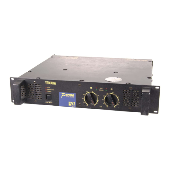
POWER AMPLIFIER Owner's Manual Mode d'emploi Bedienungsanleitung Manual de instrucciónes TEMP PROTECTION POWER CLIP SIGNAL ∞ –dB ∞ EEEngine... - Page 2 • Variable-speed low-noise fan(s) ensures high reliability even under demanding conditions. This owner's manual covers the three models P4500, P3200 and P1600. In order to take full advantage of your power amp and enjoy long and trouble-free operation, please read this owner's manual carefully before use.
-
Page 3: Table Of Contents
4. Do not open the case or attempt repairs or modifica- tions yourself. This product contains no user-serviceable parts. Refer all maintenance to qualified Yamaha service personnel. Opening the case and/or tampering with the internal circuitry will void the warranty. -
Page 4: Controls And Functions
Controls and Functions Front Panel TEMP PROTECTION POWER 1 POWER switch and indicator This is the main POWER switch. Press to power ON the amplifier. Press again to power OFF. The POWER indicator lights up when the amplifier is powered ON. 2 TEMP indicator When the temperature of the heat sink exceeds 85 degrees Celsius, this indicator will light red. -
Page 5: Rear Panel
Rear Panel 1 INPUT terminals (CHANNEL A, B) Three types of balanced terminals for channels A and B are provided. Channel A input terminal is used in Bridge and Parallel mode. • XLR-3-31 type connector They are wired pin 1–ground, pin 2–hot (+), and pin 3 cold (-). -
Page 6: Modes: Stereo/Parallel/Bridge
Modes: STEREO/PARALLEL/BRIDGE STEREO mode In this mode, channels A and B operate independently (as a conventional stereo amp). The CHANNEL A input signal will be output from the CHANNEL A output jacks, and the CHANNEL B input signal will be output from the CHANNEL B output jacks. -
Page 7: Caution For Speaker Connection
P4500; 340 W+340 W (8 ) in stereo and 880 W (8 ) in monaural on the P3200; 160 W+160 W (8 ) in stereo and 400 W (8 ) in monaural on the P1600. Be sure to use a speaker system that has sufficient input capacity. -
Page 8: Rack Mounting
If multiple high-power amp units are mounted in a rack with poor ventilation, the heat from the amps will cause the interior of the amp to become very hot, causing the performance of the amps to be impaired. When mounting amps in a rack, you must make provision for ventilation so that the heat can escape. -
Page 9: Portable Rack Mounting
Portable Rack Mounting The amplifier intakes cool air through the front panel and exhausts warm air out the rear panel. When mounting amplifiers in a portable rack, make sure the rear panel is completely open for ventilation. (Side View) Front Air intake Positioning the Housed Amplifier Place the case so that the ventilation airflow paths are not blocked. -
Page 10: Specifications
500 W/650 VA 103.5 455 mm 16 kg Security cover Ventilation panel: VP1 P3200 P1600 340 W + 340 W 160 W + 160 W 440 W + 440 W 200 W + 200 W 880 W 400 W 370 W + 370 W... -
Page 11: Block Diagram
Block Diagram CHANNEL A (BRIDGE) (PARALLEL) INPUT CHANNEL B Dimensions Ach Power Amp PC Limiter Temperature Sensor (Heat Sink) PARALLEL Bch Power Amp BRIDGE STEREO PC Limiter W:480 SIGNAL CLIP PROTECTION Protection Circuit TEMP CLIP SIGNAL Unit: mm CHANNEL A... -
Page 12: Performance Graphs
Check the amplifier ventila- tion conditions and take appropriate measures to improve airflow around the amplifier. Consult your dealer or nearest Yamaha service center. P3200 Output Power [W] Remedy Protection Circuit The PC limiter circuit operates to protect the power transistors. - Page 13 Ce manuel couvre les modèles P4500, P3200 et P1600. Veuillez le lire complètement pour éviter toute erreur de manipulation et pouvoir jouir de votre amplificateur durant de longues années.
-
Page 14: Commandes Et Fonctions
Commandes et fonctions Panneau avant TEMP PROTECTION POWER 1 Touche et témoin POWER Il s’agit de la touche de mise sous tension. Enfoncez-la pour mettre l’amplificateur sous tension et appuyez une fois de plus sur cette touche pour le mettre hors tension. Le témoin POWER s’allume lorsque l’amplificateur est mis sous tension. -
Page 15: Panneau Arrière
Panneau arrière 1 Bornes d’entrée (INPUT: CHANNEL A, B) Vous avez le choix entre trois types de bornes pour les canaux A et B. Utilisez la borne d’entrée du canal A en mode Bridge et Parallel (pont). • Borne de type XLR-3-31 La masse est à... -
Page 16: Modes: Stereo/Parallel/Bridge
Modes: STEREO/PARALLEL/BRIDGE Mode STEREO Avec ce mode, les canaux A et B sont indépendants (comme sur n’importe quel amplificateur stéréo tradi- tionnel). Le signal du canal A sera émis via les bornes de sortie du canal A tandis que le signal du canal B sera émis via les bornes de sortie du canal B. -
Page 17: Connexion Des Enceintes
340 W+340 W (8 ) en stéréo et 880 W (8 ) en mono sur le P3200; 160 W+160 W (8 ) en stéréo et 400 W (8 ) en mono sur le P1600. Assurez-vous que la puis- sance d’entrée de vos enceintes est adéquate. -
Page 18: Montage En Rack
Pour obtenir une ventilation optimale du rack, placez également une grille de ventilation en haut du rack. Grille de ventilation Yamaha propose une grille de ventilation de 1U (VP1, disponible en option). Montage de quatre amplificateurs maximum avec face arrière... -
Page 19: Montage En "Flightcase
Montage en “flightcase” L’amplificateur de puissance aspire l’air froid par le panneau avant et dégage l’air chaud par le panneau arrière. Utilisez toujours des racks avec une face arrière amovible. (Face latérale) Face avant Arrivée d’air Installation de l’amplificateur à tout autre endroit Disposez toujours votre amplificateur de manière à... -
Page 20: Fiche Technique
500 W/650 VA 103,5 455 mm 16 kg Cache de protection Grille de ventilation: VP1 P3200 P1600 340 W + 340 W 160 W + 160 W 440 W + 440 W 200 W + 200 W 880 W 400 W... -
Page 21: Schéma
Schéma CHANNEL A (BRIDGE) (PARALLEL) INPUT CHANNEL B Dimensions Ach Power Amp PC Limiter CLIP Temperature Sensor (Heat Sink) CLIP Bch Power Amp PARALLEL BRIDGE STEREO PC Limiter L:480 SIGNAL CHANNEL A PROTECTION Protection SPEAKERS Circuit TEMP SIGNAL CHANNEL B... -
Page 22: Graphiques De Performance
Vérifier les conditions d’aéra- tion de l’amplificateur et prendre les mesures néces- saire pour améliorer la circulation autour de l’amplifi- cateur. Consulter votre distributeur ou centre de service Yamaha le plus proche. P3200 Output Power [W] Fonctionnement du Remède circuit de protection Le circuit de limiteur PC fonctionne pour protéger les... - Page 23 Beanspruchung eine optimale Funktion. Diese Bedienungsanleitung bezieht sich auf die Modelle P4500, P3200 und P1600. Bitte lesen Sie sie sich vollständig durch, um bei der Bedienung alles richtig zu machen und über Jahre hinaus einen verläßlichen Betrieb zu gewährleisten.
-
Page 24: Bedienelemente Und Funktionen
Bedienelemente und Funktionen Frontplatte TEMP PROTECTION POWER 1 POWER-Taste und -Diode Dies ist der Netzschalter. Drücken Sie ihn einmal, um die Endstufe einzuschalten und noch einmal, um sie wieder auszuschalten. Die POWER-Diode leuchtet, so- bald Sie den P4500/3200/1600 einschalten. 2 TEMP-Diode Diese Diode leuchtet rot, sobald die Temperatur des Kühlkörpers 85 C oder mehr beträgt. -
Page 25: Rückseite
Rückseite 1 INPUT-Anschlüsse (KANAL A, B) Diese Endstufen sind mit drei symmetrischen Eingangs- typen für Kanal A und B ausgestattet. Im Bridge-Betrieb müssen Sie die Signalquelle an Kanal A anschließen. • XLR-3-31-Buchsen Die Belegung dieser Anschlüsse lautet 1= Masse, 2= heiß... -
Page 26: Betrieb: Stereo/Parallel/Bridge
Betrieb: STEREO/PARALLEL/BRIDGE STEREO-Betrieb In dieser Betriebsart werden Kanal A und B separat angetrieben (genau wie bei einem herkömmlichen Ste- reo-Verstärker). Das an CHANNEL A angelegte Signal liegt dann an den SPEAKERS CHANNEL A-Buchsen an, während das über die CHANNEL B-Eingänge empfangene Signal an SPEAKERS CHANNEL B anliegt. -
Page 27: Achtung Beim Anschließen Der Lautsprecher
(8 ) im Bridge-Betrieb beim P4500; 340 W+340 W (8 ) im Stereo-Betrieb und 880 W (8 ) im Bridge- Betrieb beim P3200; 160 W+160 W (8 ) im Stereo- Betrieb und 400 W (8 ) im Bridge-Betrieb beim P1600. Verwenden Sie also ausschließlich Lautsprecher mit Schraube einer ausreichenden Kapazität. -
Page 28: Rack-Einbau
35% einer 1U-Oberfläche offen sind, um eine ausreichende Luftzirkulation zu gewährleisten. Um eine optimale Belüftung des Racks zu erzielen, sollten Sie auch ganz oben im Rack eine Lüftungsblende verwenden. Lüftungsblende Yamaha bietet eine 1U-Lüftungsblende (VP1, Sonderzubehör) an. Einbau von höchstens vier Endstufen in ein Rack mit offener Rückseite... -
Page 29: Einbau In Ein Bühnen-Rack
Einbau in ein Bühnen-Rack Die Endstufe saugt Kaltluft an der Frontplatte ein und bläst an der Rückseite Warmluft aus. Deshalb sollten Sie nur Racks mit abnehmbarer Front- und Rückplatte verwenden. (Seitenansicht) Frontplatte Luftstrom Festeinbau einer Endstufe Stellen Sie die Endstufe immer so auf, daß eine optimale Luftzirkulation gewährleistet ist. SO NICHT Warmluft Frontseite... -
Page 30: Spezifikationen
500 W/650 VA 103,5 455 mm 16 kg Schutzblende Lüftungsblende: VP1 P3200 P1600 340 W + 340 W 160 W + 160 W 440 W + 440 W 200 W + 200 W 880 W 400 W 370 W + 370 W... -
Page 31: Blockschaltbild
Blockschaltbild CHANNEL A (BRIDGE) (PARALLEL) INPUT CHANNEL B Abmessungen Ach Power Amp PC Limiter Temperature Sensor (Heat Sink) Bch Power Amp PARALLEL BRIDGE STEREO PC Limiter B:480 SIGNAL CLIP PROTECTION Protection Circuit TEMP CLIP SIGNAL Einheit: mm CHANNEL A SPEAKERS... -
Page 32: Leistungsgrafik
Verstärker bekommt nicht genug Luft. Die Belüftung des Verstär- kers prüfen und für ausrei- chende Abführung der entstehenden Wärme sorgen. Händler bzw. Yamaha- Service zu Rat ziehen. P3200 Output Power [W] Abhilfe Schutzschaltung Die Begrenzungsschaltung gegen pulsierenden Strom arbeitet zum Schutz des Leistungstransistors. - Page 33 Este manual de instrucciones cubre tres modelos, P4500, P3200, y P1600. Para sacar el máximo partido de su ampli- ficador de potencia y disfrutar de un funcionamiento dura- dero y sin averías, lea cuidadosamente este manual de instrucciones antes de utilizar el amplificador.
-
Page 34: Controles Y Funciones
Controles y funciones Panel frontal TEMP PROTECTION POWER 1 Interruptor e indicador de alimentación (POWER) Éste es el interruptor de alimentación principal. Presió- nelo para conectar la alimentación del amplificador. Vuelva a presionarlo para desconectarla. Cuando conec- te la alimentación del amplificador, se encenderá el indicador POWER. -
Page 35: Panel Posterior
Panel posterior 1 Terminales de entrada de los canales A y B (INPUT CHANNEL B CHANNEL A) Existen tres tipos de terminales equilibrados para los canales A y B. Los terminales de entrada del canal A se utilizan en el modo en puente. -
Page 36: Modo: Stereo/Parallel/Bridge
Modo: STEREO/PARALLEL/BRIDGE Modo estéreo (STEREO) En este modo, los canales A y B funcionarán indepen- dientemente (como un amplificador estéreo convencio- nal). La señal de entrada de CHANNEL A saldrá a través de las tomas de salida CHANNEL A, y la señal de entrada de CHANNEL B a través de las tomas de salida CHANNEL B. -
Page 37: Precauciones Para La Conexión De Los Altavoces
880 W (8 ) en monoaural en el P3200, y 160 W + 160 W (8 ) en estéreo y 400 W (8 ) en monoaural en el P1600. Cerciórese de utilizar un sistema de altavoces con suficiente capacidad de entrada. -
Page 38: Montaje En Bastidor
La circulación de aire será mejor si la superficie superior del bastidor posee aberturas de ventilación. Panel de ventilación Yamaha proporciona un panel de ventilación VP1 de tamaño IU opcional. Montaje de cuatro amplificadores en un bastidor con la parte posterior abierta Instale el panel de ventilación sobre los amplificadores,... -
Page 39: Montaje En Bastidor Portátil
Montaje en bastidor portátil El amplificador toma aire frío a través del panel frontal y expulsa aire cálido a través del panel posterior. Cuando monte amplificadores en una bastidor portátil, cerciórese de que el panel posterior esté completamente abierto a fin de permitir la ventilación. -
Page 40: Especificaciones
500 W/650 VA 103,5 455 mm 16 kg Cubierta de seguridad Panel de ventilación: VP1 P3200 P1600 340 W + 340 W 160 W + 160 W 440 W + 440 W 200 W + 200 W 880 W 400 W... -
Page 41: Diagramas En Bloques
Diagramas en bloques CHANNEL A (BRIDGE) (PARALLEL) INPUT CHANNEL B Dimensiones Ach Power Amp PC Limiter Temperature Sensor (Heat Sink) Bch Power Amp PARALLEL BRIDGE STEREO PC Limiter An: 480 SIGNAL CLIP PROTECTION Protection Circuit TEMP CLIP SIGNAL Unidad: mm... -
Page 42: Gráficos De Rendimiento
Gráficos de rendimiento P4500 Output Power [W] P1600 Output Power [W] Solución de problemas En la tabla siguiente se indican las causas principales de la operación anormal y las medidas correctivas requeridas, así como la operación del circuito protector en cada caso.