
Related Manuals for Cub Cadet 48-inch Fabricated Deck


Summary of Contents for Cub Cadet 48-inch Fabricated Deck
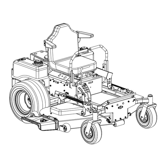
- Page 1 Hydrostatic Zero-Turn Commercial Riding Mower Professional Turf Equipment 48” Fabricated Deck 54” Fabricated Deck 60” Fabricated Deck W/O R.O.P.S. 72” Fabricated Deck OPERATOR’S AND SERVICE MANUAL...
-
Page 2: Table Of Contents
TABLE OF CONTENTS Foreword............. . . 3 General Safety Operations . -
Page 3: Foreword
FORWARD The Tank Hydrostatic Zero-Turn Commercial Riding Mower provides superb maneuverability, mid-mount cutting capability for professional landscapers, commercial lawn service compa- nies, professional turf managers and golf course superintendents. The machine incorporates many safety features that should be studied by all operators and maintenance personnel before use. -
Page 4: General Safety Operations
GENERAL SAFETY OPERATIONS A. DANGER Do not operate machine in confined areas where exhaust gases can accumulate. Do not operate machine without mower chute deflector in place and operational. Do not carry passengers. B. WARNING 1. Do not operate machines under the influence of alcohol or drugs. -
Page 5: Related To Fuel
11. When looking for oil leaks, never run your hand over hydraulic hoses, lines or fittings. Never tighten or adjust hydraulic hoses, lines or fittings while the system is under pressure. If high-pressure oil penetrates the skin, the oil must be removed within a few hours by a doc- tor familiar with this form of injury or serious complications may result. -
Page 6: Safety Decals
SAFETY DECALS AND LABELS WARNING SHIELD MISSING DO NOT OPERATE Part Number: 00030635 Part Number: 01003451 Part Number: 01003452 WARNING Engage parking brake when leaving the machine. Do not add fuel while the engine is hot or running. Stop engine, disconnect spark plug before adjusting or servicing. Before leaving operator's position: Disengage implement drive. -
Page 7: Specifications
SPECIFICATIONS Engine: 19HP Kawasaki, 20 & 24HP Honda, 23 & 25HP Kawasaki, 25 & 27HP Kohler, 28HP Kohler E.F.I., 28 & 33HP Generac Type: Vertical air cooled V-Twin Air Cleaner: Paper Element Lube System: Pressurized with oil filter Starter: 12-volt electric Traction Drive: Engine to two variable-speed hydraulic wheel motors on each drive wheel... -
Page 8: Operating Instructions
OPERATING INSTRUCTIONS Figure. 1 Tach and Electric Blade Hour Meter Clutch Switch Ignition Switch A.General 1. When Mowing: a. Keep adults, children, and pets away from the area to be mowed. b. When operating this mower, in the forward direction, do not allow the steering levers to return to Neutral on their own. -
Page 9: Controls
b. Avoid turning downhill if possible, if not use extra care and go slowly. c. Avoid turning when going downhill, traction is at a minimum going downhill. d. Do not operate with discharge side of the mower toward streets, buildings, play- grounds, parking lots, other machines, ani- mals, and other people. - Page 10 Steering Levers Deck Lift Handle Brake Figure. 3 4. Electric Blade Clutch Switch: (See Figure 1.) Located on the right side of the mower beside the ignition switch. This is an “on/off” push pull switch that controls the electric blade clutch which supplies power to the cut- ting blades through the PTO.
-
Page 11: Initial Adjustments
C.Initial Adjustments 1. Check the fluid levels and tires: Note: These checks should be made daily, before starting the engine. a. Fuel: Using a good grade of unleaded, regular gasoline (for a gasoline engine), fill the fuel tank (beside the engine on the left or right side of the mower). -
Page 12: Zero Turn Break-In And Operating Procedures
clockwise a few turns. Adjust both front and rear Deck links as necessary. Retighten nuts. Raise the mowing deck to the transport position using the transport lever. g. Use the transport lever to lower the mow- ing deck to the cutting position and repeat step “b.”... - Page 13 run. Turn off the PTO by pushing the control switch down. h. To drive in the FORWARD direction: 1. Set the engine speed to 2000 to 2500 rpm (refer to tachometer on right control panel). This must be increased to full speed (3525-3675 rpm) after becoming familiar with the machine.
-
Page 14: Maintenance And Service
e. Push the throttle control to a position a third of the way between slow and fast. Insert the key in the ignition and start switch and turn the switch to “On”. g. Gasoline Engine: If the engine is cold, push the choke to the on position. - Page 15 Figure. 6 d. Detach the mower drive belt. e. Remove six linchpins (See Fig. 6) (4) from the deck and (2) from the front of the mower. Remove the linchpins on the left and right rear side of the cutter deck (2); remove the linchpins on the left and right front side of the cutter deck (2);...
-
Page 16: Hydraulic Oil
Cover Plate Figure. 7 e. Pull the tensioner pulley away from the belt and remove the PTO belt then remove the blade drive belt. Reverse the process to install the belt. Note: When replacing belts do not over- tighten. Adjust the idler pulley so that a ten- pound pull with a spring scale between two pulleys deflects the belt about 1/2". -
Page 17: Specific Gravity
caps and drain oil from both left and right pumps. Replace and retighten nuts. Hydraulic pumps Figure. 9 Unfasten hose and drain from this side of both pumps. Coat new filter seal with oil before installa- tion. Install new hydraulic oil filter filled with new oil. - Page 18 c. Attach the end of the black jumper cable to the Negative terminal of the charged bat- tery. d. Attach the other end of the black jumper cable to the frame of the unit with the low charge battery. Fuses: There is one fuse located in the wiring between the ignition and start switch and other electrical components.
-
Page 19: Tires
parking brake engaged and the blade clutch switch in the “off” position, start the engine. Now release the parking brake, hold down on the back of the operator’s seat against spring pressure, and swing one of the steering levers up to the operat- ing position. -
Page 20: Brakes
opened-out position. If your mower creeps do the following. a. Jack up rear of unit. b. Place Lapbars in neutral opened-out posi- tion. c. Locate jam nuts. (Reference control assembly in parts list). d. Loosen jam nuts on both ends of rod con- nectors. -
Page 21: G.storage
Note: The pumps are not owner-repairable. If a pump fails, contact your Cub Cadet Com- mercial dealer. Do not disassemble the pump. Steering Lever Adjustments: Place the mower on level ground with the engine run- ning, parking brake off and steering levers opened out to the neutral position. -
Page 22: Maintenance Schedule
spray paint. Brush a rust preventive oil on any unpainted surfaces including the pul- leys and blades. (Be careful not to get any oil on the drive belts.) d. Lubricate the mower. e. Drain the engine oil. The engine should be warm so that all the oil drains. -
Page 23: Lubrication Chart
OIL CHART Apply a few drops of SAE 20W-50 engine oil or use a spray lubricant. Apply the oil to both sides of pivot points. Wipe off any excess. Start engine and operate mower briefly to insure that oil spreads evenly. Number of Oil Points Description DAILY... -
Page 24: Performance Adjustments
Performance Adjustments A. High Speed Tracking Adjustment If mower tracks to one side with both lap bars in fully forward position: Check air pressure in all four tires: a. Pressure should be within specified ranges and balanced side-to-side. b. Rear tires 8-10 psi. recommended (20 psi MAX.) c. -
Page 25: Deck Corner Ball Wheel Roller Settings
Repeat as required to obtain proper throt- tle adjustment. g. Verify proper throttle adjustment by check- ing RPM readings as outlined above. C. Deck Corner Ball Wheel Roller Settings Matching the set heights of the ball rollers on the four corners of the mower deck to the desired cut height will prevent edge scalping and minimize any side-to-side variance in cut height. -
Page 26: F Deck Leveling Procedure
F. Deck leveling Procedure Park the mower on a flat paved surface, engage the parking brake, shut off the engine, remove the key from the ignition switch, disconnect the spark plug wires and using the transport lever, lower the mowing deck into the 4" height of cut position. -
Page 27: Wiring Diagram
WIRING DIAGRAM GD: 02000591... - Page 28 Cadet Commercial dealer subject to the above time and coverage limitations. Upon completion of your purchase, the Serial Number/s of the unit will be registered with the Cub Cadet. This will initiate and validate your limited warranty and the applicable Warranty Period.
Need help?
Do you have a question about the 48-inch Fabricated Deck and is the answer not in the manual?
Questions and answers