MIR MiR250 Hook Manual
Hide thumbs
Also See for MiR250 Hook:
- User manual (249 pages) ,
- Installer/integrator manual (170 pages) ,
- Quick start manual (62 pages)
Table of Contents
Advertisement
Quick Links
Advertisement
Table of Contents

Related Manuals for MIR MiR250 Hook


Summary of Contents for MIR MiR250 Hook
- Page 1 MiR250 Hook Integrator Manual Date: 12/2023 Version: 3.0 (en) Robot hardware version: 2.0 Top module hardware version: 2.0 For the full documentation package and for translated guides for your robot, go to: https://www.mobile-industrial-robots.com/product-documents/mir250-hook-hw-20-sw-3-v1/...
-
Page 2: Copyright And Disclaimer
Copyright and disclaimer Copyright and disclaimer Mobile Industrial Robots A/S (MiR) makes no warranties, expressed or implied, in respect of this document or its contents. In addition, the contents of this document are subject to change without prior notice. Every precaution has been taken in the preparation of this document. -
Page 3: Table Of Contents
4.3 Connecting the battery 4.4 Powering up the robot 4.5 Shutting down the robot 4.6 Connecting to the robot interface 4.7 Connecting the robot to a Wi-Fi network MiR250 Hook Integrator Manual (en) 12/2023 - v.3.0 ©Copyright 2021–2023: Mobile Industrial Robots A/S. - Page 4 8.4 Field switching and Personnel detection 8.5 MiR Hook 250 safety functions 9. Demounting the top module 10. Electrical interfaces 10.1 Left side interfaces 10.2 Right side interfaces MiR250 Hook Integrator Manual (en) 12/2023 - v.3.0 ©Copyright 2021–2023: Mobile Industrial Robots A/S.
- Page 5 13.3 Error codes and solutions 14. Transportation 14.1 Lifting MiR250 Hook 14.2 Packing the robot for transportation 14.3 Transporting the battery 15. Disposal 16. Commissioning overview 17. Glossary MiR250 Hook Integrator Manual (en) 12/2023 - v.3.0 ©Copyright 2021–2023: Mobile Industrial Robots A/S.
-
Page 6: About This Document
Integrator Manuals are available in multiple languages. These guides are intended for PCM (partly completed machinery) robots. Quick starts describe how you start operating MiR robots quickly. It comes in print in the box with the robots. Quick starts are available in multiple languages. - Page 7 Best practice guides provide helpful information you can use when commissioning or operating your robot. REST API references for MiR robots, MiR Hooks, and MiR Fleet. HTTP requests can be used to control robots, hooks, and MiR Fleet. MiR Network and Wi-Fi guide specifies the performance requirements of your network and how you must configure it for MiR robots and MiR Fleet to operate successfully.
-
Page 8: Version History
1. About this document Resources MiR Log Analytics and MiR Insights are tools you can use to analyze how well your robots or fleet are performing. MiR Log Analytics is a free tool that lets you analyze recorded performance from error logs, and MiR Insights requires a paid license, but runs continuously alongside MiR Fleet to give real-time data on several metrics. - Page 9 Updated for hardware version 2.0 with new hook computer. Affects sections: MiR Hook 250 and Identification label. Added that it is foreseeable misuse to tow carts into elevators. Affects section: Foreseeable misuse. MiR250 Hook Integrator Manual (en) 12/2023 - v.3.0 ©Copyright 2021–2023: Mobile Industrial Robots A/S.
- Page 10 Updated sections: Obstacle detection, Battery disposal, Disposal of robot, Interface specifications, Markers, and External parts. Updated manual to ensure compliance with radio equipment directives. Affects sections: General safety precautions and Foreseeable misuse. MiR250 Hook Integrator Manual (en) 12/2023 - v.3.0 ©Copyright 2021–2023: Mobile Industrial Robots A/S.
- Page 11 Added information about how the robot picks up and places carts. Affect section: How MiR Hook 250 works. General improvements throughout the manual. Date: 2021-06-15 Robot HW: 1.0 Top module HW: 1.0 First edition. MiR250 Hook Integrator Manual (en) 12/2023 - v.3.0 ©Copyright 2021–2023: Mobile Industrial Robots A/S.
-
Page 12: Product Presentation
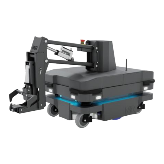
2. Product presentation 2. Product presentation MiR250 Hook is a MiR250 Dynamic robot with a MiR Hook 250 top module mounted to it. It is designed to transport carts indoors within production facilities, warehouses, and other industrial locations where access to the public is restricted. -
Page 13: External Parts
2. Product presentation 2.1 External parts Figure 2.1 MiR250 Hook external parts MiR250 Hook Integrator Manual (en) 12/2023 - v.3.0 ©Copyright 2021–2023: Mobile Industrial Robots A/S. - Page 14 Emergency stop button Hook reset button Hook center cover Antenna: two pcs Nameplate Control panel MiR250 Hook has a control panel in the rear-left corner of the robot. MiR250 Hook Integrator Manual (en) 12/2023 - v.3.0 ©Copyright 2021–2023: Mobile Industrial Robots A/S.
- Page 15 Lets the robot continue operating after the Manual stop button was pressed or after the operating mode changes. Lets the robot start operating after powering up. MiR250 Hook Integrator Manual (en) 12/2023 - v.3.0 ©Copyright 2021–2023: Mobile Industrial Robots A/S.
- Page 16 Manual brake release switch The Manual brake release switch is located below the control panel and releases the mechanical brakes on MiR250 Hook. You release the robot's mechanical brakes by turning the Manual brake release switch clockwise. MiR250 Hook Integrator Manual (en) 12/2023 - v.3.0 ©Copyright 2021–2023: Mobile Industrial Robots A/S.
- Page 17 Once you engage the automatic brake system, the connection to the CAN bus nodes is re- established, and the robot can update its location on the map automatically. The robot cannot operate while the mechanical brakes are released manually. MiR250 Hook Integrator Manual (en) 12/2023 - v.3.0 ©Copyright 2021–2023: Mobile Industrial Robots A/S.
-
Page 18: Internal Parts
2. Product presentation 2.2 Internal parts Most internal parts of MiR250 Hook are accessed through covers that open to different compartments—see "Accessing the internal parts" on page 149. CAUTION Removing covers from the robot exposes parts connected to the power supply, which can result in a short circuit that will damage the robot and could injure personnel. - Page 19 Rear compartment Figure 2.5 Internal parts of the rear compartment Table 2.4 Identification of internal parts in Figure 2.5 Pos. Description Pos. Description Battery Battery connector MiR250 Hook Integrator Manual (en) 12/2023 - v.3.0 ©Copyright 2021–2023: Mobile Industrial Robots A/S.
- Page 20 The unique nameplate of your robot is on the right side compartment cover. Make sure you do not swap the cover with covers from other robots. Figure 2.6 Internal parts of the left side compartment MiR250 Hook Integrator Manual (en) 12/2023 - v.3.0 ©Copyright 2021–2023: Mobile Industrial Robots A/S.
- Page 21 Pos. Description Switch Safe Stop 1 (SS1) contactor Bogie and drivetrain Top compartments The top compartments are only accessible after the top module has been removed. MiR250 Hook Integrator Manual (en) 12/2023 - v.3.0 ©Copyright 2021–2023: Mobile Industrial Robots A/S.
- Page 22 General purpose outputs General purpose inputs Auxiliary safety functions I/Os A Auxiliary safety functions I/Os B MiR Hook 250 The components of MiR Hook 250 are listed in Table 2.8. MiR250 Hook Integrator Manual (en) 12/2023 - v.3.0 ©Copyright 2021–2023: Mobile Industrial Robots A/S.
- Page 23 Auxiliary power connector interface Emergency stop interface Counterweight: three pcs Hook computer GPIO connector Encoder (angular), placed beneath plate Hook reset button Power supply Relay Identification label MiR250 Hook Integrator Manual (en) 12/2023 - v.3.0 ©Copyright 2021–2023: Mobile Industrial Robots A/S.
-
Page 24: How Mir Hook 250 Top Module Works
With MiR250 Hook, you must provide the measurements of the carts as described in "Cart specifications" on page 94. The MiR250 Hook has its own menu in the robot interface. To see the menu options for MiR250 Hook, the hook feature must be enabled—see "Enable the MiR250 Hook feature" on page 68. - Page 25 The robot reads the ID tag, reverses toward the cart, and locks onto the gripper bar. If misaligned more than 5°, the robot may fail to pick up the cart and will abort the action. MiR250 Hook Integrator Manual (en) 12/2023 - v.3.0 ©Copyright 2021–2023: Mobile Industrial Robots A/S.
- Page 26 2. Product presentation Driving with a cart Once a cart is attached to MiR250 Hook, the robot does not reverse when driving to another position. As a result, its dynamic obstacle avoidance capabilities are somewhat restricted compared to when a cart is not attached. The system operator needs to keep this in mind when choosing where to run the robot.
- Page 27 If the Cart position is placed so the back is against a structure or other obstacle, the robot must place the cart in reverse. You can select this in the Place cart action. MiR250 Hook Integrator Manual (en) 12/2023 - v.3.0 ©Copyright 2021–2023: Mobile Industrial Robots A/S.
- Page 28 The left Entry position, which is 1.10 m in front of and 0.20 m to the left of the Cart position. The Entry position from the right The Entry position from the left MiR250 Hook Integrator Manual (en) 12/2023 - v.3.0 ©Copyright 2021–2023: Mobile Industrial Robots A/S.
- Page 29 2. Product presentation The robot checks if the placement space is free and moves forward with the cart. The robot pivots approximately 90° towards the Cart position. MiR250 Hook Integrator Manual (en) 12/2023 - v.3.0 ©Copyright 2021–2023: Mobile Industrial Robots A/S.
- Page 30 Standard: The robot docks using a method between the Fast and Compact methods. It is best to test each method to see which works best for each Cart position. The performance depends significantly on the operating environment. MiR250 Hook Integrator Manual (en) 12/2023 - v.3.0 ©Copyright 2021–2023: Mobile Industrial Robots A/S.
-
Page 31: Light Indicators And Speaker
Status lights The LED light bands on all four sides of the robot use colors and light motion patterns to signal the current status of the robot. MiR250 Hook Integrator Manual (en) 12/2023 - v.3.0 ©Copyright 2021–2023: Mobile Industrial Robots A/S. - Page 32 Figure 2.11 Light indicators on MiR250 Hook Table 2.9 Identification of light indicators in Figure 2.11 Pos. Description Pos. Description Signal lights Status lights MiR250 Hook Integrator Manual (en) 12/2023 - v.3.0 ©Copyright 2021–2023: Mobile Industrial Robots A/S.
- Page 33 When the robot's battery reaches a critically low level of power (0-1%), the ends of the status lights flash red. Signal lights Signal lights are used to indicate the robot’s immediate motion plans by signaling forwards- backwards-braking and left-right turns. MiR250 Hook Integrator Manual (en) 12/2023 - v.3.0 ©Copyright 2021–2023: Mobile Industrial Robots A/S.
- Page 34 In Setup > Sounds, you can upload new sounds to the robot or edit the volume and length of the default sounds. Sounds can be used in missions and zones to alert or to attract people's attention. For more information about how to set up sounds, see MiR Commissioning Guide. You can find this guide on MiR Support Portal.
- Page 35 Settings > Features, you can choose which sound the robot makes and the volume of the sound. Figure 2.12 In the Features settings, you can modify the sounds the robot plays when the robot mutes its Protective fields MiR250 Hook Integrator Manual (en) 12/2023 - v.3.0 ©Copyright 2021–2023: Mobile Industrial Robots A/S.
- Page 36 Do not disable the sound in the safety system. This will also cause the robot to not comply with safety standards. MiR250 Hook Integrator Manual (en) 12/2023 - v.3.0 ©Copyright 2021–2023: Mobile Industrial Robots A/S.
-
Page 37: Safety
Read the information in this section before powering up and operating MiR250 Hook. Pay particular attention to the safety instructions and warnings. MiR250 Hook is partly completed machinery, and there are steps you need to take before it can be put into operation. -
Page 38: Safety Message Types
NOTICE Indicates important information, including situations that can result in damage to equipment or property. Tells you where you can find more information about the topic. MiR250 Hook Integrator Manual (en) 12/2023 - v.3.0 ©Copyright 2021–2023: Mobile Industrial Robots A/S. -
Page 39: General Safety Precautions
The robot may drive over the feet of personnel, causing injury. All personnel must be informed of the side Protective fields of the robot and be instructed to wear safety shoes near an operating robot. MiR250 Hook Integrator Manual (en) 12/2023 - v.3.0 ©Copyright 2021–2023: Mobile Industrial Robots A/S. - Page 40 This equipment is not intended for use in residential environments and may not provide adequate protection to radio reception in such environments. Do not use the robot in residential environments. MiR250 Hook Integrator Manual (en) 12/2023 - v.3.0 ©Copyright 2021–2023: Mobile Industrial Robots A/S.
- Page 41 Nearby personnel may be hit by the hook. Never release the hook brakes while the robot is driving without a cart. MiR250 Hook Integrator Manual (en) 12/2023 - v.3.0 ©Copyright 2021–2023: Mobile Industrial Robots A/S.
-
Page 42: Intended Use
For details about the environmental conditions in which MiR250 Hook should operate, see "Specifications" on page 146. MiR250 Hook is intended to be designed, commissioned, and integrated into a robot system by a system manufacturer. MiR250 Hook Integrator Manual (en) 12/2023 - v.3.0 ©Copyright 2021–2023: Mobile Industrial Robots A/S. -
Page 43: Foreseeable Misuse
"Foreseeable misuse" below. 3.5 Foreseeable misuse Any use of MiR250 Hook deviating from the intended use is deemed as misuse. This includes, but is not limited to: Using the robot to transport people Using the robot on inclines outside the robot's specifications... -
Page 44: In Case Of Fire
MiR Support Portal. 3.7 Warning label MiR250 Hook is supplied with a warning label that specifies that it is strictly prohibited to ride on the robot. The label must be placed on the robot or top module so that it is clearly visible. -
Page 45: Residual Risks
Mobile Industrial Robots has identified the following potential hazards that integrators must inform personnel about and take all precautions to avoid when working with MiR250 Hook: You risk being run over, drawn in, trapped, or struck if you stand in the path of the robot or walk towards the robot or its intended path while it is in motion. -
Page 46: Unboxing
4. Unboxing 4. Unboxing This section describes how to unbox MiR250 Hook. To be able to use MiR250 Hook hardware version 2.0, the robot must be running software version 3.3.2 or higher. 4.1 In the box The box contains: The MiR250 Hook robot Two external antennas A SICK safety laser scanner optics cover cleaning cloth... - Page 47 4. Unboxing Cut the protective straps surrounding the box. Remove the lid from the box. MiR250 Hook Integrator Manual (en) 12/2023 - v.3.0 ©Copyright 2021–2023: Mobile Industrial Robots A/S.
- Page 48 4. Unboxing Take the folder with the printed documents out of the box. Remove four of the five walls of the box and the protective foam blocks. MiR250 Hook Integrator Manual (en) 12/2023 - v.3.0 ©Copyright 2021–2023: Mobile Industrial Robots A/S.
-
Page 49: Connecting The Battery
"Operating the robot" on page 86. 4.3 Connecting the battery To connect the battery to the robot, you need to open the rear compartment—see "Accessing the internal parts" on page 149. MiR250 Hook Integrator Manual (en) 12/2023 - v.3.0 ©Copyright 2021–2023: Mobile Industrial Robots A/S. - Page 50 Pull the battery lock pin out while pushing the battery lever up. The battery lock pin will click into place and lock the battery connector once the battery lever has been pushed all the way up. MiR250 Hook Integrator Manual (en) 12/2023 - v.3.0 ©Copyright 2021–2023: Mobile Industrial Robots A/S.
- Page 51 Reattach the rear cover by tilting it slightly so that the bottom points forward while inserting it into the two attachment sockets. Press the two white buttons while attaching the cover to the robot. MiR250 Hook Integrator Manual (en) 12/2023 - v.3.0 ©Copyright 2021–2023: Mobile Industrial Robots A/S.
-
Page 52: Powering Up The Robot
Press the Power button for three seconds to turn on the robot. The status lights waver orange, and the robot starts the software initialization process. MiR250 Hook Integrator Manual (en) 12/2023 - v.3.0 ©Copyright 2021–2023: Mobile Industrial Robots A/S. - Page 53 Press the Resume button to clear the Protective stop. The robot is now ready for operation. If you are not able to power up the robot upon delivery, see MiR 48V Battery Technical Guide to troubleshoot the issue. You can find this guide on MiR Support Portal.
-
Page 54: Shutting Down The Robot
Press the Power button for three seconds. Wait for the robot to finish the shutdown process. The status lights waver orange, and the Power button blinks red. MiR250 Hook Integrator Manual (en) 12/2023 - v.3.0 ©Copyright 2021–2023: Mobile Industrial Robots A/S. -
Page 55: Connecting To The Robot Interface
You can connect to the robot using an Ethernet cable or an access point. If you are located in North America, the EU, or a part of the EAC, you can purchase a MiR Access Point from MiR. Outside these areas, you need to use your own access point that is approved for use in your region. - Page 56 If you are using an access point, connect your device to the access point. The MiR Access Point Wi-Fi has the following format: MiR_3042XXXXX. Use the password shipped with the access point to connect. MiR250 Hook Integrator Manual (en) 12/2023 - v.3.0 ©Copyright 2021–2023: Mobile Industrial Robots A/S.
-
Page 57: Connecting The Robot To A Wi-Fi Network
To comply with the robot's certification, you must use an Ethernet cable to avoid simultaneously active radio transmitters while setting up the connection to the local Wi-Fi network. MiR250 Hook Integrator Manual (en) 12/2023 - v.3.0 ©Copyright 2021–2023: Mobile Industrial Robots A/S. - Page 58 4. Unboxing Go to System > Settings > Wi-Fi, and select Add connection. MiR250 Hook Integrator Manual (en) 12/2023 - v.3.0 ©Copyright 2021–2023: Mobile Industrial Robots A/S.
- Page 59 Select the network you want the robot to be connected to, and fill out the displayed fields—see the guide How to connect a MiR robot to a Wi-Fi network for more information about the Wi-Fi settings. You can find this guide on MiR Support Portal.
-
Page 60: Enabling Dynamic Footprint And Sick Configuration
MiR250 Dynamic is delivered as a standard MiR250 robot and you must apply the following changes to make the robot have the MiR250 Dynamic capabilities: MiR250 Hook Integrator Manual (en) 12/2023 - v.3.0 ©Copyright 2021–2023: Mobile Industrial Robots A/S. - Page 61 5.2 of ISO 3691-4:2020 must be performed to ensure compliance with the applicable standards. MiR expressly disclaims liability for any and all damages or injuries caused as a result of customers' failure to install, operate, and maintain the robot in strict compliance with the Integrator manual, train personnel as needed for the application, apply additional risk reduction as needed for the application, follow and implement the recommendations in these guidelines.
- Page 62 SICK configuration on MiR250, MiR500, MiR600, MiR1000, and MiR1350. You can find this guide on MiR Support Portal. Contact MiR Technical Support for the password to modify the SICK safety system. MiR250 Hook Integrator Manual (en) 12/2023 - v.3.0 ©Copyright 2021–2023: Mobile Industrial Robots A/S.
-
Page 63: Moving The Robot By Hand
If the robot is stuck, push or pull gently on the corner bumpers or the pull handles to move the robot. Do not push or pull the robot sideways. MiR250 Hook Integrator Manual (en) 12/2023 - v.3.0 ©Copyright 2021–2023: Mobile Industrial Robots A/S. - Page 64 Figure 4.2 When pushing the robot, only push on the corner bumpers or top module Figure 4.3 When pulling the robot, use either the front pull handle or the rear pull handle MiR250 Hook Integrator Manual (en) 12/2023 - v.3.0 ©Copyright 2021–2023: Mobile Industrial Robots A/S.
-
Page 65: Checking The Robot
"Storage" on page 76. MiR250 Hook Integrator Manual (en) 12/2023 - v.3.0 ©Copyright 2021–2023: Mobile Industrial Robots A/S. - Page 66 You can see the software version your robot is running in the bottom left corner of the robot interface. MiR250 Hook Integrator Manual (en) 12/2023 - v.3.0 ©Copyright 2021–2023: Mobile Industrial Robots A/S.
- Page 67 Check that all hardware components work as intended under Monitoring > Hardware health. All elements on the page must have the OK status and a green dot on the left. For more information, see "Error handling" on page 173. MiR250 Hook Integrator Manual (en) 12/2023 - v.3.0 ©Copyright 2021–2023: Mobile Industrial Robots A/S.
-
Page 68: Enable The Mir250 Hook Feature
4. Unboxing 4.11 Enable the MiR250 Hook feature To access the MiR250 Hook settings and mission menus, the MiR250 Hook features must be enabled. To check that they are enabled, follow these steps: Sign in to the robot interface, and go to System > Settings > Features. -
Page 69: Testing The Top Module
Enable the Hook feature. 4.12 Testing the top module To test that the top module of MiR250 Hook is configured and connected correctly, follow the steps in the following sections. MiR250 Hook Integrator Manual (en) 12/2023 - v.3.0 ©Copyright 2021–2023: Mobile Industrial Robots A/S. - Page 70 On the robot, turn the Operating mode key to Manual mode (turn it to the right). In the robot interface, go to Hook > Manual control. MiR250 Hook Integrator Manual (en) 12/2023 - v.3.0 ©Copyright 2021–2023: Mobile Industrial Robots A/S.
- Page 71 Select Manual control. The Resume button on the robot starts blinking. On the robot, press the Resume button. The status lights turn blue, indicating that the robot is in Manual mode. MiR250 Hook Integrator Manual (en) 12/2023 - v.3.0 ©Copyright 2021–2023: Mobile Industrial Robots A/S.
- Page 72 4. Unboxing The Manual control hook options are now available in the dialog box. MiR250 Hook Integrator Manual (en) 12/2023 - v.3.0 ©Copyright 2021–2023: Mobile Industrial Robots A/S.
- Page 73 Do not drive the robot in manual mode with the brake activated if the robot is transporting a cart as this may damage the motors or the brake. MiR250 Hook Integrator Manual (en) 12/2023 - v.3.0 ©Copyright 2021–2023: Mobile Industrial Robots A/S.
- Page 74 In the robot interface, go to Hook > Manual control. In the dialog box, select Home the hook, and wait until the hook stops moving. Under Brake status, select Deactivate. MiR250 Hook Integrator Manual (en) 12/2023 - v.3.0 ©Copyright 2021–2023: Mobile Industrial Robots A/S.
- Page 75 4. Unboxing Manually push the arm close to 0°. Under Brake status, select Activate. Homing is now complete. MiR250 Hook Integrator Manual (en) 12/2023 - v.3.0 ©Copyright 2021–2023: Mobile Industrial Robots A/S.
-
Page 76: Storage
The storage time of the robot and battery depends on the battery's state of charge, the storage conditions, and the battery version. For more information about storage time, see MiR 48V Battery Technical Guide. You can find this guide on MiR Support Portal. - Page 77 To properly troubleshoot any battery issues and for information about the exact time periods and battery voltages that trigger the transitions between states, see MiR 48V Battery Technical Guide. You can find this guide on MiR Support Portal. MiR250 Hook Integrator Manual (en) 12/2023 - v.3.0 ©Copyright 2021–2023: Mobile Industrial Robots A/S.
-
Page 78: Battery And Charging
BMS. The battery is also fused to protect against severe overcurrent events. See MiR 24V Battery Troubleshooting and Technical Guide for more information. You can find this guide on MiR Support Portal. - Page 79 Never smoke or allow an open spark or flame in the vicinity of the robot's battery. Do not use the battery for anything other than MiR250 Hook. MiR250 Hook Integrator Manual (en) 12/2023 - v.3.0 ©Copyright 2021–2023: Mobile Industrial Robots A/S.
-
Page 80: Enabling Fast Swap
Disconnect the battery—see "Disconnecting the battery" on page 82. Unscrew the two small screws mounting the status light bracket to the battery plate. Use a T20 bit. MiR250 Hook Integrator Manual (en) 12/2023 - v.3.0 ©Copyright 2021–2023: Mobile Industrial Robots A/S. - Page 81 Unscrew the two bolts and washers keeping the fast-swap levers raised. Use a 10 mm hex bit for the bolts and a 10 mm hex wrench to keep the nuts in place. MiR250 Hook Integrator Manual (en) 12/2023 - v.3.0 ©Copyright 2021–2023: Mobile Industrial Robots A/S.
-
Page 82: Disconnecting The Battery
Prior to disconnecting the battery, shut down the robot as described under "Shutting down the robot" on page 54. Ensure that the robot is not connected to any charging device. MiR250 Hook Integrator Manual (en) 12/2023 - v.3.0 ©Copyright 2021–2023: Mobile Industrial Robots A/S. - Page 83 If you have enabled fast swap—"Enabling fast swap " on page 80—you can remove the battery by pulling the battery handle. MiR250 Hook Integrator Manual (en) 12/2023 - v.3.0 ©Copyright 2021–2023: Mobile Industrial Robots A/S.
-
Page 84: Usage
The following sections describe how the robot is operated and customized. 7.1 Work environment requirements It is the responsibility of the commissioner to ensure that the environment is suitable for MiR robots. You can find the environment and space requirements under the specifications for... - Page 85 If you intend for the robot to use elevators to travel between floors, verify that the combined weight of the robot, including load, battery, and top module does not exceed the limits of the elevator. MiR250 Hook Integrator Manual (en) 12/2023 - v.3.0 ©Copyright 2021–2023: Mobile Industrial Robots A/S.
-
Page 86: Operating The Robot
7. Usage Evacuation plan In MiR Fleet, it is possible to set up evacuation of robots from one or more zones in case of an emergency situation. Evacuation zones should be created and Evacuation positions should be added to the map—see the guide How to set up evacuation zones and fire alarms in MiR Fleet for more information. - Page 87 Resume button on the robot starts blinking. On the robot, press the Resume button. The status lights turn blue, indicating that the Hook is in Manual mode. MiR250 Hook Integrator Manual (en) 12/2023 - v.3.0 ©Copyright 2021–2023: Mobile Industrial Robots A/S.
- Page 88 Go to Hook > Manual control and select Deactivate. Manually move the hook arm to approximately 0°. Go to Hook > Manual control and under Brake status select Activate. MiR250 Hook Integrator Manual (en) 12/2023 - v.3.0 ©Copyright 2021–2023: Mobile Industrial Robots A/S.
- Page 89 On the robot, press the Resume button. The status lights turn blue, indicating that the robot is in Manual mode. MiR250 Hook Integrator Manual (en) 12/2023 - v.3.0 ©Copyright 2021–2023: Mobile Industrial Robots A/S.
- Page 90 To send the robot to a selected location, open the active map, either in a dashboard or the map editor, and select Send robot to target followed by the location and orientation you want the robot to drive to. MiR250 Hook Integrator Manual (en) 12/2023 - v.3.0 ©Copyright 2021–2023: Mobile Industrial Robots A/S.
-
Page 91: Types Of Stop
Protective stop, internal safety contactors are switched so the robot's top module and all moving parts of the robot do not receive power. You can hear the safety contactors emit audible clicks when they are switched. MiR250 Hook Integrator Manual (en) 12/2023 - v.3.0 ©Copyright 2021–2023: Mobile Industrial Robots A/S. - Page 92 Resume button begins flashing blue after you have released the Emergency stop button. If the robot is in Emergency stop, it will immediately resume an operating state after you press the flashing Resume button. MiR250 Hook Integrator Manual (en) 12/2023 - v.3.0 ©Copyright 2021–2023: Mobile Industrial Robots A/S.
- Page 93 Manual stop brings the robot into the same state as a Protective stop where it can only be brought to an operational state by pressing the Resume button. MiR250 Hook Integrator Manual (en) 12/2023 - v.3.0 ©Copyright 2021–2023: Mobile Industrial Robots A/S.
-
Page 94: Cart Specifications
Figure 7.2 The Manual stop button is the left-most button on the control panel 7.4 Cart specifications This section describes the requirements for the carts that MiR250 Hook are going to tow. Figure 7.3 illustrates the dimensions that must be within a certain range. You must create and design your own cart type or purchase suitable carts that meet the design requirements. - Page 95 "ID tags" on page 97. To enable the robot to pick up a cart, you must define the cart in the interface—see "Creating a cart " on page 104. MiR250 Hook Integrator Manual (en) 12/2023 - v.3.0 ©Copyright 2021–2023: Mobile Industrial Robots A/S.
- Page 96 The total payload should be determined during commissioning. CAUTION Determine the safe total payload for your cart application during commissioning. Ensure that loads are correctly distributed and fastened to the MiR250 Hook. MiR250 Hook Integrator Manual (en) 12/2023 - v.3.0 ©Copyright 2021–2023: Mobile Industrial Robots A/S.
-
Page 97: Id Tags
It is required that at least 25 mm of empty white space surrounds the AprilTag. The tag size is a global parameter so all tags used by MiR250 Hook must have the same sizes if they are in the same site. - Page 98 7. Usage To activate AprilTags, follow these steps: In the robot interface, go to Hook > Settings, and select Advanced Hook. MiR250 Hook Integrator Manual (en) 12/2023 - v.3.0 ©Copyright 2021–2023: Mobile Industrial Robots A/S.
- Page 99 “-”: Remember the hyphen - which separates size and unit from the name. Name: A unique name displayed in the system. Figure 7.5 This QR code reads 75mm-Cart_A MiR250 Hook Integrator Manual (en) 12/2023 - v.3.0 ©Copyright 2021–2023: Mobile Industrial Robots A/S.
-
Page 100: Calibrate Cart
Hook > Manual control, enter values into the Height from floor field to define Entry and Lock heights for the hook to use when docking to and gripping a cart. MiR250 Hook Integrator Manual (en) 12/2023 - v.3.0 ©Copyright 2021–2023: Mobile Industrial Robots A/S. - Page 101 Insert a height which enables the hook gripper to go underneath the cart. This is known as the Entry height. Remember the value as you will need it when defining the dimensions of the cart. MiR250 Hook Integrator Manual (en) 12/2023 - v.3.0 ©Copyright 2021–2023: Mobile Industrial Robots A/S.
- Page 102 Change the height back to the Entry height, and make sure the cart is still positioned over MiR250 Hook. MiR250 Hook Integrator Manual (en) 12/2023 - v.3.0 ©Copyright 2021–2023: Mobile Industrial Robots A/S.
- Page 103 N/A. The calibration is now completed. Do not move the robot, hook, or cart and continue to "Creating a cart " on the next page. MiR250 Hook Integrator Manual (en) 12/2023 - v.3.0 ©Copyright 2021–2023: Mobile Industrial Robots A/S.
-
Page 104: Creating A Cart
To make the robot interface display hook options, you must enable the feature as described in "Enable the MiR250 Hook feature" on page 68. To create a new cart, follow these steps: Go to Hook > Carts, and select Create. MiR250 Hook Integrator Manual (en) 12/2023 - v.3.0 ©Copyright 2021–2023: Mobile Industrial Robots A/S. - Page 105 7. Usage Under Name, write the name corresponding to the ID of the cart. MiR250 Hook Integrator Manual (en) 12/2023 - v.3.0 ©Copyright 2021–2023: Mobile Industrial Robots A/S.
- Page 106 Figure 7.6. Locked wheels offset: The locked wheels offset is the distance from the gripping point of the cart to the locked wheels axis—see Figure 7.6. MiR250 Hook Integrator Manual (en) 12/2023 - v.3.0 ©Copyright 2021–2023: Mobile Industrial Robots A/S.
- Page 107 For more information, see "Cart specifications" on page 94. MiR250 Hook Integrator Manual (en) 12/2023 - v.3.0 ©Copyright 2021–2023: Mobile Industrial Robots A/S.
- Page 108 Name: Is used to identify the calibration settings. This will automatically be filled when you select Detect and MiR250 Hook is correctly positioned to read the ID tag of the cart. Depth and Side Offset: These are used to define the exact position of MiR250 Hook relative to the cart.
- Page 109 Entry height: Defines the height of the hook when the robot can move the gripper beneath the gripper bar. This is the height the robot should currently be set to. Select Detect, and if MiR250 Hook is correctly positioned to read the ID tag of the cart, the Entry height will be entered.
-
Page 110: Safety-Related Functions
Hardware health) and indicates if the robot is in Emergency or Protective stop with the status lights. Figure 8.1 Overview of components involved in each safety function and interface MiR250 Hook Integrator Manual (en) 12/2023 - v.3.0 ©Copyright 2021–2023: Mobile Industrial Robots A/S. -
Page 111: Safety Functions Overview
Checksum: E9B1C0B6 8.2 Emergency stop buttons There is one Emergency stop button on MiR250 Hook. When the button is pressed, it breaks the Emergency stop circuit triggering an Emergency stop. The Emergency stop circuit runs through the Emergency stop button and connects to the safety PLC through the Auxiliary emergency stop interface. -
Page 112: Overspeed Avoidance
The Field switching and Personnel detection safety functions are dependent on each other. The functions make the robot enter Protective stop when the laser scanners detect a person within a MiR250 Hook Integrator Manual (en) 12/2023 - v.3.0 ©Copyright 2021–2023: Mobile Industrial Robots A/S. - Page 113 Scanners measure distances to diffuse reflections, which means that a tolerance is added to the Protective fields to secure a safe detection of persons crossing the Protective fields. The tolerance distance is 65 mm. MiR250 Hook Integrator Manual (en) 12/2023 - v.3.0 ©Copyright 2021–2023: Mobile Industrial Robots A/S.
- Page 114 1.30 to 1.70 m/s 0–2 100 mm 1.70 to 2.10 m/s 0–2 850 mm Forward at max. speed Figure 8.3 The Protective field contours when the robot drives forward MiR250 Hook Integrator Manual (en) 12/2023 - v.3.0 ©Copyright 2021–2023: Mobile Industrial Robots A/S.
- Page 115 -0.50 to -0.90 m/s 0–780 mm -0.90 to -1.00 m/s 0–1 350 mm Backward at max. speed Figure 8.4 The Protective field contours when the robot drives backward MiR250 Hook Integrator Manual (en) 12/2023 - v.3.0 ©Copyright 2021–2023: Mobile Industrial Robots A/S.
- Page 116 Protective fields to the sides The Protective fields on each side of MiR250 Hook vary with the speed of the robot. At speeds below 0.5 m/s, the fields are very small, making it possible for the robot to traverse narrower corridors.
- Page 117 User-configured muting of the Protective fields There are two ways you can mute the Protective fields using the robot interface. You can add the Mute protective fields action to a mission: MiR250 Hook Integrator Manual (en) 12/2023 - v.3.0 ©Copyright 2021–2023: Mobile Industrial Robots A/S.
- Page 118 Add the action Mute protective fields from the Safety system menu. Edit the action parameters so the Protective fields are muted. MiR250 Hook cannot mute specific Protective fields; you can either mute all or none of the fields. Otherwise, the robot reports an error.
- Page 119 8. Safety-related functions Add and drag all the actions you want the robot to execute with muted Protective fields inside the Mute Protective fields action. MiR250 Hook Integrator Manual (en) 12/2023 - v.3.0 ©Copyright 2021–2023: Mobile Industrial Robots A/S.
- Page 120 The Protective fields are automatically muted when the robot docks to most types of markers, including shelves. This ensures that the robot can drive closely to the marker without entering Protective stop. MiR250 Hook Integrator Manual (en) 12/2023 - v.3.0 ©Copyright 2021–2023: Mobile Industrial Robots A/S.
-
Page 121: Mir Hook 250 Safety Functions
Ethernet connection, and the robot enters Protective stop if the error indicates that the hook cannot be controlled reliably. MiR250 Hook Integrator Manual (en) 12/2023 - v.3.0 ©Copyright 2021–2023: Mobile Industrial Robots A/S. -
Page 122: Demounting The Top Module
9. Demounting the top module 9. Demounting the top module If you need to access the robot from the top, you must demount MiR Hook 250. This can be required when troubleshooting issues or replacing robot components. CAUTION Removing covers from the robot exposes parts connected to the power supply, which can result in a short circuit that will damage the robot and could injure personnel. - Page 123 Remove the four M8×100 screws that mount the hook to the robot. Use a 6 mm hex bit. When re-mounting the top module, tighten the bolts to 18 Nm. MiR250 Hook Integrator Manual (en) 12/2023 - v.3.0 ©Copyright 2021–2023: Mobile Industrial Robots A/S.
- Page 124 Screw in four lifting eye bolts in the holes in each corner of the base of the hook. Mount a lifting device on the four lifting eye bolts. MiR250 Hook Integrator Manual (en) 12/2023 - v.3.0 ©Copyright 2021–2023: Mobile Industrial Robots A/S.
- Page 125 Place support blocks between the robot and hook top module. Unplug the GPIO, Emergency stop, Power, and Ethernet cables from the robot's electrical interfaces. MiR250 Hook Integrator Manual (en) 12/2023 - v.3.0 ©Copyright 2021–2023: Mobile Industrial Robots A/S.
- Page 126 After completing the maintenance that required you to remove MiR Hook 250, you can mount the top module again by following the guide How to mount MiR Hook 250 to MiR250. You can find this guide on MiR Support Portal.
- Page 127 When mounting the top module to the robot, make sure that no cables are pinched beneath the top module. This may damage the cables and prevent the top module from working correctly. MiR250 Hook Integrator Manual (en) 12/2023 - v.3.0 ©Copyright 2021–2023: Mobile Industrial Robots A/S.
-
Page 128: Electrical Interfaces
Emergency stop For more information on how the Emergency stop interface is used, see "Emergency stop buttons" on page 111. MiR250 Hook Integrator Manual (en) 12/2023 - v.3.0 ©Copyright 2021–2023: Mobile Industrial Robots A/S. - Page 129 Type: Output Standard function: Safety output 1. Should be connected through Emergency stop buttons to pin 4. MiR Hook 250 function: Connects to pin 4 through the Emergency stop MiR250 Hook Integrator Manual (en) 12/2023 - v.3.0 ©Copyright 2021–2023: Mobile Industrial Robots A/S.
- Page 130 Standard function: Safety input 2. Should be connected through Emergency stop buttons to pin 3. MiR Hook 250 function: Connects to pin 3 through the Emergency stop buttons. Signal name: Restart Type: Input MiR250 Hook Integrator Manual (en) 12/2023 - v.3.0 ©Copyright 2021–2023: Mobile Industrial Robots A/S.
- Page 131 MiR Hook 250 function: Connects to light in the Reset button on the hook. Not connected to the robot Not connected to the robot Not connected to the robot MiR250 Hook Integrator Manual (en) 12/2023 - v.3.0 ©Copyright 2021–2023: Mobile Industrial Robots A/S.
- Page 132 Connecting 48 V power supplies to 24 V pins or vice versa can lead to severe damage to the robot. Never connect 48 V power supplies to 24 V pins or vice versa. MiR250 Hook Integrator Manual (en) 12/2023 - v.3.0 ©Copyright 2021–2023: Mobile Industrial Robots A/S.
- Page 133 2 A for the first 100 ms, and thereafter under 10 A. MiR Hook 250 function: Unused. Signal name: GND Type: Ground Standard function: Power ground. MiR Hook 250 function: Unused. MiR250 Hook Integrator Manual (en) 12/2023 - v.3.0 ©Copyright 2021–2023: Mobile Industrial Robots A/S.
- Page 134 Standard function: Power ground. MiR Hook 250 function: Connects to power supply. Signal name: Isolated 24V Max. current: 2 A Voltage range: 22.8–25.2 V, with reference to pin 6 Type: Output MiR250 Hook Integrator Manual (en) 12/2023 - v.3.0 ©Copyright 2021–2023: Mobile Industrial Robots A/S.
- Page 135 Standard function: Must be used with pin 5 to be galvanically isolated from the rest of the robot. MiR Hook 250 function: Connects to the motor controllers and hook computer. Unassigned MiR250 Hook Integrator Manual (en) 12/2023 - v.3.0 ©Copyright 2021–2023: Mobile Industrial Robots A/S.
-
Page 136: Right Side Interfaces
10.2 Right side interfaces This section describes the general purpose interfaces that are used to interface to the top module on the right side of the robot. MiR250 Hook Integrator Manual (en) 12/2023 - v.3.0 ©Copyright 2021–2023: Mobile Industrial Robots A/S. - Page 137 Standard function: Output 1. Maximum 1 A at 24 V. MiR Hook 250 function: Turns the hook computer on and off when the robot is turned on and off. Signal name: GND Type: Ground MiR250 Hook Integrator Manual (en) 12/2023 - v.3.0 ©Copyright 2021–2023: Mobile Industrial Robots A/S.
- Page 138 Type: Output Standard function: Output 3. Maximum 1 A at 24 V. MiR Hook 250 function: Unassigned. Signal name: GND Type: Ground Standard function: Protected return. MiR Hook 250 function: Unassigned. MiR250 Hook Integrator Manual (en) 12/2023 - v.3.0 ©Copyright 2021–2023: Mobile Industrial Robots A/S.
- Page 139 Signal name: IN1 Type: Input Standard function: Input 1. MiR Hook 250 function: Unassigned. Signal name: 24V Type: Output Standard function: 24 V output. 2 A maximum. MiR Hook 250 function: Unassigned. MiR250 Hook Integrator Manual (en) 12/2023 - v.3.0 ©Copyright 2021–2023: Mobile Industrial Robots A/S.
- Page 140 MiR Hook 250 function: Unassigned. Signal name: 24V Type: Output Standard function: 24 V output. 2 A maximum. MiR Hook 250 function: Unassigned. Signal name: IN4 Type: Input Standard function: Input 4. MiR250 Hook Integrator Manual (en) 12/2023 - v.3.0 ©Copyright 2021–2023: Mobile Industrial Robots A/S.
- Page 141 The Auxiliary safety functions interfaces are designed to support Emergency and Protective stops and other safety functions. This interface is not used when MiR Hook 250 is mounted to MiR250 Dynamic. MiR250 Hook Integrator Manual (en) 12/2023 - v.3.0 ©Copyright 2021–2023: Mobile Industrial Robots A/S.
- Page 142 Standard function: When inactive, the robot enters Protective stop. If this pin and the other Safeguarded stop pin are unequally set for a period greater than MiR250 Hook Integrator Manual (en) 12/2023 - v.3.0 ©Copyright 2021–2023: Mobile Industrial Robots A/S.
- Page 143 MiR Hook 250 function: Unassigned. Signal name: Shared emergency stop out 1 Type: Output Standard function: Is inactive when the robot is in Emergency stop. MiR Hook 250 function: Unassigned. MiR250 Hook Integrator Manual (en) 12/2023 - v.3.0 ©Copyright 2021–2023: Mobile Industrial Robots A/S.
- Page 144 Signal name: Reduced speed 2 Type: Input Standard function: When inactive, the robot drives with reduced speed. The reduced speed function is not a safety-rated function. MiR Hook 250 function: Unassigned. MiR250 Hook Integrator Manual (en) 12/2023 - v.3.0 ©Copyright 2021–2023: Mobile Industrial Robots A/S.
- Page 145 Standard function: Is active when the robot is standing still. MiR Hook 250 function: Unassigned. Signal name: SAFE_RETURN Standard function: Safe return for output signals. MiR Hook 250 function: Unassigned. MiR250 Hook Integrator Manual (en) 12/2023 - v.3.0 ©Copyright 2021–2023: Mobile Industrial Robots A/S.
-
Page 146: Specifications
0 N, the cart desing may not result in a signifigant downwards or Maximum supporting force of hook upwards force on the hook gripper Battery Battery model MiR 48V Battery Battery type Lithium-ion Battery weight 14 kg Battery dimensions 495×210×75 mm MiR250 Hook Integrator Manual (en) 12/2023 - v.3.0 ©Copyright 2021–2023: Mobile Industrial Robots A/S. - Page 147 We recommend either avoiding these materials, covering them with opaque and matte material the robot can detect, or ensuring the robot does not operate in areas with these materials. MiR250 Hook Integrator Manual (en) 12/2023 - v.3.0 ©Copyright 2021–2023: Mobile Industrial Robots A/S.
-
Page 148: Maintenance
Disconnect the battery—see "Disconnecting the battery" on page 82. If the maintenance can not be performed with battery disconnected ensure that MiR250 Hook is set in Locked mode. MiR250 Hook Integrator Manual (en) 12/2023 - v.3.0 ©Copyright 2021–2023: Mobile Industrial Robots A/S. -
Page 149: Accessing The Internal Parts
12. Maintenance 12.2 Accessing the internal parts Most internal parts of MiR250 Hook are accessed through covers that open to different compartments. See a video of the process on the MiR TechComm videos channel on vimeo.com. CAUTION Removing covers from the robot exposes parts connected to the power supply, which can result in a short circuit that will damage the robot and could injure personnel. - Page 150 Loosen the bottom corners one at the time by pulling out each corner. Loosen the top corners one at the time by pulling each corner down, and then out. MiR250 Hook Integrator Manual (en) 12/2023 - v.3.0 ©Copyright 2021–2023: Mobile Industrial Robots A/S.
- Page 151 Pull off the cover. Rear compartment To open the rear compartment, follow these steps: Push the two white buttons on the rear cover at the same time. MiR250 Hook Integrator Manual (en) 12/2023 - v.3.0 ©Copyright 2021–2023: Mobile Industrial Robots A/S.
- Page 152 Loosen the bottom corners one at the time by pulling out each corner. Loosen the top corners one at the time by pulling each corner down, and then out. MiR250 Hook Integrator Manual (en) 12/2023 - v.3.0 ©Copyright 2021–2023: Mobile Industrial Robots A/S.
- Page 153 To open a side compartment, follow these steps: Remove the front cover and rear cover—see "Front compartment" on page 149 "Rear compartment" on page 151. Turn the two screws counterclockwise. Use a T30 bit. MiR250 Hook Integrator Manual (en) 12/2023 - v.3.0 ©Copyright 2021–2023: Mobile Industrial Robots A/S.
- Page 154 Loosen the bottom corners one at the time by pulling out each corner. Pull off the cover. Top compartments The top compartments are only accessible after the top module has been removed. MiR250 Hook Integrator Manual (en) 12/2023 - v.3.0 ©Copyright 2021–2023: Mobile Industrial Robots A/S.
- Page 155 Unscrew and remove the antenna from the top cover. Unscrew the nut from the antenna connector, and push the antenna cable free of the cover. Use a 10 mm wrench. MiR250 Hook Integrator Manual (en) 12/2023 - v.3.0 ©Copyright 2021–2023: Mobile Industrial Robots A/S.
- Page 156 12. Maintenance Unscrew the four screws. Use a T10 bit. Pull off the cover. MiR250 Hook Integrator Manual (en) 12/2023 - v.3.0 ©Copyright 2021–2023: Mobile Industrial Robots A/S.
- Page 157 12. Maintenance MiR Hook 250 To access the internal parts of MiR Hook 250, follow these steps: Remove the center cover by unscrewing the four screws. Use a T25 bit. MiR250 Hook Integrator Manual (en) 12/2023 - v.3.0 ©Copyright 2021–2023: Mobile Industrial Robots A/S.
- Page 158 Remove the antennas from the front cover. Remove the front and rear covers by lifting them slightly up and out. The covers are held in place with magnets. MiR250 Hook Integrator Manual (en) 12/2023 - v.3.0 ©Copyright 2021–2023: Mobile Industrial Robots A/S.
-
Page 159: Periodic Checks
Remove the internal front and rear covers by unscrewing the eight screws (four in each cover). Use a T25 screwdriver. 12.3 Periodic checks The following maintenance schedules give an overview of regular cleaning and parts replacement procedures. MiR250 Hook Integrator Manual (en) 12/2023 - v.3.0 ©Copyright 2021–2023: Mobile Industrial Robots A/S. - Page 160 Regular weekly checks and maintenance tasks Once a week, carry out the maintenance tasks in Table 12.1. MiR250 Hook Integrator Manual (en) 12/2023 - v.3.0 ©Copyright 2021–2023: Mobile Industrial Robots A/S.
- Page 161 Check if the safety markings around operating hazard zones are the floor intact and visible. Information Check if the safety stickers, identification label, and nameplate on stickers the robot are still intact and visible. MiR250 Hook Integrator Manual (en) 12/2023 - v.3.0 ©Copyright 2021–2023: Mobile Industrial Robots A/S.
- Page 162 How to replace the safety laser Robot reports contamination scanners on MiR250. errors. If only the optics cover is damaged, you can replace the cover alone. See SICK's MiR250 Hook Integrator Manual (en) 12/2023 - v.3.0 ©Copyright 2021–2023: Mobile Industrial Robots A/S.
- Page 163 If you replace the cover with the robot's nameplate, make sure to mount a new copy of the nameplate to the replacement cover. MiR250 Hook Integrator Manual (en) 12/2023 - v.3.0 ©Copyright 2021–2023: Mobile Industrial Robots A/S.
- Page 164 Hook gripper Check for cracks or bending, and Hook gripper becomes unstable. and vertical check the springs. Damage to the gripper increase. console MiR250 Hook Integrator Manual (en) 12/2023 - v.3.0 ©Copyright 2021–2023: Mobile Industrial Robots A/S.
- Page 165 How to replace the MiR Hook100/200 hook brake with the hook brake service kit Hook Check the gripper function and If the home point is not MiR250 Hook Integrator Manual (en) 12/2023 - v.3.0 ©Copyright 2021–2023: Mobile Industrial Robots A/S.
- Page 166 18 Nm. Figure 12.1 The marked hook pins are held in place with locking rings MiR250 Hook Integrator Manual (en) 12/2023 - v.3.0 ©Copyright 2021–2023: Mobile Industrial Robots A/S.
- Page 167 Check every six months Part Maintenance Symptoms of neglect Drive wheels Check wheel surfaces for wear. If Robot cannot travel over large MiR250 Hook Integrator Manual (en) 12/2023 - v.3.0 ©Copyright 2021–2023: Mobile Industrial Robots A/S.
- Page 168 You can also measure the diameter of the wheels to assess how worn down they are, and replace if the diameter is less than 122 mm. Replace all four caster wheels MiR250 Hook Integrator Manual (en) 12/2023 - v.3.0 ©Copyright 2021–2023: Mobile Industrial Robots A/S.
- Page 169 Emergency stop Replace to ensure the reliability Pressing the Emergency stop button(s) of the robot's safety functions. button does not bring the robot into Emergency stop. MiR250 Hook Integrator Manual (en) 12/2023 - v.3.0 ©Copyright 2021–2023: Mobile Industrial Robots A/S.
- Page 170 If you suspect the robot has suffered any damage, you need to conduct a thorough inspection to ensure that the robot's strength and structure is not compromised. MiR250 Hook Integrator Manual (en) 12/2023 - v.3.0 ©Copyright 2021–2023: Mobile Industrial Robots A/S.
-
Page 171: Updating Software
When updating a MiR250 Hook, keep the following points in mind: Never turn off MiR250 Hook during the update process. If your robot has a MiR hook mounted to it, make sure to update the robot software before updating the hook. -
Page 172: Creating Backups
Backups take up some of your robot's memory space. It is a good idea to remove any old backups you are certain you will not need in the future. For more information on how to create, roll back, and delete backups, see MiR Robot Interface Guide. You can find this guide on MiR Support Portal. -
Page 173: Error Handling
Use Try/Catch actions to make the robot react in a specific way if it fails to execute certain actions. Use Prompt user actions in missions that require intervention from users. MiR250 Hook Integrator Manual (en) 12/2023 - v.3.0 ©Copyright 2021–2023: Mobile Industrial Robots A/S. -
Page 174: Hardware Errors
For more information about commissioning your robot to fulfill these guidelines, and for setting up missions and error handling, see MiR Robot Interface Guide and MiR Commissioning Guide. You can find these guides on MiR Support Portal. -
Page 175: Error Codes And Solutions
You can find these guides on MiR Support Portal. 13.3 Error codes and solutions Use the MiR troubleshooting guide to resolve many of the errors the robot reports. You can find these guides on MiR Support Portal. Table 13.1 Common error codes the robot reports... - Page 176 Refer to the solution in error "1003" above. 10101 Mission error. An action in your mission cannot be completed. An exception has been MiR250 Hook Integrator Manual (en) 12/2023 - v.3.0 ©Copyright 2021–2023: Mobile Industrial Robots A/S.
- Page 177 Goal position Requires your active map. '<position_name>' interaction. is in obstacle. Review your active map, and check that dynamic obstacles (objects in the area MiR250 Hook Integrator Manual (en) 12/2023 - v.3.0 ©Copyright 2021–2023: Mobile Industrial Robots A/S.
- Page 178 If you cannot find the issue, open the mission editor and save the mission again, or save a copy of the mission and MiR250 Hook Integrator Manual (en) 12/2023 - v.3.0 ©Copyright 2021–2023: Mobile Industrial Robots A/S.
- Page 179 The robot was not able to follow its global path and has created a new path. The local planner May require failed repeatedly to interaction if you This error may occur occasionally while MiR250 Hook Integrator Manual (en) 12/2023 - v.3.0 ©Copyright 2021–2023: Mobile Industrial Robots A/S.
- Page 180 Technical Support for analysis. For a full list of MiR error codes, see Error codes and solutions on MiR Support Portal. MiR250 Hook Integrator Manual (en) 12/2023 - v.3.0 ©Copyright 2021–2023: Mobile Industrial Robots A/S.
-
Page 181: Transportation
Remove the four M8 mounting bolts in the top plate of the robot. Use a T45 bit. Tighten the bolts to 15 Nm when remounting them. MiR250 Hook Integrator Manual (en) 12/2023 - v.3.0 ©Copyright 2021–2023: Mobile Industrial Robots A/S. - Page 182 The eye bolts should be oriented in parallel to the opposite diagonal bolt to ensure stable lifting. Use an appropriate lifting device to lift the robot. The lifting device should be capable of lifting at least 400 kg. MiR250 Hook Integrator Manual (en) 12/2023 - v.3.0 ©Copyright 2021–2023: Mobile Industrial Robots A/S.
-
Page 183: Packing The Robot For Transportation
Use the original packaging materials when transporting the robot. Figure 14.1 The packing materials The packaging materials are: The bottom of the box (the pallet) The lid of the box (the ramp) MiR250 Hook Integrator Manual (en) 12/2023 - v.3.0 ©Copyright 2021–2023: Mobile Industrial Robots A/S. -
Page 184: Transporting The Battery
Do not expose the battery to direct sunlight. Do not expose the battery to temperatures above 35° C. Do not expose the battery to air humidity above 85%. MiR250 Hook Integrator Manual (en) 12/2023 - v.3.0 ©Copyright 2021–2023: Mobile Industrial Robots A/S. - Page 185 Never smoke or allow an open spark or flame in the vicinity of the robot's battery. Do not use the battery for anything other than MiR250 Hook. MiR250 Hook Integrator Manual (en) 12/2023 - v.3.0 ©Copyright 2021–2023: Mobile Industrial Robots A/S.
-
Page 186: Disposal
A recycling label indicates that the battery needs to be recycled and not disposed as municipal waste—see Figure 15.1. Contact your distributor to get specific information about their take back service. Figure 15.1 Battery disposal symbols MiR250 Hook Integrator Manual (en) 12/2023 - v.3.0 ©Copyright 2021–2023: Mobile Industrial Robots A/S. -
Page 187: Commissioning Overview
Only persons assigned with the commissioning task should be present during commissioning. MiR Commissioning Guide contains a site acceptance checklist with the core tasks that are part of commissioning the MiR robot. - Page 188 16. Commissioning overview Figure 16.1 Flow diagram of the commissioning process MiR250 Hook Integrator Manual (en) 12/2023 - v.3.0 ©Copyright 2021–2023: Mobile Industrial Robots A/S.
-
Page 189: Glossary
Emergency stop. To do this, you must release the Emergency stop button and then press the Resume button. MiR250 Hook Integrator Manual (en) 12/2023 - v.3.0 ©Copyright 2021–2023: Mobile Industrial Robots A/S. - Page 190 MiR250 Hook; and ensuring the safety of nearby personnel when a MiR robot is accelerating, braking, and maneuvering. Typically, an Integrator commissions a system on behalf of a system manufacturer (e.g.
- Page 191 Marker type A marker type is a description of a shelf that MiR robots can dock to. You must have a marker type for each type and size of shelf you want your robot to be able to transport.
- Page 192 17. Glossary MiR application A MiR application is either a single MiR product or a combination of MiR products that is able to execute certain tasks. A MiR application is often a MiR base robot combined with a MiR top module.
- Page 193 REST API REST API is used by MiR Fleet and MiR robots to communicate status data and orders. Site A site is the overall container of any number of maps and all data relevant to the map, such as missions, features, robot groups, and transitions.
- Page 194 17. Glossary MiR250 Hook Integrator Manual (en) 12/2023 - v.3.0 ©Copyright 2021–2023: Mobile Industrial Robots A/S.
- Page 195 17. Glossary Doc. no.: 301035 MiR250 Hook Integrator Manual (en) 12/2023 - v.3.0 ©Copyright 2021–2023: Mobile Industrial Robots A/S.
Need help?
Do you have a question about the MiR250 Hook and is the answer not in the manual?
Questions and answers