ZURN AquaSense ZER-TM Series Installation, Operation, Maintenance And Parts Manual
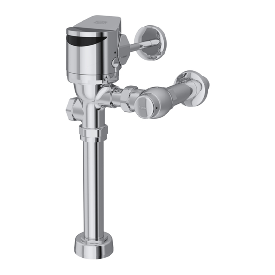
Automatic sensor-operated gear driven type flushometer for water closets and urinals
Hide thumbs
Also See for AquaSense ZER-TM Series:
Table of Contents
Advertisement
Quick Links
Water Closet Battery Models:
ZER6000AV-ONE-TM
ZER6000AV-HET-TM
ZER6000AV-WS1-TM
ZER6000AV-DF-TM
Water Closet Hardwired Models:
ZER6000AV-ONE-TM-HW
ZER6000AV-HET-TM-HW
ZER6000AV-WS1-TM-HW
ZER6000AV-DF-TM-HW
Compliance:
• ADA Compliant
• ASSE 1037/ASME A112.1037/CSA B125.37
• cUPC
WARNING: Cancer and Reproductive Harm - www.P65Warnings.ca.gov
ADVERTENCIA: Cáncer y daño reproductivo - www.P65Warnings.ca.gov
AVERTISSEMENT: Cancer et effets néfastes sur la reproduction - www.P65Warnings.ca.gov
All goods sold hereunder are warranted to be free from defects in material and factory workmanship for a period of three years from the date of purchase.
Decorative finishes warranted for one year. We will replace at no costs goods that prove defective provided we are notified in writing of such defect and the
goods are returned to us prepaid at Sanford, NC, with evidence that they have been properly maintained and used in accordance with instructions. We shall
not be responsible for any labor charges or any loss, injury or damages whatsoever, including incidental or consequential damages. The sole and exclusive
remedy shall be limited to the replacement of the defective goods. Before installation and use, the purchaser shall determine the suitability of the product for his
intended use and the purchaser assumes all risk and liability whatever in connection therewith. Where permitted by law, the implied warranty of merchantability
is expressly excluded. If the products sold hereunder are "consumer products," the implied warranty of merchantability is limited to a period of three years and
shall be limited solely to the replacement of the defective goods. All weights stated in our catalogs and lists are approximate and are not guaranteed.
NOTICE: READ ENTIRE MANUAL PRIOR TO INSTALLING PRODUCT
1.1 gpf
1.28 gpf
1.6 gpf
1.1/1.6 gpf
1.1 gpf
1.28 gpf
1.6 gpf
1.1/1.6 gpf
LIMITED WARRANTY
AquaSense
ZER-TM Series
Automatic Sensor-Operated Gear
Driven Type Flushometer for Water
Closets and Urinals
Installation, Operation, Maintenance
and Parts Manual
Urinal Battery Models:
ZER6003AV-ULF-TM
ZER6003AV-EWS-TM
ZER6003AV-WS1-TM
Urinal Hardwired Models:
ZER6003AV-ULF-TM-HW
ZER6003AV-EWS-TM-HW
ZER6003AV-WS1-TM-HW
• Texas Accessibility Standard (TAS)
• WaterSense Compliant
®
0.125 gpf
0.5 gpf
1.0 gpf
0.125 gpf
0.5 gpf
1.0 gpf
Advertisement
Table of Contents

Related Manuals for ZURN AquaSense ZER-TM Series


Summary of Contents for ZURN AquaSense ZER-TM Series
- Page 1 AquaSense ® ZER-TM Series Automatic Sensor-Operated Gear Driven Type Flushometer for Water Closets and Urinals Installation, Operation, Maintenance and Parts Manual Water Closet Battery Models: Urinal Battery Models: ZER6000AV-ONE-TM 1.1 gpf ZER6003AV-ULF-TM 0.125 gpf ZER6000AV-HET-TM 1.28 gpf ZER6003AV-EWS-TM 0.5 gpf ZER6000AV-WS1-TM 1.6 gpf ZER6003AV-WS1-TM...
-
Page 2: Specifications
Operating Temperature: 35°F to 104°F [2°C to 40°C] Important Safety Information • Do not convert or modify this Zurn product. All warranties will be voided. • All plumbing is to be installed in accordance with applicable codes and regulations. • Water supply lines must be sized to provide an adequate volume of water for each fixture. -
Page 3: Package Contents
Package Contents ZER-TM ZER-TM-HW Sweat solder Vacuum Breaker Vacuum Breaker Control Stop Connection and Spud and Spud with Vandal Cap with Cast Wall Connection for Connection for (Optional with Aqua Flush) Escutcheon Urinal Water Closet Required Tools Optional Accessories 3/32”, 5/64” Strap Wrench Allen Wrench (Supplied) - Page 4 Sweat Solder Adapter Installation Instructions NOTE: Before installation, turn off water supplies to existing fixture and remove flushometer if replacing an existing device. 1. Measure distance from finished wall to the center line of the fixture 2. Slide threaded sweat solder adapter onto water supply pipe until spud. If necessary, cut water supply pipe 1-1/4” shorter than this shoulder stops on end of pipe. Then sweat-solder the adapter to measurement. Deburr by chamfering O.D. and I.D of end of water water supply pipe.
- Page 5 Flush Valve Installation Prior to attaching flush valve tailpiece to control stop, inspect and Control Stop verify that the O-ring seal is located within the O-ring groove at the tailpiece. Ensure that the locking nut and locking snap ring O-Ring Groove are also present on the tailpiece. Snap Ring Lubricate O-ring with water if necessary and insert flush valve tailpiece into the control stop valve.
- Page 6 Battery Installation (For both Battery and Hardwired) 2. As shown, insert 6 (for battery-powered) or 4 (for hardwired) AA 1. Turn battery tray screw counterclockwise with the 3/32” Allen Alkaline batteries (supplied) into the battery tray. Wrench until it loose and comes out. Then, slide the battery tray out by hand; the battery screw will stay in the housing. Battery orientation for battery-powered 3. Slide the battery tray back into the valve head and apply firm pressure.
- Page 7 Alternate Hardwired Installation (For Hardwired Only) Connect Hardwired directly to HW6 Power Converter. (Recommended if one to two flush valves are powered by one HW6.) 1. Using appropriate tools, cut the RED power connector from the 2. Secure the RED wire to the Positive (+) screw terminal and the end of the power supply cable . Then, strip back the wire insulation BLACK wire to the Negative (-) screw terminal on the HW6.
- Page 8 Sensor Angle Adjustment (when necessary) 1.Turn off control stop using a flat head screwdriver turning clockwise. Afterward, utilize the manual override button to flush water out of the flush valve. 2. Before loosening the locking ring, ensure that both the strap wrench and locking ring are completely dry. This will optimize the grip of the strap wrench on the locking ring. Use tape or a marker to mark the original position of the locking ring in relation to the valve body.
- Page 9 Retrofit Installation Instruction 1. Turn off the control stop by turning it clockwise using a flat head screwdriver. Then, use the electronic or manual override button or manual handle to flush the water out of the flush valve. 2. Remove the existing valve cap/head and diaphragm kit from the valve body to achieve the desired state shown on the top right. 3. (FOR ULF UNIVERSAL KIT ONLY) Loosen the tailpiece nut from the control stop and slide the tailpiece out of the control stop. If the valve body does not have matching tailpiece tabs as shown one the right, carefully insert the tailpiece into the control stop, tighten the tailpiece nut, and...
- Page 10 Sensor Range Adjustment (when necessary) To ensure optimal performance in various restroom environments, each ZER-TM is initially calibrated at the factory. However, in situations where there is low light or high reflectivity, it might be necessary to make adjustments to the calibration distance of the unit. This can be done using a Magic Magnet (P6900-AT-MAG). Follow the steps outlined below to re-calibrate the ZER-TM using a Magic Magnet (P6900-AT-MAG): 1. Stand at the desired calibration distance:...
-
Page 11: Care And Cleaning Instruction
Dual Flush User Guide (For ZER6000AV-DF-TM Only) • The Dual Flush model supplies flush volumes of 1.1 and 1.6 gallons per flush. When a user is present for less than 60 seconds, the valve will flush with 1.1 gallons of water. When a user is present for over 60 seconds, the valve consumes 1.6 gallons of water. A user must be present for a minimum of 8 seconds in order to trigger a flush. • The Dual Flush model must be paired with a fixture with a flush volume range that includes 1.1 to 1.6 gallons per flush. For a list of recommended bowls, please refer to our website, www.zurn.com, or speak with your local Zurn rep. Care and Cleaning Instruction • Do not use any abrasive or chemical cleaners to clean the flushometer. • The suggested cleaning of chrome plated surfaces is simply to clean them with mild soap and water, then dry. Commercial cleaning compounds are never recommended. • Upon cleaning other areas of the restroom, be sure the sensor lenses are protected from other cleaning chemicals/solvents to prevent potential damages to the sensor and/or electronics. -
Page 12: Troubleshooting Guide
Trouble Shooting Guide Problem Indicator Cause Corrective Action No water flushed. Stop valve is closed Open stop valve Sensor flashes 5 times in Flush cycle did not complete Contact Customer Service for further quick succession instruction Batteries not making contact No sensor light Remove and reinstall batteries correctly, Critically low battery voltage or replace batteries See Battery installation for reference. - Page 13 Settings for instructions on changing every [24 / 48 / 72] hours after no usage dipswitch settings to achieve desired (default is OFF). trap exchange timing. For further assistance with troubleshooting, visit http://www.zurn.com/ FV838 Rev. A 10/5/2023 Page 11...
- Page 14 ZER-TM Series Repair Kits Part Identification Valve Body 16. Cast Wall Escutcheon 31. Diaphragm Kit Vacuum Breaker Duckbill 17. Setscrew for Cast Wall Flange 32. Volume Control Ring Vacuum Breaker Tube 18. Piston Seal 33. Manifold Stem O-Ring Vacuum Breaker Tube Nut 19.
- Page 15 Service Parts Control Stop Repair Kit and Parts Product No. ZER-TM Valve Head Repair Kit and Parts Product No. Control Stop Repair Kit for 1” and 3⁄4”, Locking Ring, Item 35 PER6000-M-RING P6000-D-SD Items 18-24 Sloan Locking Ring, Item 36 PER6000-M-RING-S © Seal Seat for 1” and 3/4”, Item 18 P6000-D42 Valve Head, (1.1 gpf), Item 34 PERK6000-L-1.1 VP Control Stop Repair Kit for 1” and 3/4”, Valve Head, (1.28 gpf), Item 34 PERK6000-L-1.28 P6000-D-VP Items 18-24 Valve Head, (1.6 gpf), Item 34 PERK6000-L-1.6 Sweat Solder Connection with Cast Wall Flange, Valve Head, (1.6/1.1 gpf), Item 34 PERK6000-L-1.6/1.1 P6000-YBYC...
- Page 16 Rev. A | Date: 10/5/2023 | C.N. No. 145585 | Prod./Dwg. No. FV838 Patent zurn.com/patents US 1.855.ONE.ZURN CANADA 1.877.892.5216 ZURN.COM...
Need help?
Do you have a question about the AquaSense ZER-TM Series and is the answer not in the manual?
Questions and answers