Table of Contents
Advertisement
Quick Links
Questo manuale d'istruzione è fornito da trovaprezzi.it. Scopri tutte le offerte per
9124AX C9124AXE-E
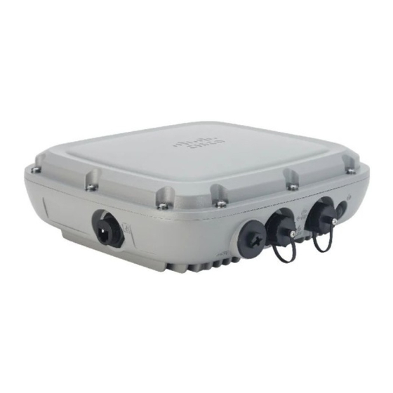
Cisco Catalyst 9124AX Series Outdoor Access Point Hardware
Installation Guide
First Published: 2021-03-29
Last Modified: 2021-07-09
Americas Headquarters
Cisco Systems, Inc.
170 West Tasman Drive
San Jose, CA 95134-1706
USA
http://www.cisco.com
Tel: 408 526-4000
800 553-NETS (6387)
Fax: 408 527-0883
o cerca il tuo prodotto tra le
migliori offerte di Altri dispositivi di rete
Cisco Catalyst
Advertisement
Table of Contents

Subscribe to Our Youtube Channel
Related Manuals for Cisco C9124AXE-E


Summary of Contents for Cisco C9124AXE-E
- Page 1 Questo manuale d’istruzione è fornito da trovaprezzi.it. Scopri tutte le offerte per Cisco Catalyst 9124AX C9124AXE-E o cerca il tuo prodotto tra le migliori offerte di Altri dispositivi di rete Cisco Catalyst 9124AX Series Outdoor Access Point Hardware Installation Guide First Published: 2021-03-29 Last Modified: 2021-07-09 Americas Headquarters Cisco Systems, Inc.
- Page 2 Cisco has more than 200 offices worldwide. Addresses and phone numbers are listed on the Cisco website at www.cisco.com/go/offices. Cisco and the Cisco logo are trademarks or registered trademarks of Cisco and/or its affiliates in the U.S. and other countries. To view a list of Cisco trademarks, go to this URL: https://www.cisco.com/c/en/us/about/legal/trademarks.html.
-
Page 3: Table Of Contents
C9124AXE (External Antenna) Model: Antenna Radiation Patterns Supported External Antennas Power Sources Power Injectors Ethernet (PoE) Ports C H A P T E R 3 Unpacking Your Access Point Package Contents Cisco Catalyst 9124AX Series Outdoor Access Point Hardware Installation Guide... - Page 4 Installing a CAT 5e Ethernet Cable and Gland Assembly to the Access Point Installing a CAT 6/6A Ethernet Cable and Gland Assembly to the Access Point Connecting a Fiber-optic Cable to the AP (AIR-SFP-KIT1=) Cisco Catalyst 9124AX Series Outdoor Access Point Hardware Installation Guide...
- Page 5 Declaration of Conformity for RF Exposure Generic Discussion on RF Exposure This Device Meets International Guidelines for Exposure to Radio Waves This Device Meets FCC Guidelines for Exposure to Radio Waves Cisco Catalyst 9124AX Series Outdoor Access Point Hardware Installation Guide...
- Page 6 This Device Meets the Industry Canada Guidelines for Exposure to Radio Waves Cet appareil est conforme aux directives internationales en matière d'exposition aux fréquences radioélectriques Additional Information on RF Exposure Declaration of Conformity Statements Cisco Catalyst 9124AX Series Outdoor Access Point Hardware Installation Guide...
-
Page 7: Preface
Communications, Services, and Additional Information, on page viii About this Guide This guide provides instructions to install your Cisco Access Point and provides links to resources that can help you configure it. This guide also provides mounting instructions and troubleshooting information. -
Page 8: Related Documentation
A warning symbol precedes each warning statement. Related Documentation All user documentation for the Cisco Catalyst 9124AX series access point is available at the following URL: https://www.cisco.com/c/en/us/support/wireless/catalyst-9124ax-series/series.html For detailed information and guidelines for configuring and deploying your access point in a wireless network, see the following documentation: •... -
Page 9: About The Cisco Catalyst 9124Ax Series Outdoor Access Point
Introduction to Cisco Catalyst 9124AX Series Outdoor Access Point Cisco Catalyst 9124AX Series Outdoor Access Point is a Wi-Fi 6 technology based outdoor access point. This access point (AP) series has three models: • Cisco Catalyst 9124AXI AP with omni antennas •... - Page 10 • Integrated Bluetooth Low Energy (BLE) radio enables IoT use cases such as location tracking and wayfinding. • Cisco RF ASIC, a fully integrated Software Defined Radio (SDR), can perform advanced radio frequency (RF) spectrum analysis, and deliver features such as next-generation CleanAir, Wireless Intrusion Prevention System (WIPS), Dynamic Frequency Selection (DFS) detection.
-
Page 11: Ap Model Numbers And Regulatory Domains
About the Cisco Catalyst 9124AX Series Outdoor Access Point AP Model Numbers and Regulatory Domains • Cisco DNA Center support enables Cisco DNA Spaces, Apple FastLane, and Cisco Identity Services Engine (ISE). • Optimized AP Roaming to ensure that client devices associate with the AP in their coverage range, which offers the fastest data rate available. -
Page 12: Antennas And Radios
You must verify whether the AP model you have is approved for use in your country. To verify approval and to identify the regulatory domain that corresponds to a particular country, visit http://www.cisco.com/go/aironet/compliance. Not all regulatory domains have been approved. As and when they are approved, the compliance list is updated. - Page 13 • 5G Radio1 - 2TX x 2RX; 2SS for channel bandwidth <= 80MHz • 5G Radio2 - 2TX x 2RX; 2SS for channel bandwidth <= 80MHz • 2G Radio - 2TX x 2RX; 2SS for 20 MHz only Cisco Catalyst 9124AX Series Outdoor Access Point Hardware Installation Guide...
- Page 14 About the Cisco Catalyst 9124AX Series Outdoor Access Point Antennas and Radios Cisco Catalyst 9124AX Series Outdoor Access Point Hardware Installation Guide...
-
Page 15: Hardware Features
Access Point Views, Ports, and Connectors Cisco Catalyst 9124AX Series Outdoor AP has multiple options that you can use to power the AP or join the AP to the controller. For information about connectors and ports for the AP models, see... - Page 16 So all data packets going out of the AP, including the 802.1x packets use the wired0 MAC address. The only exception is the CDP and LLDP packets that would use the wired1 MAC address as the source-MAC. Cisco Catalyst 9124AX Series Outdoor Access Point Hardware Installation Guide...
- Page 17 This port supports SIA. C9124AXE Connectors and Ports on the Base Figure 3: Model C9124AXE Base Connectors and Ports Port 1 1 Gig PSE (PoE-OUT) Ethernet Port This port supports SIA. Cisco Catalyst 9124AX Series Outdoor Access Point Hardware Installation Guide...
- Page 18 So all data packets going out of the AP, including the 802.1x packets use the wired0 MAC address. The only exception is the CDP and LLDP packets that would use the wired1 MAC address as the source-MAC. Cisco Catalyst 9124AX Series Outdoor Access Point Hardware Installation Guide...
-
Page 19: C9124Axi (Internal Antenna) Model: Antenna Radiation Patterns
Figure 4: Models C9124AXI, C9124AXD, and C9124AXE Left Side and Right Side Connectors and Ports Console Port Grounding Pad DC Power In C9124AXI (Internal Antenna) Model: Antenna Radiation Patterns The following illustrations show the C9124AXI model with internal antenna radiation patterns: Cisco Catalyst 9124AX Series Outdoor Access Point Hardware Installation Guide... - Page 20 Figure 6: C9124AXI Dual-Band Antenna Radiation Pattern (2.4 GHz Azimuth) Elevation) Figure 7: C9124AXI Dual-Band Antenna Radiation Pattern (5 GHz Figure 8: C9124AXI Dual-Band Antenna Radiation Pattern (5 GHz Azimuth) Elevation) Cisco Catalyst 9124AX Series Outdoor Access Point Hardware Installation Guide...
- Page 21 Figure 10: C9124AXI IoT Antenna Radiation Pattern (2.4 GHz Azimuth) Elevation) Figure 11: C9124AXI AUX RF ASIC Antenna Radiation Pattern Figure 12: C9124AXI AUX RF ASIC Antenna Radiation Pattern (2.4 GHz Azimuth) (2.4 GHz Elevation) Cisco Catalyst 9124AX Series Outdoor Access Point Hardware Installation Guide...
-
Page 22: C9124Axd (Directional Antenna) Model: Antenna Radiation Patterns
Figure 14: C9124AXI AUX RF ASIC Antenna Radiation Pattern (5 GHz (5 GHz Azimuth) Elevation) C9124AXD (Directional Antenna) Model: Antenna Radiation Patterns The C9124AXD model with directional internal antenna has its radio radiation patterns shown in the following images: Cisco Catalyst 9124AX Series Outdoor Access Point Hardware Installation Guide... - Page 23 Figure 16: C9124AXD Dual-Band Antenna Radiation Pattern (2.4 GHz Azimuth) (2.4 GHz Elevation) Figure 17: C9124AXD Dual-Band Antenna Radiation Pattern (5 GHz Figure 18: C9124AXD Dual-Band Antenna Radiation Pattern (5 GHz Azimuth) Elevation) Cisco Catalyst 9124AX Series Outdoor Access Point Hardware Installation Guide...
- Page 24 Figure 20: C9124AX IoT Antenna Radiation Pattern (2.4 GHz Azimuth) Elevation) Figure 21: C9124AXD AUX RF ASIC Antenna Radiation Pattern Figure 22: C9124AXD AUX RF ASIC Antenna Radiation Pattern (2.4 GHz Azimuth) (2.4 GHz Elevation) Cisco Catalyst 9124AX Series Outdoor Access Point Hardware Installation Guide...
-
Page 25: C9124Axe(Externalantenna)Model:antennaradiationpatterns
The following illustrations show the C9124AXE model with external antenna radiation patterns: Figure 25: AIR-ANT2413P2M-N: 2.4 GHz Dual-Polarized Two Port Figure 26: AIR-ANT2413P2M-N: 2.4 GHz Dual-Polarized Two Port Directional Antenna Radiation Pattern (Azimuth) Directional Antenna Pattern (Elevation) Cisco Catalyst 9124AX Series Outdoor Access Point Hardware Installation Guide... - Page 26 Figure 28: AIR-ANT2450V-N: 2.4 GHz Omnidirectional Antenna Radiation Pattern (Azimuth) Radiation Pattern (Elevation) Figure 29: AIR-ANT2480V-N: 2.4 GHz Omnidirectional Antenna Figure 30: AIR-ANT2480V-N: 2.4 GHz Omnidirectional Antenna Radiation Pattern (Azimuth) Radiation Pattern (Elevation) Cisco Catalyst 9124AX Series Outdoor Access Point Hardware Installation Guide...
- Page 27 Diverse-Array Radiation Pattern (Azimuth) Diverse-Array Antenna Radiation Pattern (Elevation) Figure 33: AIR-ANT2513P4M-NS: Four-Port Dual-Band Polarization Figure 34: AIR-ANT2513P4M-NS: Four-Port Dual-Band Polarization Diverse-Array Antenna SIA Radiation Pattern (Azimuth) Diverse-Array Antenna SIA Radiation Pattern (Elevation) Cisco Catalyst 9124AX Series Outdoor Access Point Hardware Installation Guide...
- Page 28 Figure 36: AIR-ANT2547VG-N: Dual-Band Omnidirectional Antenna Radiation Pattern (Azimuth) Radiation Pattern (Elevation) Figure 37: AIR-ANT2547VG-NS: Dual-Band Omnidirectional Antenna Figure 38: AIR-ANT2547VG-NS: Dual-Band Omnidirectional Antenna Radiation Pattern (Azimuth) Radiation Pattern (Elevation) Cisco Catalyst 9124AX Series Outdoor Access Point Hardware Installation Guide...
- Page 29 Figure 40: AIR-ANT2568VG-N: Dual-Band Omnidirectional Antenna Radiation Pattern (Azimuth) Radiation Pattern (Elevation) Figure 41: AIR-ANT2568VG-NS: Dual-Band Omnidirectional Antenna Figure 42: AIR-ANT2568VG-NS: Dual-Band Omnidirectional Antenna Radiation Pattern (Azimuth) Radiation Pattern (Elevation) Cisco Catalyst 9124AX Series Outdoor Access Point Hardware Installation Guide...
- Page 30 Polarization-Diverse Patch Antenna Radiation Pattern (Elevation) Figure 45: AIR-ANT2588P4M-NS: 4-Port Dual-Band Figure 46: AIR-ANT2588P4M-NS: 4-Port Dual-Band Polarization-Diverse Patch Antenna, SIA Radiation Pattern Polarization-Diverse Patch Antenna, SIA Radiation Pattern (Azimuth) (Elevation) Cisco Catalyst 9124AX Series Outdoor Access Point Hardware Installation Guide...
-
Page 31: Supported External Antennas
Figure 49: AIR-ANT5180V-N: 5 GHz Omnidirectional Antenna Figure 50: AIR-ANT5180V-N: 5 GHz Omnidirectional Antenna Radiation Pattern (Azimuth) Radiation Pattern (Elevation) Supported External Antennas The following table shows the external antennas supported by the C9124AXE access point Cisco Catalyst 9124AX Series Outdoor Access Point Hardware Installation Guide... - Page 32 Table 2: 9124AXE Access Point Supported External Antennas Antenna Gain Antenna Name (dBi) 2.4–GHz 5–GHz AIR-ANT2547V-N Cisco Aironet Dual-Band Omnidirectional Colinear Array Antenna (White) Connectors: N-Male AIR-ANT2547VG-N Cisco Aironet Dual-Band Omnidirectional Colinear Array Antenna (Gray) Connectors: N-Male Cisco Catalyst 9124AX Series Outdoor Access Point Hardware Installation Guide...
- Page 33 For installation instructions and detailed information on any of these antennas, refer to the antenna guide at: http://www.cisco.com/c/en/us/support/wireless/aironet-antennas-accessories/ products-installation-guides-list.html Follow all safety precautions when installing the antennas. For information on safety, see Safety Precautions when Installing Antennas, on page Cisco Catalyst 9124AX Series Outdoor Access Point Hardware Installation Guide...
-
Page 34: Power Sources
Cisco does not recommend any third-party antennas, and Cisco Technical Assistance Center will not be able to provide any support for third-party antennas. Cisco’s FCC Part 15 compliance is only guaranteed with Cisco antennas or antennas that are of the same design and gain as Cisco antennas. -
Page 35: Ethernet (Poe) Ports
The Ethernet cable must be a shielded, outdoor rated, Category 5e (CAT 5e) or better cable. The AP senses the Ethernet and power signals and automatically switches internal circuitry to match the cable connections. Cisco Catalyst 9124AX Series Outdoor Access Point Hardware Installation Guide... - Page 36 Hardware Features Ethernet (PoE) Ports Cisco Catalyst 9124AX Series Outdoor Access Point Hardware Installation Guide...
-
Page 37: Unpacking Your Access Point
Return the packing material to the shipping container and save it for future use. Step 3 Verify that you have received following items: • The access point • Accessory kit (Ethernet port termination plug, ground lug kit) Cisco Catalyst 9124AX Series Outdoor Access Point Hardware Installation Guide... -
Page 38: Optional Tools And Hardware From Cisco
Optional Tools and Hardware from Cisco • (Optional) Mounting brackets only if you opted for these when ordering the AP. If any item is missing or damaged, contact your Cisco representative or reseller for instructions. Optional Tools and Hardware from Cisco Depending on what you ordered, the following optional equipment may be part of your shipment: •... - Page 39 Power Supply Description AIR-PWRINJ-60RGD1= 60W rated outdoor power injector, with North America AC plug AIR-PWRINJ-60RGD2= 60W rated outdoor power injector, global version without AC plug AIR-PWRINJ6= 30W rated single-port PoE injector Cisco Catalyst 9124AX Series Outdoor Access Point Hardware Installation Guide...
-
Page 40: Preinstallation Checks And Installation Guidelines
Typical Access Point Installation Components The Cisco Catalyst 9124AX Series Outdoor Access Point is designed to be installed in an outdoor environment, such as the exterior roof overhang of a tall building or a streetlight pole. Carefully review the... - Page 41 Power cord better) cable Water drip loop Power injector 6-AWG copper grounding wire Shielded Ethernet (CAT5e or better) cable Ground rod Controller (through a switch) Independently sourced by the user. Cisco Catalyst 9124AX Series Outdoor Access Point Hardware Installation Guide...
- Page 42 Unpacking Your Access Point Typical Access Point Installation Components Cisco Catalyst 9124AX Series Outdoor Access Point Hardware Installation Guide...
-
Page 43: Installation Overview
Mounting the Access Point, on page 38 section. • AP power options: 802.3at (PoE+), 802.3bt, and Cisco Universal PoE (Cisco UPOE) Note When you use 802.3af to power an AP, both the 2.4-GHz and 5-GHz radios are disabled, and the Ethernet gets downgraded to 1–GbE speeds. -
Page 44: Performing A Preinstallation Configuration (Optional)
Deploying the Access Point in a Wireless Network, on page The preinstallation configuration setup is illustrated in Figure 52: Preinstallation Configuration Setup, on page Figure 52: Preinstallation Configuration Setup To perform preinstallation configuration, follow these steps: Cisco Catalyst 9124AX Series Outdoor Access Point Hardware Installation Guide... - Page 45 Procedure Step 1 Ensure that the Cisco Controller Distribution System port is connected to the network. Use the procedure for the CLI or the GUI interface, as described in the release appropriate Cisco Controller Configuration guide. To use an SFP module, you must insert it into an AP's SFP port before the AP boots, in order to Note ensure correct power consumption and PoE derating.
-
Page 46: Mounting The Access Point
2 to 5 inch (51 to 127 mm). See: Vertically Mounting the AP to a Wall, on page 40 Vertically Mounting the AP to a Pole, on page 42 Cisco Catalyst 9124AX Series Outdoor Access Point Hardware Installation Guide... - Page 47 Strand Mounting the AP, on page 60 Mount the AP using no less than four screw holes on a bracket. For the AIR-MNT-STRAND1= bracket, use no less than two screws. Cisco Catalyst 9124AX Series Outdoor Access Point Hardware Installation Guide...
-
Page 48: Vertically Mounting The Ap To A Wall
One of four slots for steel band clamps, used for pole mounting only. Bracket mount holes for fastening bracket to the wall. You can use bolts of up to 1/4” or 6 mm in diameter. Cisco Catalyst 9124AX Series Outdoor Access Point Hardware Installation Guide... - Page 49 Drill bit for wall anchors Electric drill and standard screwdriver #6 AWG ground wire Shielded outdoor-rated Ethernet (CAT5e or better) cable Grounding block Grounding rod 10–mm box-end wrench or socket set Cisco Catalyst 9124AX Series Outdoor Access Point Hardware Installation Guide...
-
Page 50: Vertically Mounting The Ap To A Pole
This kit can be used to install the AP on a pole or mast. It supports metal, wood, or fiberglass poles of 2 to 5 inches (51 to 127 mm) in diameter. Cisco Catalyst 9124AX Series Outdoor Access Point Hardware Installation Guide... - Page 51 Supplied in the Kit? One wall mount bracket Four M6 x12 mm hex head bolts Two stainless steel band clamps (adjustable 2 to 5 inch (51 to 127 mm) 10–mm box-end wrench Cisco Catalyst 9124AX Series Outdoor Access Point Hardware Installation Guide...
-
Page 52: Vertically Mounting The Ap With Dc Supply To A Wall
You can use the mounting bracket as a template to mark the mounting holes' positions for your installation, install the mounting bracket, and then attach the AP to the bracket. Caution The mounting wall, attaching screws, and wall anchors must support a 50-lb (22.7–kg) static weight. Cisco Catalyst 9124AX Series Outdoor Access Point Hardware Installation Guide... - Page 53 Four #8-32 screws to mount the power supply Crimping tool for ground lug, Panduit CT-720 with CD-720-1 die Four wall mounting screws #6 AWG ground wire Shielded outdoor-rated Ethernet (CAT5e or better) cable Grounding block Cisco Catalyst 9124AX Series Outdoor Access Point Hardware Installation Guide...
-
Page 54: Vertically Mounting The Ap With Dc Supply To A Pole
The AIR-MNT-VERT2= fixed mounting kit contains a mounting bracket for both wall-mounting and pole-mounting, the AP, along with the power supply kit. This mounting kit supports metal, wood, or fiberglass poles from 2 to 5 inch (51 to 127 mm) in diameter. Cisco Catalyst 9124AX Series Outdoor Access Point Hardware Installation Guide... - Page 55 One wall mount bracket Four M6 x12 mm hex head bolts Four #8-32 screws to mount the power supply Three stainless steel band clamps (adjustable 2 to 5 inch (51 to 127 mm) Cisco Catalyst 9124AX Series Outdoor Access Point Hardware Installation Guide...
-
Page 56: Articulating Mount For The Ap To A Wall Or Ceiling
This kit allows for adjusting the position of the AP by pivoting the AP along its vertical plane. You can also, using this kit, mount the AP to a ceiling in a horizontal plane. Cisco Catalyst 9124AX Series Outdoor Access Point Hardware Installation Guide... - Page 57 This is the AP-plate end of the bracket and is steel band clamps in pole-mount installations. fastened to the back of the AP. Wall-plate end of the bracket. This plate is fastened to the wall. Cisco Catalyst 9124AX Series Outdoor Access Point Hardware Installation Guide...
- Page 58 Pole-mount screw clamp M8 spring washer Pivoting bracket base plate M8 nut Before you begin Ensure that you have the following materials before beginning to mount the AP to a wall: Cisco Catalyst 9124AX Series Outdoor Access Point Hardware Installation Guide...
- Page 59 It is important to use proper anchoring for the mount surface to support the static load. Step 4 Align the AP-plate end of the bracket with the screw holes in the AP's back. Cisco Catalyst 9124AX Series Outdoor Access Point Hardware Installation Guide...
-
Page 60: Articulating Mount For The Ap To A Pole
The AIR-MNT-ART1= articulating mounting kit allows for adjusting the AP position by pivoting the AP along its vertical plane. Figure 61: AP Pole Mounted Using the Pivoting Mounting Bracket One of four mounting holes for mounting the Steel band clamps AP to the bracket Cisco Catalyst 9124AX Series Outdoor Access Point Hardware Installation Guide... - Page 61 Pivoting mount kit and hardware (8) M6 x 12-mm Hex-head Bolts Adapter bracket for option horizontal mount Two stainless steel band clamps (adjustable 2 to 5 inch (51 to 127mm) Cisco Catalyst 9124AX Series Outdoor Access Point Hardware Installation Guide...
- Page 62 Tighten the M8 x 80 mm bolts to 52 to 61 lbf-in (5.9 to 6.9 Nm) of torque. Caution Misalignment and over-torquing can result in breaking the screw clamp. Cisco Catalyst 9124AX Series Outdoor Access Point Hardware Installation Guide...
-
Page 63: Wall Mounting The Ap With Horizontal Kit
63: Wall mount L-bracket screw hole dimensions, on page 56 for the mounting bracket screw hole locations and dimensions. See Figure 64: L-bracket AP mount dimensions, on page 56 for dimensions of the mounting L-bracket. Cisco Catalyst 9124AX Series Outdoor Access Point Hardware Installation Guide... - Page 64 We recommend you install the solar shield. However, if the AP's installed location is shaded from Note the sun (For example: indoors or under an eave), the solar shield is not required. Cisco Catalyst 9124AX Series Outdoor Access Point Hardware Installation Guide...
-
Page 65: Pole Mounting The Ap With Horizontal Kit
Ensure that you have the following materials before beginning to mount the AP horizontally to a pole: Table 10: Materials Needed for Mounting the AP using AIR-MNT-HORZ1= Kit Materials Required Supplied in the Kit? Wall/Pole Mount L-Bracket Solar Shield Cisco Catalyst 9124AX Series Outdoor Access Point Hardware Installation Guide... - Page 66 We recommend you install the solar shield. However, if the AP's installed location is shaded from the sun (For example: indoors or under an eave), the solar shield is not required. Cisco Catalyst 9124AX Series Outdoor Access Point Hardware Installation Guide...
-
Page 67: Dc Supply Mount Bracket
The AIR-ACC-PS-MNT1= bracket is an orderable option to mount a DC supply to the AIR-MNT-HORZ1= L-bracket kit. Figure 66: Installing the DC supply bracket on to the L-bracket DC supply mount bracket 8-32 x 0.62 lg Bracket screws DC Supply Cisco Catalyst 9124AX Series Outdoor Access Point Hardware Installation Guide... -
Page 68: Strand Mounting The Ap
2 to 3-inch (51 to 76-mm) cable bundle between the support cable strand and the AP's back surface. The SMK can also accommodate up to 10 degrees of strand or cable droop. Figure 68: SMK Bracket Assembly Dimensions with Mounted AP Cisco Catalyst 9124AX Series Outdoor Access Point Hardware Installation Guide... - Page 69 5/16-18 x 1.25 inchBolt 5/16-18 x 0.75” Bolt Cable Clamp Figure 70: Assembling the AP to the SMK and Solar Shield SMK Bracket Assembly M8 split lock washer Solar Shield M8 flat washer Cisco Catalyst 9124AX Series Outdoor Access Point Hardware Installation Guide...
- Page 70 Place the cable bracket, attached to the AP, on the cable strand, with each pair of cable clamps clamping on to the cable strand. Tighten the cable clamps by tightening the two 5/16”–18 nuts to 13 to 15 lb-ft (17.6 to 20.3 Nm) of torque. Cisco Catalyst 9124AX Series Outdoor Access Point Hardware Installation Guide...
-
Page 71: Ap Paintable Cover Kit
You can install the cover before or after all connections are completed. However, if you require to install the remote cabled antennas, the shield may need to be installed before the antenna cables are attached to the AP. Figure 72: AP with Paintable Cover Kit Cisco Catalyst 9124AX Series Outdoor Access Point Hardware Installation Guide... -
Page 72: Installing A Lightning Arrestor
Overvoltage transients can be created through lightning static discharges, switch processes, direct contact with power lines, or through earth currents. The Cisco Aironet AIR-ACC245LA-N Lightning Arrestor limits the amplitude and duration of disturbing interference voltages and improves the over voltage resistance of in-line equipment, systems, and components. -
Page 73: Lightning Arrestor Installation Notes
Lightning Arrestor Installation Notes Installation Considerations Cisco recommends that you bulkhead mount the lightning arrestor so it can be installed as a wall-feed through on the wall of the protected space. The importance of obtaining a good ground and bonding connection cannot be overstressed. Consider these points when grounding the lightning arrestor: •... -
Page 74: Grounding The Access Point
(the longer the run, the greater the loss). Cisco recommends a high-quality, low-loss cable for use with the lightning arrestor. Grounding the Access Point The AP must be grounded before connecting power. -
Page 75: Powering The Access Point
The supporting outdoor power injectors are AIR-PWRINJ-60RGD1 and AIR-PWRINJ-60RGD2 rated at 60W each. These power injectors support 10/100/1000BASE-T operation only. They do not support the 2.5GBAST-T (mGig) Ethernet speed. Table 12: Cisco Catalyst 9124AX AP Reduced Power Feature Matrix PoE-in/DC Radio 0... -
Page 76: Connecting A Power Injector
Statement 1023 Note The installer is responsible for ensuring that powering the AP from this type of power injector is allowed by local and/or national safety and telecommunications equipment standards. Cisco Catalyst 9124AX Series Outdoor Access Point Hardware Installation Guide... -
Page 77: Connecting A Dc Power Cable To The Access Point
Do not discard the cap unless you are sure the port will never need to be sealed in the future. See the following image for the location of the DC power connector. Cisco Catalyst 9124AX Series Outdoor Access Point Hardware Installation Guide... - Page 78 2-Pin DC plug Step 5 If the AP is to be power with customer supplied DC source. The following steps show how to terminate the Cisco-supplied DC plug to the cable. Cisco Catalyst 9124AX Series Outdoor Access Point Hardware Installation Guide...
- Page 79 Push to be sure the pin is fully seated into the barrel. Pin 1 (+V) Pin 2 (-V), the connector body is marked (+) and (-) to show polarity pin assignments. Note Cisco Catalyst 9124AX Series Outdoor Access Point Hardware Installation Guide...
-
Page 80: Connecting Data Cables
Installing a CAT 5e Ethernet Cable and Gland Assembly to the Access Point Figure 80: CAT 5e Cable Gland Assembly CAT 5e RJ45 Plug Screw nut Gasket Seal Clamp ring Thread-lock sealing nut Cisco Catalyst 9124AX Series Outdoor Access Point Hardware Installation Guide... - Page 81 Route your Ethernet cable and cut off any excess cable. Step 12 Install an RJ45 connector on the unterminated cable end and insert it into the power injector. Step 13 Turn on the power to the power injector. Cisco Catalyst 9124AX Series Outdoor Access Point Hardware Installation Guide...
-
Page 82: Installing A Cat 6/6A Ethernet Cable And Gland Assembly To The Access Point
Step 2 Ensure a 6 AWG ground wire is connected to the AP (see Grounding the Access Point, on page 66). Step 3 Remove the covering cap from the PoE port. Cisco Catalyst 9124AX Series Outdoor Access Point Hardware Installation Guide... -
Page 83: Connecting A Fiber-Optic Cable To The Ap (Air-Sfp-Kit1=)
Turn on the power to the power injector. Connecting a Fiber-optic Cable to the AP (AIR-SFP-KIT1=) The optional Cisco accessory fiber-optic kit enables the AP to support fiber-optic network connections. You can connect the fiber-optic networking cable to the SFP port. The small form-factor pluggable (SFP) transceiver module connects the cable to the SFP port. - Page 84 • Adjustable wrench Procedure Step 1 Disconnect all power sources from the AP. Step 2 Remove the plug from the SFP port by following the guidelines given in this step. Cisco Catalyst 9124AX Series Outdoor Access Point Hardware Installation Guide...
- Page 85 Insert the SFP module into the SFP port and ensure that it latches properly. Step 4 Loosen and dis-assemble the SFP adapter gland components. Figure 84: Exploded view of Fiber-Optic cable and Gland assembly SFP Transceiver Module Gland Compression Ferrule Cisco Catalyst 9124AX Series Outdoor Access Point Hardware Installation Guide...
- Page 86 Inspect that the body is seated correctly. Using an adjustable wrench, tighten the body snugly to the AP body to approximately 13 to 17 lb-in (15 to 20 kgf-cm) of torque. Cisco Catalyst 9124AX Series Outdoor Access Point Hardware Installation Guide...
-
Page 87: Powering The Access Point Over Power-Over-Ethernet
Powering the Access Point over Power-over-Ethernet The AP can be powered through Power-over-Ethernet (PoE) using the following: • 802.3at (PoE+): Any 802.3at (30W) compliant switch port or Cisco Power Injector AIR-PWRINJ6= • 802.3bt: Any 802.3bt compliant switch port or IEEE 802.3bt compliant Power Injector •... - Page 88 Installation Overview Powering the Access Point over Power-over-Ethernet Cisco Catalyst 9124AX Series Outdoor Access Point Hardware Installation Guide...
-
Page 89: Configuring And Deploying The Access Point
Checking the Access Point LEDs, on page 82 Controller Discovery Process The Cisco AP must join a controller to function as an AP and start serving clients. Cisco uses a process called controller discovery process to join a controller. The devices use Lightweight Access Point Protocol (LWAPP) to communicate with each other. -
Page 90: Deploying The Access Point In A Wireless Network
When an AP receives an IP address and DNS information from a DHCP server, it contacts the DNS to resolve CISCO-CAPWAP-CONTROLLER.localdomain. When the DNS sends a list of controller IP addresses, the AP sends discovery requests to the controllers. - Page 91 There is an Ethernet failure or an image recovery (the Reset button has been pushed for 20-30 seconds) Blinking Green Image recovery is in progress (the Reset button has been released) Cisco Catalyst 9124AX Series Outdoor Access Point Hardware Installation Guide...
- Page 92 Configuring and Deploying the Access Point Checking the Access Point LEDs Cisco Catalyst 9124AX Series Outdoor Access Point Hardware Installation Guide...
-
Page 93: Troubleshooting
You can configure the syslog server for APs and view the AP join information only from the controller CLI interface. Important Information for Controller-based Deployments Keep these guidelines in mind when you use the AP: • The AP can only communicate with Cisco controllers. Cisco Catalyst 9124AX Series Outdoor Access Point Hardware Installation Guide... -
Page 94: Configuring Dhcp Option 43
DHCP Option 43 is limited to one AP type per DHCP pool. You must configure a separate DHCP pool for each AP type. The Cisco Catalyst 9124AX Series Outdoor AP uses the type-length-value (TLV) format for DHCP Option 43. DHCP servers must be programmed to return the option based on the AP DHCP Vendor Class Identifier (VCI) string (DHCP Option 43). - Page 95 10.127.127.2. The type is f1(hex). The length is 2 * 4 = 8 = 08 (hex). The IP addresses translate to 0a7e7e02 and 0a7f7f02. Assembling the string then yields f1080a7e7e020a7f7f02. The resulting Cisco IOS command added to the DHCP scope is option 43 hex f1080a7e7e020a7f7f02.
- Page 96 Troubleshooting Configuring DHCP Option 43 Cisco Catalyst 9124AX Series Outdoor Access Point Hardware Installation Guide...
-
Page 97: Safety Guidelines And Warnings
Safety Guidelines and Warnings Translated versions of the following safety warnings are provided in the translated safety warnings document shipped with your AP. The translated warnings are also in the Translated Safety Warnings for Cisco Catalyst Access Points, available on Cisco.com. - Page 98 Ultimate disposal of this product should be handled according to all national laws and regulations. Statement 1040 Danger When installing or replacing the unit, the ground connection must always be made first and disconnected last. Statement 1046. Danger Class 1 Laser Product. Statement 1008 Cisco Catalyst 9124AX Series Outdoor Access Point Hardware Installation Guide...
- Page 99 Electrical Code, Part 1, CSA C22.2. External power supply, power adapter and/or power injector, if provided, are not suitable for installation in air spaces. Statement 440 • FCC Safety Compliance Statement, on page 92 • Safety Precautions, on page 92 Cisco Catalyst 9124AX Series Outdoor Access Point Hardware Installation Guide...
-
Page 100: Fcc Safety Compliance Statement
The FCC, with its action in ET Docket 96-8, has adopted a safety standard for human exposure to RF electromagnetic energy emitted by FCC-certified equipment. When used with approved Cisco antennas, Cisco Catalyst products meet the uncontrolled environmental limits found in OET-65 and ANSI C95.1, 1991. Proper operation of this radio device according to the instructions in this publication results in user exposure substantially below the FCC recommended limits. -
Page 101: Safety Precautions When Installing Antennas
Code, Article 810, Canada: Canadian Electrical Code, Section 54). Statement 280 • Before you install an antenna, contact your Cisco account representative to explain which mounting method to use for the size and type of antenna that you are about to install •... -
Page 102: Performing Site Surveys
• Data rates: Sensitivity and range are inversely proportional to data bit rates. The maximum radio range is achieved at the lowest workable data rate. A decrease in receiver sensitivity occurs as the radio data increases. Cisco Catalyst 9124AX Series Outdoor Access Point Hardware Installation Guide... - Page 103 • Have you configured the APs before you go onsite? It is always easier to resolve configurations or device problems first. • Do you have the proper tools and equipment to complete your survey? Cisco Catalyst 9124AX Series Outdoor Access Point Hardware Installation Guide...
- Page 104 Safety Guidelines and Warnings Performing Site Surveys Cisco Catalyst 9124AX Series Outdoor Access Point Hardware Installation Guide...
-
Page 105: Declarations Of Conformity And Regulatory Information
C H A P T E R Declarations of Conformity and Regulatory Information This section provides declarations of conformity and regulatory information for the Cisco Catalyst 9124AX Series Outdoor APs. You can find additional information at this URL: http://www.cisco.com/go/aironet/ compliance. -
Page 106: Operation Of Cisco Catalyst Access Points In México
The Part 15 radio device operates on a non-interference basis with other devices operating at this frequency when using the integrated antennas. Any changes or modification to the product not expressly approved by Cisco could void the user’s authority to operate this device. Operation of Cisco Catalyst Access Points in México Declaración para México... -
Page 107: Guidelines For Operating Cisco Catalyst Access Points In Japan
Danger Guidelines for Operating Cisco Catalyst Access Points in Japan This section provides guidelines for avoiding interference when operating Cisco Catalyst access points in Japan. These guidelines are provided in both Japanese and English. English Translation... -
Page 108: Statement 371-Power Cable And Ac Adapter
Safety Law prohibits the use of UL-certified cables (that have the “UL” shown on the code) for any other electrical devices than products designated by CISCO. The use of cables that are certified by Electrical Appliance and Material Safety Law (that have “PSE” shown on the code) is not limited to CISCO-designated products. - Page 109 2.4 GHz—7 50 ohms 5 GHz—7 dBi List of Internal Antennas Supported on C9124AXD Antenna Type Antenna Gain Antenna Impedance Single-Port Single-Band omni (Mixed POL) 4 dBi 50 ohms BLE/IOT Cisco Catalyst 9124AX Series Outdoor Access Point Hardware Installation Guide...
- Page 110 Single–Band Omni 2.4 GHz—13 50 ohms Single–Band Omni 5 GHz—8 dBi 50 ohms Single–Band Omni 5 GHz—14 dBi 50 ohms Dual-Band Omni 2.4 GHz—4 dBi 50 ohms 5 GHz—7 dBi Cisco Catalyst 9124AX Series Outdoor Access Point Hardware Installation Guide...
-
Page 111: Industry Canada
This equipment is intended to be used in all EU and EFTA countries. Outdoor use may be restricted to certain frequencies and/or may require a license for operation. For more details, contact Cisco Corporate Compliance. The product carries the CE Mark:... -
Page 112: Administrative Rules For Cisco Catalyst Access Points In Taiwan
Administrative Rules for Cisco Catalyst Access Points in Taiwan Administrative Rules for Cisco Catalyst Access Points in Taiwan This section provides administrative rules for operating Cisco Catalyst APs in Taiwan. The rules for all access points are provided in both Chinese and English. -
Page 113: Operation Of Cisco Catalyst Access Points In Brazil
Operation of Cisco Catalyst Access Points in Brazil This section contains special information for operation of Cisco Catalyst APs in Brazil. Access Point Models Certification Number... -
Page 114: Declaration Of Conformity For Rf Exposure
This Device Meets International Guidelines for Exposure to Radio Waves The Cisco Catalyst 9124AX Series Outdoor AP device includes a radio transmitter and receiver. It is designed not to exceed the limits for exposure to radio waves (radio frequency electromagnetic fields) recommended by international guidelines. -
Page 115: This Device Meets Fcc Guidelines For Exposure To Radio Waves
This Device Meets FCC Guidelines for Exposure to Radio Waves The Cisco Catalyst 9124AX Series Outdoor AP device includes a radio transmitter and receiver. It is designed not to exceed the limits for exposure to radio waves (radio frequency electromagnetic fields) as referenced in FCC Part 1.1310. - Page 116 This Device Meets the Industry Canada Guidelines for Exposure to Radio Waves The Cisco Catalyst 9124AX Series Outdoor AP device includes a radio transmitter and receiver. It is designed not to exceed the limits for exposure to radio waves (radio frequency electromagnetic fields) as referenced in Health Canada Safety Code 6.
-
Page 117: Declaration Of Conformity Statements
Additional Information on RF Exposure You can find additional information on the subject at the following links: • Cisco Systems Spread Spectrum Radios and RF Safety white paper at this URL: http://www.cisco.com/warp/public/cc/pd/witc/ao340ap/prodlit/rfhr_wi.htm • FCC Bulletin 56: Questions and Answers about Biological Effects and Potential Hazards of Radio Frequency Electromagnetic Fields •... - Page 118 Declarations of Conformity and Regulatory Information Declaration of Conformity Statements Cisco Catalyst 9124AX Series Outdoor Access Point Hardware Installation Guide...
Need help?
Do you have a question about the C9124AXE-E and is the answer not in the manual?
Questions and answers