Cub Cadet SERIES 5000 5252 Operator's Manual
Series 5000
Hide thumbs
Also See for SERIES 5000 5252:
- Operator's manual (48 pages) ,
- Operator's manual (17 pages)
Table of Contents
Advertisement
Quick Links
Operator's Manual
IMPORTANT: READ SAFETY RULES AND INSTRUCTIONS CAREFULLY
Warning
: This unit is equipped with an internal combustion engine and should not be used on or near any unimproved
forest-covered, brush-covered or grass-covered land unless the engine's exhaust system is equipped with a spark
arrester meeting applicable local or state laws (if any). If a spark arrester is used, it should be maintained in effective
working order by the operator. In the State of California the above is required by law (Section 4442 of the California Public
Resources Code). Other states may have similar laws. Federal laws apply on federal lands. A spark arrester for the
muffler is available through your nearest engine authorized service dealer or contact the service department, P.O. Box
361131 Cleveland, Ohio 44136-0019.
CUB CADET LLC P.O. BOX 361131 CLEVELAND, OHIO 44136-0019 [www.cubcadet.com]
PRINTED IN U.S.A.
S
ERIES
TRACTOR
MODEL 5252
5000
FORM NO. 769-00867F
(5/05)
Advertisement
Table of Contents

Related Manuals for Cub Cadet SERIES 5000 5252


Summary of Contents for Cub Cadet SERIES 5000 5252
- Page 1 Resources Code). Other states may have similar laws. Federal laws apply on federal lands. A spark arrester for the muffler is available through your nearest engine authorized service dealer or contact the service department, P.O. Box 361131 Cleveland, Ohio 44136-0019. CUB CADET LLC P.O. BOX 361131 CLEVELAND, OHIO 44136-0019 [www.cubcadet.com] PRINTED IN U.S.A. 5000...
-
Page 2: Table Of Contents
The dealer has trained service personnel familiar with the latest servicing information, is equipped with the latest tools, and has a complete line of genuine Cub Cadet service parts which assure proper fit and high quality. -
Page 3: Recording Model And Serial Number Information
Serial Number ROPS Information Plate: ROPS Serial No. TRACTOR MODEL PLATE XXXXXXXXXXX XXXXXXXXXX Model Number Mfg. Date CUB CADET LLC P. O. BOX 361131 www.cubcadet.com CLEVELAND, OH 44136 DEALER LOCATOR PHONE NUMBER: 877-282-8684 Mfg. Date (Serial No.) Spec. No. Serial No. -
Page 4: Important Safe Operation Practices
IMPORTANT SAFE OPERATION PRACTICES WARNING: THIS SYMBOL POINTS OUT IMPORTANT SAFETY INSTRUCTIONS WHICH, IF NOT FOLLOWED, COULD ENDANGER THE PERSONAL SAFETY AND/OR PROPERTY OF YOURSELF AND OTHERS. READ AND FOLLOW ALL INSTRUCTIONS IN THIS MANUAL BEFORE ATTEMPTING TO OPERATE YOUR UNIT. FAILURE TO COMPLY WITH THESE INSTRUCTIONS MAY RESULT IN PERSONAL INJURY. -
Page 5: Slope Operation
Debris may build up on the mower deck or contact the engine exhaust presenting a potential fire hazard. • only accessories approved machine by Cub Cadet. Read, understand and follow instructions provided approved accessory. • Use the roll bar and seat belt for safe operation. -
Page 6: Operating The Pto
3. CHILDREN • Tragic accidents can occur if the operator is not alert to the presence of children. Children are often attracted to the machine. Never assume children will remain where you last saw them. • Keep children out of the mowing area and in watchful care of an adult other than the operator. - Page 7 • Keep all nuts, bolts and screws tight to be sure the equipment is in safe working condition. • Never tamper with safety devices. Check their proper operation regularly. • After striking a foreign object, stop the engine, and thoroughly inspect the mower for any damage.
-
Page 8: Safety Labels
SAFETY LABELS WARNING AVOID SERIOUS INJURY OR DEATH GO UP AND DOWN SLOPES, NOT ACROSS. AVOID SUDDEN TURNS. DO NOT OPERATE UNIT WHERE IT COULD SLIP OR TIP. IF MACHINE STOPS GOING UPHILL, STOP PTO AND BACK DOWN HILL SLOWLY. DO NOT MOW WHEN CHILDREN OR OTHERS ARE AROUND. -
Page 9: Section 1: Controls And Features
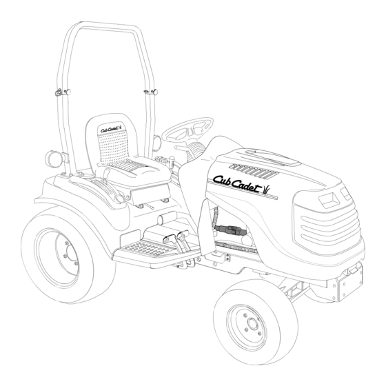
SECTION 1: CONTROLS AND FEATURES Steering Wheel Throttle Handle PTO Switch Ignition Switch Brake Pedal Reverse Pedal G. Forward Pedal * Steering Wheel, Seat, and ROPS Transparent for Clarity HOURS 1/10 FUEL x1000 Figure 1 Hand Holds Hydraulic Lift Lever Cup Holder Amber Hazzard Light Seat Adjustment Lever... - Page 10 NOTE: References to LEFT and RIGHT indicate that side of the tractor when facing forward while seated in the drivers seat. Reference to FRONT indicates the grille end of the tractor; to REAR, the tow plate end. A. Steering Wheel The steering wheel is centered on the dash panel, and used to change the direction (left or right) of the tractor while driving.
- Page 11 G. Forward Pedal Forward Pedal Symbol Figure 6 The forward control pedal is located on the right running board below the brake pedal. Slowly press down on the pedal to start moving forward. The forward ground speed of the tractor is directly affected by the distance the pedal is depressed.
- Page 12 S. Differential Lock Pedal Diff. Lock Pedal Symbol Figure 8 Located at the front of the left running board, the differential lock pedal engages the transmission differential lock. The differential lock is used to gain additional trac- tion when operating the tractor on wet or loose soil. When the pedal is depressed the rear wheels of the tractor are prevented from rotating independently of one another.
- Page 13 If the oil level is within the operating range, but the light remains on, contact your Cub Cadet dealer. NOTE: The oil pressure indicator may illuminate when the key switch is turned to the on position, but should turn off when the engine is started.
-
Page 14: Section 2: Operation
• In the event of an accident, have the ROPS carefully inspected and, if necessary, replaced by your Cub Cadet dealer. Do not attempt to repair the ROPS. FOLDING THE ROPS The foldable ROPS feature allows the operator to quickly lower the ROPS to operate in areas where there is low overhead clearance. - Page 15 If the interlock system should ever malfunction, do not operate the tractor. Contact your authorized Cub Cadet Dealer. The safety interlock system prevents the engine from cranking or starting unless the brake pedal is fully depressed, and the PTO is “OFF”.
- Page 16 If the noise continues, increase the engine speed to mid-throttle and allow the engine to run for several minutes. If the noise persists, contact your Cub Cadet dealer. WARNING: If the starter disengages the engine flywheel, but the engine does...
- Page 17 DRIVING THE TRACTOR WARNING: Avoid sudden starts, exces- sive speed and sudden stops. WARNING: Do not leave the seat of the tractor without disengaging the PTO and engaging the parking brake. If leaving the tractor unattended, turn the ignition key off and remove key. •...
- Page 18 USING THE HI/LO RANGE SHIFT LEVER WARNING: tractor stopped before engaging or disengag- ing the transmission Hi/Lo range shift lever. Shifting while the tractor is in motion will cause damage to the transmission. WARNING: Always maintain a tractor speed that allows for complete control and stability of the machine.
- Page 19 • Fully depress and hold the differential lock pedal to engage the transmission differential lock. Release the pedal to disengage the differential lock. See Figure 18. DIFFERENTIAL LOCK PEDAL (Depress and Hold to Engage) Figure 18 NOTE: Because of the drive load on the internal engagement mechanism, releasing the differential lock pedal...
- Page 20 USING THE PTO REVERSE OVERRIDE SWITCH The PTO reverse override switch, located on the left fender, allows the PTO to operate while the tractor is traveling in the reverse direction. See Figure 21. PTO REVERSE OVERRIDE SWITCH Figure 21 • The PTO should first be engaged using the PTO switch on the dash panel.
- Page 21 REMOVING THE REAR PTO COVER The rear PTO cover is a safety feature designed to prevent items from accidentally being caught by the rotating shaft. The cover should be removed only when the rear PTO is being utilized. To remove and reinstall the cover, proceed as follows: •...
- Page 22 To counterbalance three point hitch mounted equipment, a weight bracket/bumper kit and cast iron weights are available from your Cub Cadet dealer. Refer to the Weighting Table for the proper ballast to be added to the front of the tractor.
-
Page 23: Section 3: Adjustments
SECTION 3: ADJUSTMENTS ADJUSTING THE SEAT For the comfort of the operator, a single lever adjustable seat is provided to set the fore to aft position of the seat. Adjust the seat to the most comfortable position that allows you to operate all controls and pedals. - Page 24 • The length of the upper hitch link is normally determined by the design of each implement. To adjust the upper hitch link, loosen the lock- ing lever and turn the adjustment tube as shown in Figure 28. After the appropriate length is attained, tighten the locking lever.
- Page 25 ADJUSTING THE BRAKES The tractor brakes are adjusted at the factory and should experience minimal wear if the tractor is operated normally. However, all brake pads are subject to wear and at some point the brake linkage may have to be adjusted. Check the brakes as follows: •...
-
Page 26: Section 4: Tractor Maintenance
20 Qts. (5.0 Gal.) Needed 737-3034 (14.5 Oz. Cartridge) Description Viscosity 5W-20 † Use High 5W-30 † Quality Engine Oil Cub Cadet 10W-30 † 737-3030A (1Qt.) Use Cub Cadet 737-3120 (1 Qt.) 737-3121 (1 Gal.) Use Cub Cadet 251H EP Grease... - Page 27 LUBRICATION AND MAINTENANCE CHART (ILLUSTRATION)
-
Page 28: Lubrication And Maintenance Chart
LUBRICATION AND MAINTENANCE CHART Ref. Operation to be Performed Check Engine Oil Level Check Air Cleaner Clean Air Cleaner Foam Precleaner Element Change Engine Oil and Replace Oil Filter Retorque Front Wheel Lug Bolts and Rear Wheel Lug Nuts Check Transmission Oil Level Replace Hydrostatic Transmission Oil Filter Replace Hydraulic System Filter... - Page 29 ACCESSING THE ENGINE COMPARTMENT WARNING: If the tractor has been recently operated, engine surfaces (including the radiator) will be HOT. Allow the engine to cool before open- ing the hood, or use extreme caution to avoid burns when the hood is open. To raise the hood, locate the hood latch below the hood notch at the front of the tractor.
- Page 30 BATTERY REMOVAL WARNING: Battery posts, terminals and related accessories contain lead and lead compounds. Wash hands after handling. The battery is located at the front of the tractor beneath the hood. To remove the battery: • Open the tractor hood as described in the previous sub-section.
- Page 31 If the electrical system does not func- tion, check for blown fuses. See Figure 38. If you have a recurring problem with blown fuses, have the tractor’s electrical system checked by your Cub Cadet dealer. BODY SCREWS SOCKET Push in...
-
Page 32: Hazard Light Flasher Relay
Main Fuse The main fuse in the tractor wire harness protects the tractor’s entire electrical system. A blown main fuse will prevent battery current from passing though the harness. To replace the main fuse: • Raise the tractor hood. • Locate the main fuse under the dash panel, along the tractor’s right frame rail. -
Page 33: Checking Transmission/Hydraulic System Oil Level
WIRE housing. HARNESS • Add Cub Cadet Drive System Plus oil until the oil level can be seen through the sight glass. Do not overfill the transmission. IMPORTANT: Always use Cub Cadet Drive System Plus oil to ensure correct formulation. - Page 34 • Through the access hole in the rear fender, clean the area around the hydro transmission oil filter to prevent debris from entering the hydraulic system. Refer to Figure 44. • Stuff shop rags underneath the hydro transmis- sion filter to absorb any lost oil when the filter is removed.
- Page 35 • Pour Cub Cadet Drive System Plus oil into the transmission housing until the oil level can be seen through the sight glass. Do not overfill the transmission.
- Page 36 PROTECTIVE STRUCTURE (ROPS) Periodically (at least every six months) visually inspect the ROPS for damage and loose fasteners. If damage is noted, contact your Cub Cadet dealer. If an accident has occurred which may have damaged the ROPS, have the ROPS thoroughly inspected by your Cub Cadet dealer.
- Page 37 TRACTOR STORAGE If your tractor is not going to be operated for an extended period of time (thirty days to approxi- mately six months), the tractor should be prepared for storage. Store the tractor in a dry and protected location. If stored outside, cover the tractor (includ- ing the tires) to protect it from the elements.
-
Page 38: Section 5: Engine Information And Maintenance
SECTION 5: ENGINE INFORMATION AND MAINTENANCE FEDERAL AND CALIFORNIA EMISSION CONTROL SYSTEMS SMALL OFF-ROAD EQUIPMENT ENGINES The U.S. Environmental Protection Agency (EPA), the California Air Resources Board (CARB), and Kohler Co. are pleased to explain the Federal and California Emission Control Systems Warranty on your small off-road equipment engine. For California, engines produced in 1995 and later must be designed, built and equipped to meet the state’s stringent anti-smog standards. - Page 39 ENGINE MAINTENANCE WARNING: Use care when servicing any component in the engine area. If the engine has recently been operated, components will be hot and could cause burns. Allow the engine to cool before servicing. WARNING: Before servicing the engine, place the tractor on a level surface, stop the engine, engage the parking brake, and remove the key from the...
- Page 40 • Place the tractor on a level surface and engage the parking brake. Stop the tractor engine and remove the ignition key. • Clean the area around the oil filler cap to prevent debris from entering the crankcase. Refer to Figure 47. •...
- Page 41 • Start the engine and run for about 3 minutes. Stop the engine and check for leaks at the oil filter and drain valve. • Recheck the oil level and, if needed, add oil to bring the oil level up to the "FULL" mark. WARNING: Never overfill the engine crankcase.
- Page 42 SERVICING THE PAPER ELEMENT Replace the paper air cleaner element after every 100 hours of operation. Replace the element more often if operating the tractor under extremely dusty conditions. Refer to Figure 51. • Loosen the cover retaining knob and lift off the air cleaner cover.
-
Page 43: Section 6: Specifications
Oil ........ -
Page 44: Specifications
SPECIFICATIONS Hydraulic Lift System Type ............Auxiliary Pump Control . -
Page 45: Section 7: Optional Equipment And Accessories
When purchasing your tractor, you probably had it equipped for your particular needs at that time. You may later wish to obtain additional equipment or accessories to perform other tasks. Refer to the chart below for a list of approved optional equipment and accessories currently available through your Cub Cadet dealer. DESCRIPTION (1)(6) -
Page 48: Warranty
This limited warranty gives you specific legal rights, and you may also have other rights which vary from state to state. Cub Cadet LLC reserves the right to make changes in the design and other changes in its products at any time without notice and without incurring any obligation to product previously manufactured or purchased.