
Summary of Contents for SunBeat 5010A
- Page 1 User Manual Home Energy Storage System Model: SunBeat series SunBeat 5010A/SunBeat 8015A/SunBeat 8020A Version: V1.4...
-
Page 2: Table Of Contents
Catalogue 1. Safety Instructions ................................2 1.1 Safety Precautions ............................... 2 1.2 Symbol Interpretation ..............................2 2. Product Introduction ................................ 3 2.1 Product Overview ................................ 3 2.2 Structure and Composition ............................4 3. Product Installation ................................. 6 3.1 Installation Precautions ..............................6 3.2 Equipment List ................................ -
Page 3: Safety Instructions
1. Safety Instructions Before installing, using and servicing the product, users must read the manual carefully and follow the safety precautions required in the manual. The safety precautions mentioned in this manual are only to supplement the local safety regulations. 1.1 Safety Precautions The product must be installed and maintained by professionals in accordance with local standards and regulations, and in strict accordance with the manual installation steps. -
Page 4: Product Introduction
2. Product Introduction 2.1 Product Overview SunBeat series home energy storage system products are composed of lithium batteries and bidirectional energy storage inverters (hereinafter referred to as PCS), providing renewable energy applications and uninterruptible power supply support services. The system can be used in scenarios where photovoltaics is used spontaneously and the excess is connected to the Internet: during the day, photovoltaic power generation first meets the power demand of the load, and the excess electricity charges the battery or the grid;... -
Page 5: Structure And Composition
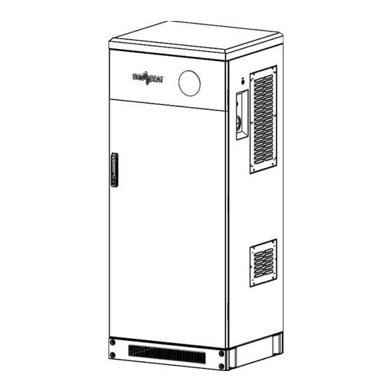
2.2 Structure and Composition The product adopts a modular design framework. The battery box, energy storage inverter and power distribution box are installed in the form of components for easy replacement. (10) (11) (12) (13) Picture 2-2 Product appearance Cabinet top cover Cabinet base LAMP button PCS air inlet... - Page 6 Picture 2-4 Appearance of the inverter DC Switch LCD display Power on/off button Function Buttons Inverter Indicators WiFi Interface Picture 2-5 Appearance of the battery box Mounting holes Button Input and output negative Status Display RS485 Input and output positive CAN Bus (10) Grounding hole...
-
Page 7: Product Installation
Before installation, please check whether the appearance of the machine is intact, and check whether the parts of the accessory package are consistent with the list. Picture Material Name Specification Model QTY. SunBeat 5010A/ SunBeat 8015A/ Energy storage system SunBeat 8020A Energy storage system M12X80 Carbon steel white zinc Expansion screw... - Page 8 Picture Material Name Specification Model QTY. Internet Cable Category 5 network cable 2 meters Cable tie YJ-120 2.5*120mm Nylon; white AC Terminals E10-12 Black PV Terminals E6012 Black Terminals RNYD5-6 Yellow Roll, nylon, black Winding tube 10 General certificate General certificate User Manual English language Drier...
-
Page 9: Installation
3.3 Installation 3.3.1 Installation Preparation The cabinet is installed against the wall and the height of the installation base is greater than 200mm; keep both sides well ventilated, and the minimum gap between the two sides and the top should not be less than Cabinet 3-1. >300mm >500mm >500mm... - Page 10 According to the dimension drawing of the base hole, use a hammer drill to drill holes at the hole location. The diameter of the hole is 14mm and the depth is about 80mm. Knock the expansion bolt into the hole. Remove the front and rear covers of the base.
-
Page 11: Cable Connection
Model Wire Size/Requirements Cable (mm2 ) 8AWG SunBeat 5010A/ SunBeat Yellow-green two-color cable M6 8015A/ SunBeat 8020A Ring terminal Connect one end of the ring terminal of the grounding wire to the grounding point on the top of the cabinet, and the other end to the common grounding point. -
Page 12: Ac Input/Output
Cable (mm2 ) SunBeat 5010A 10AWG SunBeat 8015A/ SunBeat 8020A 8AWG Follow the steps below to complete the AC input/output cable connection: Strip the insulation layer of the cable with a length of 8mm, put on the terminal, and then crimp the cable with a crimping tool. -
Page 13: Pv Connection
The recommended wire specifications for AC input/output are as follows. Model Wire Size Cable (mm2 ) SunBeat 5010A/ SunBeat 8015A/ 12AWG SunBeat 8020A To avoid any malfunction, do not connect any PV modules with possible current leakage to the inverter. For example, grounded PV modules will cause current leakage to the inverter. When using PV modules, please be sure NO grounding. -
Page 14: Ct Connection
Figure 3-10 PV input connection 3.4.5 CT Connection Picture 3-11 CT connection... -
Page 15: Operation Guide
4. Operation Guide 4.1 Battery DIP Switch Setting There is no need to set the dialing address for the battery. The system is already set at the factory. Note: 1. The battery with the address set to 0000 is the host, and it is connected to the inverter through RS485. 2. -
Page 16: Operating Instructions
Dip switch setting table: DIP switch setting position Explain Signal 1# Battery Module 2# Battery Module 3# Battery Module 4# Battery Module 5# Battery Module 6# Battery Module 7# Battery Module 8# Battery Module 4.2 Operating Instructions 4.2.1 System Power Turn on Open the front door of the system, press the POWER button, the battery indicator lights, and the battery is turned on. - Page 17 Close the "GRID" circuit breaker Close the "LOAD" circuit breaker. Push the interlock device toward the Bypass switch and tighten it clockwise; then push the Load switch handle upwards. The "Bypass" switch is only used for inverter maintenance, and this switch is not used by default. Before closing the "Bypass"...
-
Page 18: System Power Off
4.2.2 System Power Off Cut down the circuit breaker. Cut down the circuit breaker Cut down the circuit breaker. Cut down the circuit breaker. Press the battery POWER button, the button pops up, the battery indicator goes out Set the inverter DC switch to "OFF" and press the ON/OFF switch to complete the system shutdown. -
Page 19: Lcd Display Icons
4.3 LCD Display Icons The operation and display panel, shown in below chart, is on the front panel of the inverter. It includes four indicators, four function keys and a LCD display, indicating the operating status and input/output power information. LED Indicator Messages Green led solid light... -
Page 20: Lcd Operation Flow Chart
to red so system info showing vividly on the main screen. PV power and Load power always keep positive. Grid power negative means sell to grid; positive means get from grid. Battery power negative means charge, positive means discharge. 4.3.2 LCD Operation Flow Chart... - Page 21 4.3.3 Solar Power Curve This is Solar Panel detail page. Solar Panel Generation. Voltage, Current, Power for each MPPT. Solar Panel energy for Day and Total. curve page. This is Inverter detail page. Inverter Generation. Voltage, Current, Power for each Phase. DC-T: mean DC-DC temperature, AC-T: mean Heat-sink temperature.
-
Page 22: Curve Page-Solar & Load & Grid
This is Battery detail page. If you use Lithium Battery, you can enter BMS page. 4.3.4 Curve Page-Solar & Load & Grid Solar power curve for daily, monthly, yearly and total can be roughly checked on the LCD, for more accuracy power generation, please check on the monitoring system. -
Page 23: System Setup Menu
4.3.5 System Setup Menu This is System Setup page. 4.3.6 Basic Setup Menu This is Basic Setup page. 4.3.7 Battery Setup Menu Lithium Battery Batt Mode-------- Lithium Max A charge-------- 0-185A Max A Discharge-----0-185A Activate Battery------Enable AGM Battery Batt Mode-------- Lithium Batt Capacity-------- 50-2000Ah No Batt --- No need to set other parameters, keep the default value. - Page 24 This is Grid Charge, you need select. Start =30%---no use, for customization. A =40A---It indicates the Current that the Grid charges the Battery. Grid Charge---The Switch that the Grid charges the Battery. Grid Signal---Disable. Lithium Mode--This is BMS protocol. Shutdown 10%--It indicates the inverter will shut down if the SOC below this value.
-
Page 25: System Work Mode Setup Menu
4.3.8 System Work Mode Setup Menu Work Mode Selling First: It means that the excess energy has priority in grid connection. Zero Export To Load: It means output power according to it consumed by the load. Zero Export To CT: It means output power according to the CT position. -
Page 26: Device Info Setup Menu
UL1741&IEEE1547 CPUC RULE21 SRD-UL-1741: No need to set the function of this interface. General Standard: Please select the correct Grid Frequency in your local area. You can hold this in default value 4.3.10 Device Info Setup Menu This page show Inverter ID, Inverter version and alarm codes. - Page 27 The function description corresponding to the indicator status is shown in the following table: Battery status SOC LED (low to high) Description Power Off LED1 LED2 LED3 LED4 LED5 LED6 All lights are off LED ( 1^4) from up to 0%-25% SOC down for the status of the water lamp...
- Page 28 Low temperature protection High temperature protection MOS tube high temperature protection Charging short circuit protection Short circuit protection Pre-discharge failure Charging MOS failure Discharge MOS failure Voltage front end sampling failure Voltage front end disconnection failure Temperature front end sampling failure Errors The battery is &...
-
Page 29: Display Status
4.5 Display status After the equipment is running normally, the screen will show the corresponding status, and the display status is described in the following table. Status Description When power on, the software version number is displayed, including the main control software version and the display software version. - Page 30 The error codes of the display are described in the following table. Error code Item Troubleshooting Press the battery power button on the power distribution box, and then press the power button Battery overvoltage again after battery completely shut down to restart Error 01 protection the battery.
-
Page 31: Maintenance And Troubleshooting
5. Maintenance and troubleshooting 5.1 Daily Maintenance Calculate from the factory, the system needs to be charged once every 6 months. When the device is not used for a long time, discharge the battery to between 45% and 60% of the battery capacity, and disconnect the battery output to avoid the battery power being emptied. -
Page 32: Inverter Troubleshooting
Failures Reasons Solving methods The inverter is powered on by the battery for the first Inverter battery side input terminal Battery protection can be restored time, the battery reports parallel capacitance value is larger automatically discharge short circuit protection Battery voltage is too low or SOC is After starting the inverter through the grid, The inverter cannot start lower than shutdown protection... - Page 33 Error code Description Solutions Leakage current fault 1.Check the cable of PV module and inverter; AC leakage current is transient over Restart inverter; current Seek help from us, if cannot go back to normal state. PV isolation resistance is too low Check the connection of PV panels and inverter is firmly and correctly;...
-
Page 34: Packaging, Transportation, Storage
ARC fault detection is only for US market; Check PV module cable connection and clear the ARC fault fault; Seek help from us, if cannot go back to normal state. Heat sink temperature is too high Check whether the work environment temperature is too high;... -
Page 35: Appendix A Technical Parameter Table
Appendix A Technical Parameter Table Description SunBeat 5010A SunBeat 8015A SunBeat 8020A Battery Type of battery System capacity 200Ah 300Ah 400Ah Parallel number Rated voltage Voltage Range 51.5V Maximum continuous 100A 150A 150A charging current Maximum continuous 120A 180A 190A... - Page 36 Appendix A Technical Parameter Table Description SunBeat 5010A SunBeat 8015A SunBeat 8020A AC output Output frequency 60Hz Power factor 0.8 leading to 0.8 lagging Current harmonics THD<3% Certifications and Standards Inverter UL1741,IEEE1547, IEC62109-1,IEC62109-2, FCC Class B Battery UN38.3,UL1973 General Data...
Need help?
Do you have a question about the 5010A and is the answer not in the manual?
Questions and answers