Advertisement
Quick Links
Advertisement

Related Manuals for Glide 6 Series


Summary of Contents for Glide 6 Series
- Page 1 REHABILITATION PRODUCTS SERIES 6 & 7 OWNER/USER MANUAL For your safety and comfort read carefully and understand all of the features prior to using your new Glide Power Chair. Misuse may result in electrical or mechanical damage Maximum Recommended User Weight 175kg...
- Page 2 SECTION 1. INTRODUCTION SECTION 2. STANDARD FEATURES SECTION 3. WARNINGS SECTION 4. TRANSPORTING THE POWER CHAIR SECTION 4. OPERATING YOUR WHEELCHAIR SECTION 5. BATTERY CHARGING AND MAINTENANCE SECTION 6. ROUTINE MAINTENANCE SECTION 7. TROUBLE SHOOTING SECTION 8. PENNY & GILES PILOT SERIES POWER CHAIR CONTROLLER SECTION 9.
-
Page 3: Section 1. Introducton
SECTION 1. INTRODUCTON Thank you for choosing the Glide Power Wheelchair. An Australian designed and manufactured product, which complies with AS 3695 and has a manufacturers recommended maximum user weight of 175kg. With proper care and operation your wheelchair will provide years of trouble free mobility. -
Page 4: Section 2. Standard Features
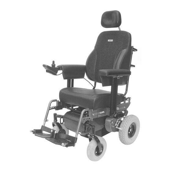
The illustration (Fig 1. below) is a list of the Series 6 & Series 7 standard features Drop Down Arms Battery Pack Drive Clutch Front Castor Wheels Controller “CTA”Suspension Footrests Fold Down Back Attendant Brakes 10. Legrest release lever FIGURE 1. STANDARD FEATURES... -
Page 5: Section 3. Warnings
The Glide Rehabilitation Products Power Chair has been designed and tested with user safety, as it’s prime consideration. The “CTA Suspension System” has been designed to automatically adjust to uneven surfaces and changes in height, allowing all four wheels to stay in contact with the ground under most conditions. - Page 6 Even though the “CTA System” improves manoeuvrability and stability, this does not negate the effect or take into account, circumstances, which put the wheelchair outside the specified operating conditions for which it was designed and tested. It is important that the user takes due care and understands the limitations within the environment that the chair will be operated.
- Page 7 Drive chair at a slow steady speed .Do not allow chair to accelerate over • normal speed. Centre the joystick to allow it to slow down or stop. Never use attendant brakes to slow or stop the chair. This may cause the chair •...
- Page 8 MODIFICATIONS WARNING! Never make any modifications or use non-approved Glide Rehabilitation Products parts on your power chair. Doing so may cause a safety hazard and could void Warranty. Unauthorised changes constitute remanufacturing of the power chair. This voids any warranty. The person or group who make the changes will have full liability of the power chair.
-
Page 9: Section 4. Operating Your Power Chair
SECTION 4. OPERATING YOUR POWER CHAIR CONTROLLER Your new Power Chair has the option of two types of control systems, Dynamic Controls or Penny & Giles Controls. You will have been given instruction on how to operate your controller at time of specification. WARNING: Never push the On /Off button or pad on the control box until you are seated correctly in the chair and have your hand on the control box. -
Page 10: Drive Clutch
Clamp Type – to adjust height simply loosen clamp bolt, move to desired position, retighten clamp bolt. Incremental Hole Type – to adjust height simply un - do and remove bolt, move footplate to nearest hole to suit desired height, replace and tighten bolt firmly. -
Page 11: Section 5. Transporting Your Power Chair
SECTION 5. TRANSPORTING YOUR POWER CHAIR Transporting your Power Chair in motor vehicles can be easily achieved by the following methods STATION WAGON The backrest folds down onto the seat by pulling out pins A, B, and C (see Fig 2 below) Note: Pins A &... - Page 12 FIGURE 2. FOLD DOWN BACKREST...
-
Page 13: Section 6. Battery Charging And Maintenance
SECTION 6. BATTERY CHARGING AND MAINTENANCE Keeping the Power Chair working to its maximum potential it is recommended the batteries be charged every night. This will ensure a longer life for the batteries and chair will be ready to go when you are. Your Power Chair battery charger is special to your chair and may not be suitable for other power chairs. -
Page 14: Section 7. Routine Maintenance
SECTION 7. ROUTINE MAINTENANCE DAILY Charge your batteries every night so your Power Chair is ready to go when you are. WEEKLY Check tyre pressures (30PSI front, 30PSI rear) Clean frame and vinyl parts with mild soapy solution. Wipe upholstery with a clean damp cloth Check function of electric brakes Check all cables and connectors are secured;... -
Page 15: Section 8. Trouble Shooting
SECTION 8. TROUBLE SHOOTING If your Power Chair will not go, follow this checklist Check that the lights on control box are illuminated. If there are no lights on controller, check that all leads/plugs, which connect to controller, are pushed in properly. Check that the motor cables are properly connected Check all battery wiring is connected. -
Page 16: Section 9. Penny & Giles Pilot + Series Controller
SECTION 9. PENNY & GILES PILOT + SERIES CONTROLLER Figure 3. Penny & Giles Controller... - Page 17 CONTROLS On/Off Push button This is a green pushbutton switch fitted in front of the joystick, which turns the controller On and Off. Do not use this switch to stop the wheelchair except in an emergency. TruCharge Battery Gauge This is a 10 segment illuminated display which indicates if the controller is turned On and also gives the status of the battery, the controller and the wheelchair electrical system.
- Page 18 To adjust speed when in this mode – The maximum speed can be adjusted by left or right movements of the joystick. Left will decrease the speed, right will increase it. Forward or reverse movements of the joystick will take you back into drive mode.
-
Page 19: Section 10. Dynamic Controls Controller
SECTION 10. DYNAMIC CONTROLS CONTROLLER Figure 5. Dynamic Controller... - Page 20 CONTROLS DX – G90A REMOTES On/Off Button – This is a white pad located in front of joystick control knob. It is also identified by having 1/0 printed on it. Mode/Program Select Button This is a Light Blue pad located to the left of the On/Off pad. Each press of the mode button will increment the drive profile, up to the maximum configured value, and then back to profile 1.
- Page 21 Figure 6. Dynamic Control Panel...
- Page 22 Dynamic Shark Controller Models DK – REMA - No Seat Functions DK – REMB – Two Seat Functions Controls All user controls can be accessed from the simple, ergonomically designed panel on the Shark Control Unit DK – REMB shown...
- Page 23 The Shark Information Gauge The Shark information gauge is the primary source of user feedback. It displays every possible status that SHARK may have, including; Shark Power On • True state of battery charge, including notification of when the battery •...
- Page 24 Turning the SHARK On and OFF Turning the Power ON Press the Power Button • All indicators will light briefly • Either the current battery charge or Lock Mode will then be indicated • Turning the Power OFF Press the Power button •...
- Page 25 Sleep Mode Some Sharks may be supplied factory programmed with a Sleep feature that will automatically turn SHARK off if the joystick has not been moved within a certain period of time. Sleep mode will not be entered while programming. When Wakeup style has been set to ‘Joystick and Buttons’, pressing ANY button or displacing the joystick will bring the system out of Sleep mode.
- Page 26 Note: User should ensure proper mode is selected before attempting to drive or operate actuator. Locking the SHARK Some SHARKS may be supplied factory programmed with a LOCK feature that prevents unauthorised people from turning SHARK on. To LOCK Shark While the power is ON, press and hold the POWER button for 2 seconds •...
- Page 27 Note: If the user does not press the horn button twice before the countdown is complete, the HORN will sound a short BEEP and Shark will turn itself off. The sequence must be completed successfully before SHARK will drive again normally. Charging SHARK Plug the battery charger into the charging socket at the front of the SHARK Control unit If the powerchair has an On-board Battery charger (OBC), simply plug the OBC power...
-
Page 28: Section 11. Precautions For Controller Use
SECTION 11. PRECAUTIONS FOR CONTROLLER USE The Dynamic and Penny & Giles controller has been designed with the user safety as the prime consideration. They incorporate many, sophisticated self – test features which search for potential problems. If the controller detects a problem either in its own circuits, or in the wheelchairs electrical system, it may decide to halt the wheelchair depending on the severity of the fault. -
Page 29: Section 12. Transferring To And From Your Power Chair
SECTION 12. TRANSFERRING TO AND FROM YOUR POWER CHAIR. The Glide Rehabilitation Products Power Chair is designed in such a way that transferring in and out can be done with a minimum of fuss. Armrests can either be dropped down or flipped back (depending on type specified when ordering) allowing easy lateral movement from either side of chair or for the fitting of a patient hoist sling. -
Page 30: Section 13. Battery Wiring Diagram
SECTION 13. BATTERY WIRING DIAGRAM 2 x 36Amp Hour Sealed Deep Cycle Batteries Consult your Glide Products agent when replacement is required. -
Page 31: Section 14. Spare Parts
TYRES 8” Pneumatic Front (200 x 50) 9” Pneumatic Front (2.80/2.50) 10” Pneumatic Front (260 x 85) 12 ½ x 2 ¼ Wheel (Narrow) 4.10/3.50 – 6 Wheel (Wide) TUBES 8” Front 9” Front 10” Front 4.10/3.50 – 6 Wheel 12 ½... -
Page 32: Section 15. Warranty
Lendal Pty Ltd (trading as Glide Rehabilitation Products) warrants the following as listed: Controllers 12-months warranty Controllers and associated hardware will be repaired where possible. Replacement will only occur if repair is not practical or not possible. Motors/Gearbox 12-months Automatic replacement within six months of invoice. There afterwards, unit must be returned for evaluation and possible repair before replacement Actuators 12 months warranty. - Page 33 Lendal Pty Ltd (trading as Glide Rehabilitation Products) does not warrant either expressly or impliedly the suitability of the Glide Series 8 electric wheelchair for the purchaser or any intended user. Purchasers and intended users are advised that advice from an appropriate registered medical practitioner should be obtained prior to using an electric wheelchair.
Need help?
Do you have a question about the 6 Series and is the answer not in the manual?
Questions and answers