Table of Contents
Advertisement
Quick Links
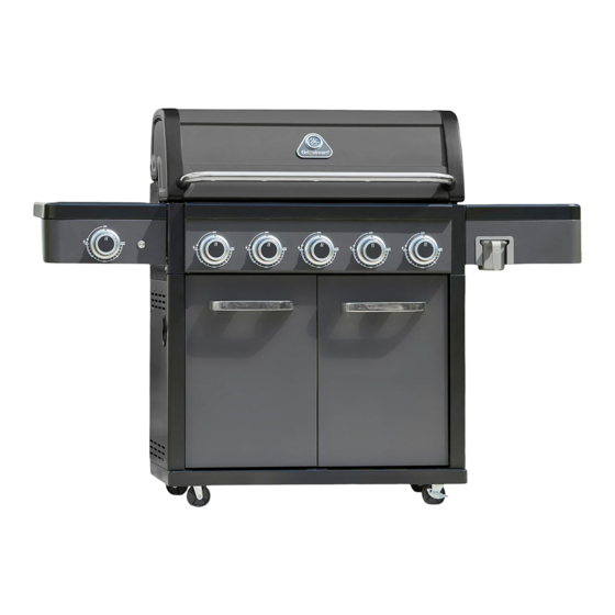
Legacy 5 Burner Hybrid Barbecue
x 44
WARNING! FOR YOUR SAFETY, FOR OUTDOOR USE ONLY
Please read these instructions carefully and ensure that your barbecue is properly installed, assembled,
maintained and serviced in accordance with these instructions.
Failure to follow these instructions may result in serious injury and/or damage to property.
Necessary
Tools
Please check the pack contents before attempting to assemble this product. A full checklist of
components is given in this leaflet. If any components are missing, please contact the retailer from
whom you bought this product.
This product takes approximately 120 MINUTES
to assemble with 2 PEOPLE. The fittings pack
contains SMALL ITEMS which should be KEPT
AWAY FROM YOUNG CHILDREN. Read this
leaflet in full before commencing assembly.
GLH55MK
x 4
x 12
x 12
x 2
x 44
AA Battery (Not included)
Carbon Monoxide Hazard
Using a barbecue inside can kill you,
it gives off Carbon Monoxide, which has no odour.
Never use a barbecue in enclosed spaces such as
a tent, home/building, vehicle or garage.
Advertisement
Table of Contents

Related Manuals for Grillstream Legacy GLH55MK


Summary of Contents for Grillstream Legacy GLH55MK
- Page 1 Legacy 5 Burner Hybrid Barbecue GLH55MK x 44 x 12 x 44 x 12 WARNING! FOR YOUR SAFETY, FOR OUTDOOR USE ONLY Please read these instructions carefully and ensure that your barbecue is properly installed, assembled, maintained and serviced in accordance with these instructions. Failure to follow these instructions may result in serious injury and/or damage to property.
-
Page 2: Table Of Contents
GLH55MK Contents Warning Information Page Location of your BBQ Page Connecting to the gas cylinder Page The hose and regulator assembly Page Testing for leaks Page Gas cylinder safety Page What is Propane Page Are all gas bottle gases the same Page How is it different from natural gas Page... -
Page 3: Warning Information
IMPORTANT - BBQS MUST BE INSTALLED IN ACCORDANCE WITH THE MANUFACTURER’S INSTALLATION INSTRUCTIONS, LOCAL GAS FITTING REGULATIONS AND MUNICIPAL BUILDING CODES. GRILLSTREAM BARBECUES, Think carefully when deciding on a location where you are to use your LEISUREGROW PRODUCTS LTD. 8504-23 2531-23 BBQ. -
Page 4: Testing For Leaks
GLH55MK SECURING THE HOSE AND REGULATOR ASSEMBLY GAS CYLINDER SAFETY Quick release connection (Fig. 4) - Always change over a gas cylinder away from any possible source - The BBQ’s manifold connection is a quick release connector of ignition in a well ventilated area - Gently pull back the movable section on the hose, slide over the - Do not smoke whilst handling gas cylinders connection on the manifold, and release. -
Page 5: Lighting Your Bbq
• OFF position and wait five minutes for any accumulated gas to clearout of the BBQ before repeating procedure. CONTROLLING YOUR BBQ (GAS-MODE) Grillstream Grills fit directly on top of each other - do not offset them. lo position is obtained by turning the knob fully anti-clockwise - The... -
Page 6: Hybrid System
DIRECTIONS FOR USE - GAS: single layer, stood up on end (as illustrated) to allow optimal loading. The beauty of the Grillstream Hybrid System is that there is no Place your Grillstream Grills back into position. It is important that additional assembly or conversion process required, whether you want the Charcoal Trays are not overloaded with charcoal –... -
Page 7: Maintenance Of Your Bbq
To clean the Grills effectively use the Grillstream cleaning brush which has been specially designed to quickly and effectively clean your Grillstream Grills. Rinse off with clean water and dry before returning to BBQ. -
Page 8: Troubleshooting
- Empty the fat cup responsibly after each use. burners over orifices and test again WARRANTY All of our Grillstream BBQs and accessories are built to last. Our materials are carefully considered with longevity and safety in mind, the technology used in our products is second to none, and all of this is backed up with our friendly customer care team who are on hand for advice and assistance. -
Page 9: Exploded Diagram
GLH55MK Page 9... -
Page 10: Parts List
Side Shelf Brace - Left Flame Tamer Side Burner Lid Hybrid Flame Tamer Side Burner Support Drip Pan Fat Channel Side Burner Lid Grillstream Grill Side Burner Trivet Cleaning Tool Side Shelf - Right Warming Rack Side Shelf Fascia - Right Match Holder... -
Page 11: Fittings List
GLH55MK FITTINGS Part Part Part Part 1/4” x 38 Bolt 1/4” x 16 Bolt No.10 x 13 Bolt No.8 x 9.5 Countersunk Bolt Part Part Part Part Self Tapping φ7 Fiber washer 1/4” Nut LED Bezel Screw x 44 Part Part Part Part... - Page 12 GLH55MK STEP 1 Line up the two sets of holes in Castor (EH) and insert Castor Pin. Screw Castor into holes on underside of Cabinet Base Panel (EF) then remove Castor Pin. Repeat for other Castor and Lockable Castors (EG) Part Castor Pin Page 12...
- Page 13 GLH55MK STEP 2 Attach Cabinet Side Panel - Left (EA) to Cabinet Base Panel (EF) using 4 x Bolt (2). Repeat for Cabinet Side Panel - Right (EB). Part 1/4” x 16 Bolt Page 13...
- Page 14 GLH55MK STEP 3 Attach Cabinet Lower Rear Panel (CN) to Cabinet Side Panels (EA & EB) using 4 x Bolt (2). Part 1/4” x 16 Bolt Page 14...
- Page 15 GLH55MK STEP 4 Attach Front Support Bar (CJ) to Cabinet Side Panels (EA & EB) using 4 x Bolt (2). Note the lip and magnets should be at the top. Part 1/4” x 16 Bolt Page 15...
- Page 16 GLH55MK STEP 5 Insert Grease Cup Rail (CL) into underside of Grease Tray (CO) and secure in place using 2 x Self Tapping Screw (5). Repeat for second Grease Cup Rail. Part Self Tapping Screw Page 16...
- Page 17 GLH55MK STEP 6 Attach Grease Tray (CO) to Cabinet Side Panels (EA & EB) using 4 x Self Tapping Screw (5). Then slide Grease Cup (CK) onto Grease Rails through hole located in in Cabinet Side Panel - Left. Part Self Tapping Screw Page 17...
- Page 18 GLH55MK STEP 7 Carefully lower Cooking Frame (BA) onto Cabinet, ensuring any hoses and wires are not trapped. Secure in place using 4 x Bolt (2) Part 1/4” x 16 Bolt WARNING: WATCH YOUR HANDS! Page 18...
- Page 19 GLH55MK STEP 8 Secure Cabinet Upper Rear Panel (EB) onto Cooking Frame (BA) using 2 x Bolt (1) and 2 x Washer (6). Now secure onto Cabinet Side Panels using 2 x Bolt (1). Part Part 1/4” x 38 Bolt φ7 Fiber washer Page 19...
- Page 20 GLH55MK STEP 9 Attach Side Shelf Brace - Left (DC) to underside of rear of Side Burner Side Shelf (DA) using 2 x Bolt (3). Now attach Side Shelf Fascia - Left (DB) to underside of rear of Side Burner Side Shelf (DA) using 3 x Bolt (3).
- Page 21 GLH55MK STEP 10 Slide tabs of Side Burner Side Shelf (DA) through slots in Cooking Frame (BA) to help support it while you secure it in place. Now further secure from inside the Cooking Frame using 3 x Bolt (2) and 3 x Washer (6).
- Page 22 GLH55MK STEP 11 Secure Side Shelf Brace - Left (DC) into Cooking Frame using 1 x Bolt (1), 1 x Washer (6) and 1 x Nut (7). Next, secure Side Shelf Fascia - Left (DB) into Cooking Frame using 2 x Bolt (3). Part Part Part...
- Page 23 GLH55MK STEP 12 Unscrew nut from LED Light Switch (CE) and insert into Side Shelf Fascia – Left (DB) as indicated. Thread nut back in place to secure LED Light Switch. Now locate the LED Light Wire and attach it to the rear of LED Light Switch.
- Page 24 GLH55MK STEP 13 Move Side Burner Valve (CC) into place behind Side Shelf Fascia - Left, pushing Control Spindle through the hole located in the fascia. Locate the LED Control Knob Wire and push connector through hole located in fascia, and then into socket on back of LED Bezel (8) and secure Bezel and Valve in place using 2 x Bolt (13).
- Page 25 GLH55MK STEP 14 Lift lid on Side Burner Side Shelf and insert Side Burner. Secure in place using Wing Nut (10) and Side Burner Valve Clip (11). Part Part No.8 Wing Nut Sideburner Valve Clip NOTE: Push the LED socket in Firmly. Page 25...
- Page 26 GLH55MK STEP 15 With Side Burner Side Shelf lid still up, place Side Burner Trivet (DH) above Side Burner. Page 26...
- Page 27 GLH55MK STEP 16 Attach Side Shelf Brace - Right (DK) to underside of rear of Side Shelf - Right (DI) using 2 x Bolt (3). Now attach Side Shelf Fascia - Right (DJ) to underside of rear of Side Shelf - Right using 3 x Bolt (3). Part No.10 x 13 Bolt Page 27...
- Page 28 GLH55MK STEP 17 Slide tabs of Side Shelf (DI) through slots in Cooking Frame (BA) to help support it while you secure it in place. Secure from inside the Cooking Frame using 3 x Bolt (2) and 3 x Washer (6). Next, secure Side Shelf Brace - Right (DK) into Cooking Frame using 1 x Bolt (1), 1 x Washer (6) and 1 x Nut (7).
- Page 29 GLH55MK STEP 18 Insert Fat Cup Holder (DL) into Side Shelf Fascia - Right and secure in place using 3 x Countersunk Bolt (4). Now insert Fat Cup (DM) into Fat Cup Holder. Part No.8 x 9.5 Countersunk Bolt Page 29...
- Page 30 GLH55MK STEP 19 Secure Battery Box (CQ) and Battery Box Heat Shield (CP) in place using 2 x Self Tapping Screw (5). Now insert 4 x AA batteries (not supplied) ensuring correct polarity on each. Finally locate and connect LED Light wire to terminal on Battery Box. Part Self Tapping Screw...
- Page 31 GLH55MK STEP 20 Connect quick release hose to terminal on Side Burner by pushing firmly. To disconnect, pull back the movable section on hose and pull apart. Please ensure you perform a gas leak check on this connection as instructed at the end of this manual. Page 31...
- Page 32 GLH55MK STEP 21 Insert 2 x Door Handle Spacer (EJ) into reverse of Cabinet Door - Left (EC). Now attach Door Handle (EE) to front of Cabinet Door - Left using 2 x Bolt (3). Repeat for Cabinet Door - Right (ED). Part No.10 x 13 Bolt Page 32...
- Page 33 GLH55MK STEP 22 Insert spindle located at bottom of Cabinet Door - Left (EC) into hole on Cabinet Base Panel. Depress spring-loaded catch located at top of Cabinet Door - Left and move into place until spring-loaded catch extends into hole located on underside of Cooking Frame. Repeat for Cabinet Door - Right (ED).
- Page 34 GLH55MK STEP 23 Lift Hood and insert Hybrid Flame Tamers (BE) and Flame Tamer (BD). Both types of Flame Tamer should sit directly above the burner tubes. Page 34...
- Page 35 GLH55MK STEP 24 Insert Fat Channel (BF) into Cooking Frame by first sliding the thin end (spout) through right-hand side of Cooking Frame and then slotting the front lip of the Fat Channel between and Cooking Frame and Control Panel. Page 35...
- Page 36 GLH55MK STEP 25 Place Grillstream Grills (BG) Griddle Plate (BK) into Cooking Frame. Leg tabs from both types of Grill should rest on lip at back of Cooking Frame. Top Grills should sit directly on top of the bottom Grill.
- Page 37 GLH55MK STEP 26 Insert Warming Rack (BI) into place, ensuring leg tabs at the back slot into holes located in the rear of the Cooking Frame. Page 37...
-
Page 38: Leak Test
GLH55MK TESTING YOUR BBQ TESTING FOR LEAKS - DO THIS BEFORE USING YOUR BBQ. Note - Do not test for gas leaks with an open flame. If you smell gas, turn off at the source. Before first use, at the beginning of each new season, or whenever a gas cylinder is changed, you must check for gas leaks. - Page 39 GLH55MK Page 39...
- Page 40 GLH55MK PLEASE KEEP THESE INSTRUCTIONS FOR FUTURE REFERENCE Grillstream Barbecues Part of the LeisureGrow Group Dewmead Farm, New Inn Road, Hinxworth, Hertfordshire SG7 5HG, United Kingdom. Tel: +44 (0)1462 744500 Page 40 E-mail:salessupport@leisuregrow.com...
Need help?
Do you have a question about the Legacy GLH55MK and is the answer not in the manual?
Questions and answers