Table of Contents
Advertisement
Quick Links
Advertisement
Table of Contents

Related Manuals for Vertiv UL891


Summary of Contents for Vertiv UL891
- Page 1 UL891 Switchboard Installer/User Guide...
- Page 2 The products covered by this instruction manual are manufactured and/or sold by Vertiv. This document is the property of Vertiv and contains confidential and proprietary information owned by Vertiv. Any copying, use, or disclosure of it without the written permission of Vertiv is strictly prohibited.
-
Page 3: Table Of Contents
4.6.3 Cable Connections 4.6.4 Busway 5 Energization 5.1 Pre-Energization 5.1.1 Pre-Energization Tests 6 Maintenance 6.1 Setting Up a Maintenance Schedule 6.2 Maintenance Inspections 7 Torque Table 8 Accessories 8.1 OHLD Installation 8.2 OHLD Operation Proprietary and Confidential ©2024 Vertiv Group Corp. - Page 4 Vertiv™ UL891 Switchboard Installer/User Guide Appendices Appendix A: Technical Support and Contacts Appendix B: Submittal Drawings Proprietary and Confidential ©2024 Vertiv Group Corp.
-
Page 5: Important Safety Instructions
All models represented in this manual are for illustrative purposes only, due to the individual specifications associated with each customer. Vertiv will not assume responsibility for actual use establish by the models. - Page 6 Vertiv™ UL891 Switchboard Installer/User Guide This page intentionally left blank Proprietary and Confidential ©2024 Vertiv Group Corp. 1 Important Safety Instructions...
-
Page 7: Introduction
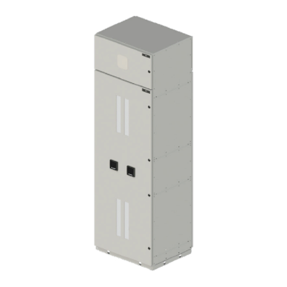
Safe and Reliable Built and tested with IEC influence, the design of our UL891 Switchboard is focused on achieving the highest standard of performance reliability and operator safety. Internal segregation as outlined by IEC 61439-2 reduces operator risk by limiting the propagation of internal arc fault and preserves uptime during maintenance and upgrade operations. - Page 8 Vertiv™ UL891 Switchboard Installer/User Guide Figure 2.1 Typical Switchboard Figure 2.2 Typical Power Distribution Unit (PDU) Figure 2.3 Typical Remote Power Panel (RPP) Proprietary and Confidential ©2024 Vertiv Group Corp. 2 Introduction...
-
Page 9: Design Features And Components
PDUs and RPPs use the same typical layouts, but use different components to achieve their designated goal, such as transformers and panelboards. Figure 2.4 Rear Internal View Figure 2.5 Front Internal View 2 Introduction Proprietary and Confidential ©2024 Vertiv Group Corp. -
Page 10: Typical Switchboard Layouts
MCCB’s use rotary handles for turning the breakers on and off. In a front access only switchboard, there is a cableway for field termination. Figure 2.6 Typical ACB Layout Front Access - Single ACB Front Access -Double ACB Rear Access - Single ACB Rear Access - Double ACB Proprietary and Confidential ©2024 Vertiv Group Corp. 2 Introduction... -
Page 11: Typical Customer Connections
All lug pads consist of the standard NEMA hole pattern, which is 1.75 in. x 1.75 in. with a clearance hole for 0.5 in. hardware. The 0.5 in. hardware consists of a bolt, 2 Belleville washers (one on each side of the connection), and a nut. 2 Introduction Proprietary and Confidential ©2024 Vertiv Group Corp. - Page 12 Figure 2.8 Typical Provision for Front Access and Top Incoming Customer Cable Connections Figure 2.9 Typical Provision for Front Access and Bottom Incoming Customer Cable Connections Figure 2.10 Typical Provision for Rear Access and Top Incoming Customer Cable Connections Proprietary and Confidential ©2024 Vertiv Group Corp. 2 Introduction...
- Page 13 Vertiv™ UL891 Switchboard Installer/User Guide Figure 2.11 Typical Provision for Rear Access and Bottom Incoming Customer Cable Connections Figure 2.12 Typical Provision for Rear Access and Bottom Incoming Customer Cable Connections 2 Introduction Proprietary and Confidential ©2024 Vertiv Group Corp.
-
Page 14: Typical Ground Layout
Below are typical arrangements of ground cable provisions per switchboard configuration. Figure 2.15 Typical Ground Dropper Arrangement with Provisions for up to two (2) Compression Lugs Proprietary and Confidential ©2024 Vertiv Group Corp. 2 Introduction... - Page 15 Figure 2.16 Alternate Ground Dropper Arrangement with Provisions for up to two (2) Compression Lugs Figure 2.17 Typical Ground Dropper Arrangement with Provisions for up to four (4) Compression Lugs Figure 2.18 Alternate Ground Dropper Arrangement with Provisions for up to four (4) Compression Lugs 2 Introduction Proprietary and Confidential ©2024 Vertiv Group Corp.
-
Page 16: Technical Information
Vertiv™ UL891 Switchboard Installer/User Guide 2.7 Technical Information Table 2.1 Technical Information Safety UL891 - Standard for Safety Switchboards Standard Seismic Requirement IBC 2012 and CBC 2010 Seismic Protection AC156 Test Switchboard is designed, tested, and constructed based on the... - Page 17 Vertiv™ UL891 Switchboard Installer/User Guide Figure 2.19 Typical Labels 2 Introduction Proprietary and Confidential ©2024 Vertiv Group Corp.
- Page 18 Vertiv™ UL891 Switchboard Installer/User Guide This page intentionally left blank Proprietary and Confidential ©2024 Vertiv Group Corp. 2 Introduction...
-
Page 19: Packaging And Handling
3.1 Receiving • Ensure all sections and splits are present when switchboard arrives on site. Notify your Vertiv representative if any anomalies are found. • A thorough inspection should be performed to make sure no damages occurred during shipment. If damages did occur, a qualified technician needs to investigate the gear for proper diagnosis. -
Page 20: Unloading Off Pallet
Method 2b on page 17 . NOTE: Vertiv does not provide bars, jacks, skates, straps or spreaders. It is the customers responsibility to purchase or rent the correctly rated equipment needed to move the panel splits. The switchboards also need to be unbolted from the pallet first before lifting the panel. There are holes within the plinth of each panel that allows for a steel bar to go through. - Page 21 3. Remove the bars and then push the panel on the skates to the designated location. 4. Re-insert the bars and raise the split using the jacks then remove the skates and lower the panel onto the ground. 3 Packaging and Handling Proprietary and Confidential ©2024 Vertiv Group Corp.
- Page 22 4. Move the panel to the designated location by the forklift or crane. 5. Lower the panel onto the ground and detach the spreader and lifting straps, as well as the bars. Proprietary and Confidential ©2024 Vertiv Group Corp. 3 Packaging and Handling...
- Page 23 3. Use a forklift or crane to lift the spreader and raise the panel and lower the panel to the minimum moving height. 4. Move the panel to the designated location using a forklift or crane, then lower the panel onto the ground and detach the spreader and lifting straps. 3 Packaging and Handling Proprietary and Confidential ©2024 Vertiv Group Corp.
- Page 24 4. Once the plinths are installed, then panel movements can be completed by a qualified movement team based on specific project MOP. 5. When the panel is in the designated location remove the additional plinths and put back the skin in place. Proprietary and Confidential ©2024 Vertiv Group Corp. 3 Packaging and Handling...
- Page 25 Description M8x12 low profile Skin to be removed Figure 3.8 Installing the Plinth End Item Description M8x16 socket head to mount plinth end to frame Plinth end to install 3 Packaging and Handling Proprietary and Confidential ©2024 Vertiv Group Corp.
-
Page 26: Storage
If the unit is going to be stored for an extended period, the sections and splits should be re-covered in the packaging material or plastic cover to help protect them. Proprietary and Confidential ©2024 Vertiv Group Corp. 3 Packaging and Handling... -
Page 27: Installation
Access is provided to each anchoring location using the large lifting holes in each plinth. After anchoring is complete install supplied plinth caps. Refer to manufacturer drawings for exact location of anchoring holes for your specific panel. 4 Installation Proprietary and Confidential ©2024 Vertiv Group Corp. - Page 28 Vertiv™ UL891 Switchboard Installer/User Guide Figure 4.1 Anchoring Detail Figure 4.2 Typical Anchoring Locations from Edge of Plinth Item Description Anchoring Holes 0.453 Plinth access to anchorage point Proprietary and Confidential ©2024 Vertiv Group Corp. 4 Installation...
-
Page 29: Considerations For Installation
Where two or more type 1A or type 3R switchboard sections come together, they should first be aligned, then all sections leveled. Once aligned and leveled, join the switchboard sections together. 4 Installation Proprietary and Confidential ©2024 Vertiv Group Corp. -
Page 30: Joining Sections
Figure 4.5 Typical Frame Joining Item Description Joining Screw Joining screw threads into both frame Proprietary and Confidential ©2024 Vertiv Group Corp. 4 Installation... - Page 31 (3) separate cluster of joining screw up the height of the front and rear. Only one (1) cluster of joining screw on top for anything less than 30.236 in. two (2) set for anything over 30.236 in. 4 Installation Proprietary and Confidential ©2024 Vertiv Group Corp.
-
Page 32: Transformer Close Coupled Connection
(see Figure 4.8 on the facing page ). The copper from the switchboard and the transformer are typically connected via flexibar or braided copper rated for the application. Both normally connect using 0.5 in. or M12 hardware. Proprietary and Confidential ©2024 Vertiv Group Corp. 4 Installation... -
Page 33: Electrical Connections
Apply torque settings for M10 hardware as set forth in Table 7.1 on page 43 . 4 Installation Proprietary and Confidential ©2024 Vertiv Group Corp. - Page 34 Figure 4.9 Straight Bus Connection – Traditional Fish Plates 800A (2X30X10) Figure 4.10 Straight Bus Connection – Traditional Fish Plates 1200A (2X40X10) Figure 4.11 Straight Bus Connection – Traditional Fish Plates 1600A (2X60X10) Proprietary and Confidential ©2024 Vertiv Group Corp. 4 Installation...
- Page 35 Figure 4.12 Straight Bus Connection – Traditional Fish Plates 2000A (2X80X10) Figure 4.13 Straight Bus Connection – Traditional Fish Plates 2500A (2X100X10) Figure 4.14 Straight Bus Connection – Traditional Fish Plates 2500A (3X80X10) 4 Installation Proprietary and Confidential ©2024 Vertiv Group Corp.
- Page 36 Figure 4.15 Straight Bus Connection – Traditional Fish Plates 3000A (2X100X10) Figure 4.16 Straight Bus Connection – Traditional Fish Plates 3000A (3X80X10) Figure 4.17 Straight Bus Connection – Traditional Fish Plates 4000A (3X100X10) Proprietary and Confidential ©2024 Vertiv Group Corp. 4 Installation...
- Page 37 Figure 4.18 Straight Bus Connection – Splice Fish Plates 2000A (2X80X10) Figure 4.19 Straight Bus Connection – Splice Fish Plates 2500A-3000A (2X100X10) Figure 4.20 Straight Bus Connection – Splice Fish Plates 2500A-3200A (3X80X10) 4 Installation Proprietary and Confidential ©2024 Vertiv Group Corp.
- Page 38 Figure 4.21 Straight Bus Connection – Splice Fish Plates 4000A (3X100X10) Figure 4.22 Transition Bus Connection – Traditional Fish Plates 800A (2X30X10) Figure 4.23 Transition Bus Connection – Traditional Fish Plates 1200A (2X40X10) Proprietary and Confidential ©2024 Vertiv Group Corp. 4 Installation...
- Page 39 Figure 4.24 Transition Bus Connection – Traditional Fish Plates 1600A (2X60X10) Figure 4.25 Transition Bus Connection – Traditional Fish Plates 2000A (2X80X10) Figure 4.26 Transition Bus Connection – Traditional Fish Plates 2500A (2X100X10) 4 Installation Proprietary and Confidential ©2024 Vertiv Group Corp.
- Page 40 Vertiv™ UL891 Switchboard Installer/User Guide Figure 4.27 Transition Bus Connection – Traditional Fish Plates 2500A (3X80X10) Figure 4.28 Transition Bus Connection – Traditional Fish Plates 3000A (2X100X10) Proprietary and Confidential ©2024 Vertiv Group Corp. 4 Installation...
-
Page 41: Ground Bus Connection
(top vs bottom incoming/outgoing, front vs rear access and so on). When joining the ground bus, apply torque settings for M10 hardware as set forth in Table 7.1 on page 43 . 4 Installation Proprietary and Confidential ©2024 Vertiv Group Corp. -
Page 42: Cable Connections
(see Figure 4.32 below ). NOTE: Vertiv not responsible for providing the lugs, but does supply the lug landing pads for mounting. Vertiv will supply standard lug pads for all amperages, custom pads can be supplied on a per project basis. - Page 43 (or rope having a minimum tensile strength of 2000 lbs) at 6 in., and then after every 12 in. see Figure 4.33 below . Figure 4.33 Typical Lashing Details Item Description 5 Wraps as required 5 Wraps 5 Wraps (3X) 10 Perimerter wraps 4 Installation Proprietary and Confidential ©2024 Vertiv Group Corp.
-
Page 44: Busway
The below images illustrate proper installation of an Vertiv panel flange, using M8 hardware. Front, side, and/or rear covers may need to be removed to access hardware on the underside of the gland plate. Apply torque settings for hardware as set forth in Table 7.1 on page 43 . -
Page 45: Energization
2.2 kV Hipot test. Once these tests are complete, the switchboard can be returned to its normal state with all control fuses/circuit breakers installed or closed. The switchboard is now ready for energization. 5 Energization Proprietary and Confidential ©2024 Vertiv Group Corp. - Page 46 Vertiv™ UL891 Switchboard Installer/User Guide This page intentionally left blank Proprietary and Confidential ©2024 Vertiv Group Corp. 5 Energization...
-
Page 47: Maintenance
This includes and is not limited to the low voltage circuit breakers, instruments, indicators, meters, and any other possible components that are installed within the equipment. 6 Maintenance Proprietary and Confidential ©2024 Vertiv Group Corp. - Page 48 Vertiv™ UL891 Switchboard Installer/User Guide This page intentionally left blank Proprietary and Confidential ©2024 Vertiv Group Corp. 6 Maintenance...
-
Page 49: Torque Table
If the hardware is not marked or specified below, then it is understood that hand tight capacity, which on average is 2 ft-lbs (3 Nm), is acceptable. Table 7.1 Torque Values Bolt Size Standard (ft-lbs) Metric (Nm) 0.375 in. 40.5 0.5 in. 7 Torque Table Proprietary and Confidential ©2024 Vertiv Group Corp. - Page 50 Vertiv™ UL891 Switchboard Installer/User Guide This page intentionally left blank Proprietary and Confidential ©2024 Vertiv Group Corp. 7 Torque Table...
-
Page 51: Accessories
Vertiv™ UL891 Switchboard Installer/User Guide 8 Accessories The primary accessory offered by Vertiv is an Over Head Lifting Device (OHLD). • The OHLD is used to lift breakers from the floor or from a completely drawn out cradle. • An internal winch with wire rope is used to provide the power for lifting. -
Page 52: Ohld Installation
3. Mount the front and rear rail onto the top of the unit using the supplied hardware. NOTE: Countersunk M8 bolts are used to fix the front rail, to allow for the OHLD to glide across. Proprietary and Confidential ©2024 Vertiv Group Corp. 8 Accessories... -
Page 53: Ohld Operation
The OHLD should only be used to lift breakers. For safety purposes make sure never walk or stand under the OHLD device as it is lifting or holding a circuit breaker. 8 Accessories Proprietary and Confidential ©2024 Vertiv Group Corp. - Page 54 In no event will Vertiv be responsible to the purchaser or user in contract, in tort (including negligence), strict liability or otherwise for any special, indirect, incidental or consequential damage or loss whatsoever, including but not limited to damage...
- Page 55 505 N Cleveland Ave Westerville, OH 43082 Europe Via Leonardo Da Vinci 8 Zona Industriale Tognana 35028 Piove Di Sacco (PD) Italy Asia 7/F, Dah Sing Financial Centre 3108 Gloucester Road, Wanchai Hong Kong Appendices Proprietary and Confidential ©2024 Vertiv Group Corp.
- Page 56 Submittal drawings referenced in this document are listed below and are presented in the order as mentioned within this document. Table 9.1 Submittals Submittal Number Title UL891 Switchboard Communication Connection Diagram for Cooling Units to UL891 Switchboard DPN003332, Rev4 Panel DPN005190, Rev0 Vertiv WSN Wireless Application Remote Mounting and Kit Antenna...
- Page 57 Vertiv™ UL891 Switchboard Installer/User Guide...
- Page 58 Vertiv.com | Vertiv Headquarters, 505 N Cleveland Ave, Westerville, OH 43082 USA ©2024 Vertiv Group Corp. All rights reserved. Vertiv™ and the Vertiv logo are trademarks or registered trademarks of Vertiv Group Corp. All other names and logos referred to are trade names, trademarks or registered trademarks of their respective owners. While every precaution has been taken to ensure accuracy and completeness here, Vertiv Group Corp.
Need help?
Do you have a question about the UL891 and is the answer not in the manual?
Questions and answers