Table of Contents
Advertisement
Quick Links
Code : SEA 388
ASSEMBLY MANUAL
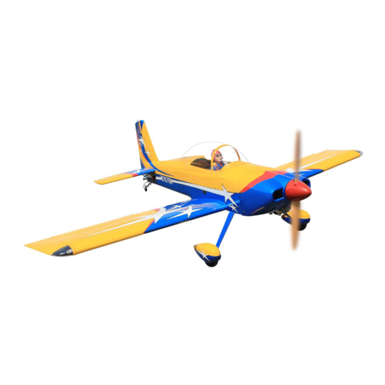
Speciications:
Wingspan------------------------ 180cm------------------------- 71 inches.
Length---------------------------- 152.7cm---------------------- 60 inches.
Wing area------------------------ 64 sq.dm---------------------- 992 sq.in.
Weight---------------------------- 5.8 kg-------------------------- 12.8 lbs.
Engine---------------------------- 35 - 40cc.
Motor 180; 3000-3500watt; ESC 80A-120A; Lipo 12s 3300-4200mAh.
Radio----------------------------- 7 channels 8 servos.
1
Advertisement
Table of Contents

Related Manuals for Seagull Models RV-8


Summary of Contents for Seagull Models RV-8
- Page 1 Code : SEA 388 ASSEMBLY MANUAL Speciications: Wingspan------------------------ 180cm------------------------- 71 inches. Length---------------------------- 152.7cm---------------------- 60 inches. Wing area------------------------ 64 sq.dm---------------------- 992 sq.in. Weight---------------------------- 5.8 kg-------------------------- 12.8 lbs. Engine---------------------------- 35 - 40cc. Motor 180; 3000-3500watt; ESC 80A-120A; Lipo 12s 3300-4200mAh. Radio----------------------------- 7 channels 8 servos.
-
Page 2: Kit Contents
RV-8 ARF 35-40cc Instruction Manual. INTRODUCTION RV-8 ARF 35-40cc RV-8 ARF hank you for choosing the ARTF by SG MODELS. he 35-40cc was designed with the intermediate/advanced sport lyer in mind. It is a semi scale airplane which is easy to ly and quick to assemble. he airframe is conventionally built using balsa, plywood to make it stronger than the average ARTF, yet the design allows the aeroplane to be kept light. -
Page 3: Additional Items Required
KIT CONTENTS HINGING THE FLAP SEA388 RV-8 ARF 35-40cc Note : he control surfaces, including the ailer- ons, elevators, and rudder, are prehinged with 1. Fuselage hinges installed, but the hinges are not glued in 2. Wing set (2) place. It is imperative that you properly adhere 3. -
Page 4: Hinging The Aileron
RV-8 ARF 35-40cc Instruction Manual. Delect the lap and completely saturate Repeat this process with the other wing each hinge with thin C/A glue. he lap front panel, securely hinging the lap in place. surface should lightly contact the wing dur- Ater both lap are securely hinged, irmly ing this procedure. - Page 5 Remove each hinge from the wing panel and aileron and place a T-pin in the center of each hinge. Slide each hinge into the wing CA glue panel until the T-pin is snug against the wing panel. his will help ensure an equal amount of hinge is on either side of the hinge line when the aileron is mounted to the aileron.
- Page 6 RV-8 ARF 35-40cc Instruction Manual. Ater both ailerons are securely hinged, irmly grasp the wing panel and aileron to make sure the hinges are securely glued and cannot be pulled out. Do this by carefully ap- plying medium pressure, trying to separate the aileron from the wing panel.
- Page 7 INSTALL THE AILERONS CONTROL HORN Locate the aileron control horns. he taller control horn is used for the ailerons, and the shorter horn for the laps. Fiberglass control horn Use sandpaper to scuf the bottom of the Epoxy aileron and lap control horns. Use a paper towel and isopropyl alcohol to remove any oils or debris from the control horns.
- Page 8 RV-8 ARF 35-40cc Instruction Manual. Place low-tack tape 1/32 inch (1mm) from the control horn slot. his will pre- vent epoxy from getting on the control surface when the control horns are glued in place. Epoxy Before the epoxy fully cures, remove the tape from around the control horn.
-
Page 9: Installing The Aileron Servos
Minimum servo spec. Torque : 333.00 oz-in (23.98 kg-cm) @ 6.0V; oz-in (29.02 kg-cm) @ 7.4V Install the rubber grommets and brass collets onto the aileron servo. Test it the servo into the aileron servo mount. Because the size of servos difer, you may need to adjust the size of the precut opening in the mount. - Page 10 RV-8 ARF 35-40cc Instruction Manual. Tape the servo lead to the wing to pre- vent it from falling back into the wing. 44mm Reinstall the servo into the servo mount and secure the servo inplace using the wood screws provided with you radio system.
- Page 11 INSTALLING THE AILERON PUSHROD Please study images below. INSTALLING THE FLAP SERVO Repeat the procedure for the lap servo. INSTALLING THE FLAP PUSHROD Repeat the procedure for the aileron pushrod. 70mm...
- Page 12 RV-8 ARF 35-40cc Instruction Manual. Epoxy INSTALL HINGE FOR STABILIZER AND ELEVATOR Please study images below.
- Page 13 INSTALL ELEVATOR CONTROL HORN Fiberglass control horn Epoxy You can cut horizontal and vertical tail holes, please see the image below. Epoxy...
- Page 14 RV-8 ARF 35-40cc Instruction Manual. 32mm Minimum servo spec. Torque : 333.00 oz-in (23.98 kg-cm) @ 6.0V; oz-in (29.02 kg-cm) @ 7.4V...
- Page 15 INSTALL HINGE FOR RUDDER AND INSTALL RUDDER CONTROL HORN Please study images below. Please study images below. 10mm Fiberglass control horn Epoxy Epoxy...
-
Page 16: Horizontal Tail Installation
RV-8 ARF 35-40cc Instruction Manual. HORIZONTAL TAIL INSTALLATION Please study images below. Epoxy... -
Page 17: Elevator Pushrod Installation
M3x12mm ELEVATOR PUSHROD INSTALLATION Please study images below. INSTALL RUDDER CABLE AND SERVO NOTE : servos arm is not provided from manufacturer. 70mm... - Page 18 RV-8 ARF 35-40cc Instruction Manual. Tape the rudder balance tab to the top leading edge of the vertical in in the neutral position as shown. his ensures the rudder is straight when the cables are attached. hread the rudder cable through a...
- Page 19 Feed one rudder cable through the pre installed cable exit tube in the rear of the fuse toward the front of the fuse. Repeat for other side. Cut of excess cable as shown. hread cable through brass swage tube. hread cable through the threaded coupler hole, and back through the brass swage tube as shown.
-
Page 20: Tail Wheel Installation
RV-8 ARF 35-40cc Instruction Manual. Crimp the brass swage tube with a crimping tool or pliers. Cut of excess cable as shown. C/A glue TAILWHEEL INSTALLATION Locate items necessary to install tailwheel. - Page 21 M3x15mm M3x15mm...
- Page 22 RV-8 ARF 35-40cc Instruction Manual. INSTALLING THE MAIN LANDING GEAR TO FUSELAGE Please study images below. M3x4mm...
- Page 23 M3x4mm...
- Page 24 RV-8 ARF 35-40cc Instruction Manual. M3x15mm Loctite M3x15mm M4x20mm...
- Page 25 INSTALLING THE RECEIVER SWITCH Loctite Install the switch into the precut hole in the side, in the fuselage. Trim and cut M4x20mm Switch INSTALLING THE ENGINE SWITCH Trim and cut...
-
Page 26: Fuel Tank Installation
RV-8 ARF 35-40cc Instruction Manual. Switch FUEL TANK INSTALLATION MOUNTING THE ENGINE You should mark which tube is the vent and which is the fuel pickup when you attach fuel tubing to the tubes in the stopper. Once the tank is installed inside the fuselage, it may be diicult to determine which is which. - Page 27 Remove mounting template from irewall. Firewall shown with mounting holes drilled ready for engine mounting. M5x90mm Use a 5.2mm bit to drill the engine mounting holes. 5.2mm Tighten mounting bolts and secure engine to irewall.
-
Page 28: Throttle Servo Installation
RV-8 ARF 35-40cc Instruction Manual. he ire wall has the location for the throttle pushrod tube (pre-drill). Slide the pushrod tube in the irewall and guide it through the fuel tank mount. Use medium C/A to glue the tube to the irewall and the fuel tank mount. -
Page 29: Ignition Installation
Epoxy servo arm Move the throttle stick to the closed po- Install throttle servo into servo mount sition and move the carburetor to closed. ing tray Use a 2.5mm hex wrench to tighten the screw that secures the throttle pushrod wire. - Page 30 RV-8 ARF 35-40cc Instruction Manual. Connect ignition module to pickup line of engine. Secure with Safety Clip, safety wire, tape or other method. Ensure the plugs will not come apart from vibration or light tension. Secure ignition wire with nylon ties as...
- Page 31 COWLING Please study images below. Use a drill and drill bit to drill the holes for the cowl mounting screws. Make sure the cowl position is correct before drilling each hole. Install the muler and muler extension onto the engine and make the cutout in the cowl for muler clearance.
- Page 32 RV-8 ARF 35-40cc Instruction Manual. M3x12mm Recommend the items necessary to install the electric power conversion parts included with your model. - Motor: 180cc - 195 KV - Propeller: 27 x 10 - ESC: 80-120A - 12S- 14S Lipo ELECTRIC POWER CONVERSION...
- Page 33 Attach the electric motor box to the ire- wall centered with the cross lines drawn on the electric motor box and irewall. Using M5x35mm to secure the motor box to the irewall. Please see pictures below. M5x35mm and washers Attach the motor to the front of the elec- tric motor box using four 4mm blind nut, four M5x35mm hex head bolts to secure the motor.
- Page 34 RV-8 ARF 35-40cc Instruction Manual. M5x25mm 160mm hen, use 5mm drill bit to enlarge the holes on the electric motor box. 6.5mm Attach the speed control to the side of the motor box using two-sided tape and Attach the motor mount to the front tie wraps.
-
Page 35: Installing The Spinner
Battery INSTALLING THE SPINNER Install the spinner backplate, propeller and spinner cone. he propeller should not touch any part of the spinner cone. If it does, use a sharp modeling knife and carefully trim away the spinner cone where the propel- ler comes in contact with it. - Page 36 RV-8 ARF 35-40cc Instruction Manual. INSTALLATION PILOT AND CANOPY Epoxy Locate items necessary to install pilot and canopy. 150mm Epoxy canopy onto the fuselage. Trace around the canopy and onto the fuselage using a epoxy. A scale pilot is included with this ARF.
- Page 37 Wrap the receiver and battery pack in the protective foam rubber to protect them from vibration. Route the antenna in the antenna tube inside the fuselage and secure it to the bottom of fuselage using a plastic tape. Battery Receiver ATTACHMENT WING - FUSELAGE Attach the aluminium tube into fuselage.
-
Page 38: Apply The Decals
RV-8 ARF 35-40cc Instruction Manual. *If possible, irst attempt to balance the APPLY THE DECALS model by changing the position of the re- ceiver battery and receiver. If you are un- 1) If all the decals are precut and ready to able to obtain good balance by doing so, stick. - Page 39 70-140mm 70-140mm 60-120mm Fuselage 60-120mm 40-80mm Wing 40-80mm 40mm 80mm...
-
Page 40: Flight Preparation
2) Check every bolt and every glue A) Plug in your radio system per the joint in the RV-8 ARF 35-40cc to en- manufacturer’s instructions and turn sure that everything is tight and well everything on. - Page 41 If you have any queries, or are interested in our products, please feel free to contact us Factory : 12/101A - Hamlet 4 - Le Van Khuong Street - Dong hanh Ward - Hoc Mon District - Ho Chi Minh City - Viet Nam. Oice : 62/8 Ngo Tat To Street - Ward 19 - Binh hanh District - Ho Chi Minh City - Viet Nam Phone : 848 - 86622289 or 848- 36018777...
Need help?
Do you have a question about the RV-8 and is the answer not in the manual?
Questions and answers