
Related Manuals for Solax TRIPLE POWER TP-LD53


Summary of Contents for Solax TRIPLE POWER TP-LD53
- Page 1 TP-LD53 User Manual Version 1.0 www.solaxpower.com eManual in the QR code or at http://kb.solaxpower.com/...
- Page 3 No part of this manual may be reproduced, transmitted, transcribed, stored in a retrieval system, or translated into any language or computer language, in any form or by any means without the prior written permission of SolaX Power Technology (Zhejiang) Co., Ltd. Trademarks and other symbol or design (brand name, logo) that distinguishes the products or services offered by SolaX has been trademark protected.
- Page 4 About This Manual Scope of Validity This manual is an integral part of T-BAT Series. It describes the installation, electrical connection, commissioning, maintenance and troubleshooting of the product. Please read it carefully before operating. Battery Module TP-LD53 Note: In the case of floor mounting, it contains battery module(s) only. In the case of wall mounting, it contains battery module(s) and wall bracket(s).
- Page 5 Conventions The symbols that may be found in this manual are defined as follows. Symbol Description Indicates a hazardous situation which, if not avoided, DANGER will result in death or serious injury. Indicates a hazardous situation which, if not avoided, WARNING could result in death or serious injury.
-
Page 6: Table Of Contents
Table of Contents Safety ......................1 1.1 General Safety ........................1 1.2 General Safety Precautions ....................2 1.3 Battery Handling Guide....................2 1.4 Response to Emergency Situations ................3 Product Overview ..................5 2.1 System Description ......................5 2.2 Appearance, Weight and Dimensions .................5 2.2.1 Label .........................7 2.2.2 Electrical Connection Area ................8 2.2.3 Indicator Panel ......................11 2.3 Symbols on the Label .......................15... - Page 7 7.3 Communication Connection..................47 7.4 Ring Terminal Installation ....................48 7.5 Female Connector Installation ..................49 7.6 Wiring Procedure .......................52 7.6.1 The Right Electrical Connection Area of the Battery Module Selected to Be Connected to the Inverter ................53 7.6.2 The Left Electrical Connection Area of the Battery Module Selected to Be Connected to the Inverter ................60 System Commissioning ................67 8.1 Checking before Power-on ....................67...
-
Page 9: Safety
And the safety instructions in this document are only supplements to local laws and regulations. SolaX shall not be liable for any consequences caused by the violation of the storage, transportation, installation, and operation regulations specified in this document, including, but not limited to: •... -
Page 10: General Safety Precautions
Safety General Safety Precautions • Overvoltage or wrong wiring may damage the battery module and cause combustion which may be extremely dangerous; • Leakage of electrolytes or flammable gas may be occurred due to any type of product breakdown; • Do not install the battery module in places where flammable and combustible materials are stored, and in which an explosive atmosphere is present;... -
Page 11: Response To Emergency Situations
Safety penetrating with a sharp object. Otherwise, it may cause a fire or leakage of electrolytes; • DON'T touch the device if liquid spill on it. There is a risk of electric shock; • DON'T step on the packaging or the device may be damaged; •... - Page 12 DON'T use the submerged battery module again, and contact the qualified personnel for assistance. • DO contact SolaX immediately for assistance if the user suspects that the battery module is damaged. WARNING! • Do not crush or impact battery, and always dispose of it according to relevant safety regulations.
-
Page 13: Product Overview
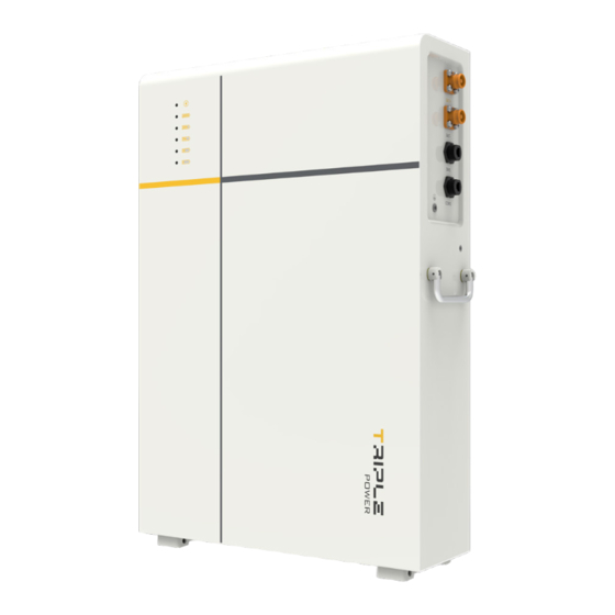
Product Overview WARNING! • The bi-directional energy storage inverter connected with the battery module must be an isolated inverter. System Description The battery system consists of one or more rechargeable batteries. A battery module is a type of electrical battery which can charge or discharge loads. There are two installation options, such as floor mounting and wall mounting, that a user can select from. - Page 14 Product Overview Table 2-1 Description of appearance Item Description Including performance label, which clearly identifies the device type, “Label” serial number, parameters, certification, etc., and manufacturer label describing name and address of manufacturer. Including BAT+/BAT- ports, communication port, BMS port, Electrical grounding port, DIP, and POWER button.
-
Page 15: Label
Certified to UN38.3 / IEC 62619 / CE DANGER / HIGH VOLTAGE INSIDE Serial number SolaX Power Network Technology (Zhejiang) Co., Ltd. ADD.: No. 288, Shizhu Road, Tonglu Economic Development Zone, Tonglu City, Zhejiang Province, 310000 P.R. CHINA TEL: +86 571 5626 0011 E-mail: info@solaxpower.com... -
Page 16: Electrical Connection Area
Product Overview 2.2.2 Electrical Connection Area Figure 2-4 Right side of battery module Table 2-3 Description of ports and keys Item Description Power button: Start/shut down system. BAT+/BAT- port: Connect to the BAT+/BAT- port of the inverter or the adjacent battery module. - Page 17 Product Overview Figure 2-5 Left side of battery module Table 2-4 Description of ports Item Description BAT+/BAT- port: Connect to the BAT+/BAT- port of the inverter or the adjacent battery module "BMS" port: Connect to the "BMS" port of the inverter, or it doesn't need to be connected.
- Page 18 Product Overview DIP Switch A DIP Switch is actually a set of small manual electronic switches that are designed to be packaged with other circuits. It is currently equipped with the battery module. The location of the DIP switch and the factory defaults are shown as below. Figure 2-6 DIP Switch Default Configuration Terminal resistance...
-
Page 19: Indicator Panel
Product Overview 2.2.3 Indicator Panel The battery module is equipped with a monochrome status light (blue) and five tri-colour SOC power indicators (green/yellow/red) to show its operating status. The SOC power indicators show the current battery percentage. Status Light SOC5 100% SOC4 SOC power... - Page 20 Product Overview NOTICE! • The function of Self Test will be performed when users turn the system on, with a duration of 11 seconds. In the meantime, the status light will remain on solid yellow light, and the SOC power indicators will remain on solid blue light based on their actual remaining capacity.
- Page 21 Product Overview NOTICE! • When the charging current is less than or equal to 1 A, the SOC indicators will remian on solid blue light. • When the charging current is over 1 A, the SOC indicators will flash blue lights. If more than two battery modules (including two) are purchased, the circumstance that some of the battery modules' SOC indicators may flash blue and the remaining battery modules' SOC indicators may remain on solid blue, may occur.
- Page 22 Product Overview Black Start The equipment can provide Black Start capacity, meaning that our energy storage inverter and battery can continue to run even if the power grid and photovoltaic panel are out of service. The startup procedure for Black Start is as follows: •...
-
Page 23: Symbols On The Label
Product Overview Symbols on the Label Table 2-8 Description of symbols Symbol Description CE mark. The rechargeable battery complies with the requirements of the applicable CE guidelines. TUV certified. The battery system must be disposed of at a proper facility for environmentally-safe recycling. -
Page 24: Features
Product Overview Features The T-BAT-SYS-LD is one of the most advanced energy storage systems on the market today, using state-of-the-art technology, and having the characteristics of high reliability and convenient control. Characteristics are shown as follows: • 90% DOD; • 95% Battery Round-trip Efficiency;... -
Page 25: Transportation And Storage
Transportation and Storage If the rechargeable battery are not put into use immediately, the transportation and storage requirements needs to be met: Transportation • Observe the caution signs on the packaging of battery before transportation. • Pay attention to the weight of the rechargeable battery. Be cautious to avoid injury when carrying battery module (TP-LD53). - Page 26 Transportation and Storage Storage • Do not remove the original packaging material and check the outer packaging material regularly. • The required storage temperature: the service life may be up to 6 months in case the temperature is between 30°C and +50°C, or it may be up to 12 months in case the temperature is between -20°C and +30°C.
-
Page 27: Preparation Before Installation
Preparation before Installation Selection of Installation Location The installation location selected for the rechargeable battery is quite critical in the aspect of the guarantee of machine safety, service life and performance. • It has the IP65 ingress protection, which allows it to be installed outdoor; •... -
Page 28: Installation Carrier Requirement
Preparation before Installation -20°C-+53°C IP6 5 5-95%RH No direct sunlight No rain exposure No snow lay up Near combustibles Direct sunlight Rain exposure Snow lay up Near antenna 4.1.2 Installation Carrier Requirement The mounting location must be suitable for the weight and dimensions of the product and the support surface for installation must be made of a non-flammable material. -
Page 29: Clearance Requirement
Preparation before Installation 4.1.3 Clearance Requirement To guarantee proper heat dissipation and ease of disassembly, the minimum space around the rechargeable battery must meet the standards indicated below. • No matter which floor mounting or wall mounting is chosen, a distance between 200 and 300 mm wide shall be provided from the wall to the edge of the battery module. - Page 30 Preparation before Installation 200 mm ~300 mm Solid brick wall concrete wall 400 mm ~ 600 mm 300 mm ~ 350 mm Elevation view Solid brick or concrete wall with a minimum thickness of 100 mm Solid brick wall 55 mm concrete wall 400 mm ~ 600 mm Battery module...
-
Page 31: Tools Requirement
Preparation before Installation Tools Requirement Installation tools include but are not limited to the following recommended ones. If necessary, use other auxiliary tools on site. Ø12 mm Heat Hammer drill Measuring tape Marker shrink tubing Torque wrench Rubber mallet Heat gun Crimping tool for RJ45 Wire stripper Hydraulic wire crimper... -
Page 32: Unpacking And Inspection
Unpacking and Inspection Unpacking • The rechargeable battery undergoes 100% testing and inspection before shipping from the manufacturing facility. However, transport damage may still occur. Before unpacking the rechargeable battery, please verify that the model and outer packing materials for damage, such as holes and cracks. •... -
Page 33: Scope Of Delivery
Unpacking and Inspection Scope of Delivery One Battery Module (TP-LD53) Power cable (orange) Power cable (black) Battery module Wall bracket (2000 mm) (2000 mm) Communication cable (2000 mm) L-shaped wall bracket Waterproof plug Ring terminal Expansion bolt M6*12 Cross external Expansion screw Self-tapping screw hexagon screw... - Page 34 • The above items are only for one battery module. Our company will provide corresponding components according to the battery modules. • The accessory with the superscript "¹" indicates that SolaX will give the user two extra free accessories away.
-
Page 35: Mechanical Installation
Mechanical Installation Installation Options There are two installation options (floor mounting and wall mounting) are available, with details as follows: Option A: Floor Mounting 500 mm Option B: Wall Mounting 500 mm Figure 6-1 Installation options NOTICE! • The Figure 6-1 takes two battery modules as an example. •... -
Page 36: Installation Procedure
Mechanical Installation Installation Procedure WARNING! • Only the qualified personnel can perform the mechanical installation following the local standards and requirements. • Check the existing power cables or other piping in the wall to prevent electric shock or other damage. •... -
Page 37: Floor Mounting
Mechanical Installation 6.2.1 Floor Mounting WARNING! • The site for installing the battery module must be level (no slope, no pothole). NOTICE! • Allow sufficient clearance between adjacent walls or equipment for proper installation of the battery module. • The following steps take one (1) battery module as an example. Step 1: Fix the L-shaped wall bracket (Part D) to the battery module with M6*12 cross external hexagon screw (Part J) (×... - Page 38 Mechanical Installation Step 2: Locate the L-shaped wall bracket against the wall. Concrete wall or 55 mm solid brick wall with a minimum thickness of 100 Front view Left side view Figure 6-3 Locating the battery module against the wall NOTICE! •...
- Page 39 Mechanical Installation Step 4: Drill two holes at a depth of more than 60 mm in the concrete wall (or solid brick wall) by using a Drill (Ø8 mm). Concrete wall or solid brick wall with a minimum thickness of 100 mm Ø8 mm Drill 90°...
- Page 40 Mechanical Installation Step 5: Insert the expansion bolt (Part H) (× 2 pcs) into the two holes. Figure 6-6 Inserting expansion bolts Step 6: Gently move the battery module against the wall, and align the holes drilled previously. Correctly insert and tighten self-tapping screw (Part I) (× 2 pcs) to secure the L-shaped wall bracket on both sides to the wall (Tightening torque: 6-8 N·m).
- Page 41 Mechanical Installation M6 × 12 6-8 N·m 6-8 N·m 4-5 N·m Figure 6-7 Tightening tapping screws and M6 screws NOTICE! • At least two persons are required to lift the battery module.
- Page 42 Mechanical Installation Step 7: Repeat steps 1 to 6 to install the second battery module, as well as the remaining battery modules (if any) . Refer to steps 1 to 6 400 mm ~ 600 mm Figure 6-8 Installing the remaining battery module NOTICE! •...
-
Page 43: Wall Mounting
Mechanical Installation 6.2.2 Wall Mounting Step 1: Attach the wall bracket to the wall, and make sure that it is level via the cylindrical plastic bubble spirit level on the bracket. Draw a circle along the inner ring, with a total of 4 circles. 300 mm ~ 350 mm Cylindrical plastic bubble spirit level Figure 6-9 Drawing circles... - Page 44 Mechanical Installation Step 2: Remove the wall bracket, and then drill four holes at a depth of more than 90 mm in the concrete wall (or solid brick wall) by using a Drill (Ø12 mm). Concrete wall or solid brick wall with a minimum thickness of 100 mm Ø12 mm Drill...
- Page 45 Mechanical Installation Step 3: Attach the wall bracket to the wall again, and correctly insert and tighten expansion screw (Part G) (× 4 pcs) to secure the wall bracket (Tightening torque: 14-16 N·m). 14-16 N·m Figure 6-11 Tightening expansion screw NOTICE! •...
- Page 46 Mechanical Installation Step 4: Fix the L-shaped wall bracket (Part D) to the battery module with M6*12 cross external hexagon screw (Part J) (× 2 pcs), but do not tighten them fully. L-shaped wall bracket M6 screw Figure 6-12 Fixing L-shaped wall bracket to the battery module NOTICE! •...
- Page 47 Mechanical Installation NOTICE! • At least two persons are required to lift the battery module. • The battery module shall be located against the wall bracket. Step 6: Draw a circle along the inner ring, with one on each side. Then gently carry the battery module down to the ground.
- Page 48 Mechanical Installation Step 7: Drill two holes at a depth of more than 60 mm in the concrete wall (or solid brick wall) by using a Drill (Ø8 mm). Concrete wall or solid brick wall with a minimum thickness of 100 mm Ø8 mm Drill 90°...
- Page 49 Mechanical Installation Step 8: Insert the expansion bolt (Part H) (× 2 pcs) into the two holes. Figure 6-16 Insert expansion bolts...
- Page 50 Mechanical Installation Step 9: Gently lift the battery module onto the wall bracket, and locate it against the wall bracket. Correctly insert and tighten self-tapping screw (Part I) (× 2 pcs) to secure the L-shaped wall bracket on both sides to the wall (Tightening torque: 6-8 N·m). Fully tighten the M6*12 cross external hexagon screw (Part J) (×...
- Page 51 Mechanical Installation Step 10: Repeat steps 1 to 9 to install the second battery module, as well as the remaining battery modules (if any) . Refer to steps 1 to 9 400 mm ~ 600 mm Figure 6-18 Installing the remaining battery module NOTICE! •...
-
Page 52: Wiring
Wiring NOTICE! • Regarding the PE and communication cable, of which one end connects to the inverter, it shall be made before conducting wiring. • Regarding the power cable connecting two adjacent battery modules, the female connector onto the power cable must be made before conducting wiring. Details of Cables Cables in the Accessories Kit for Battery Module Table 7-4 Details of cables... -
Page 53: Pe Connection
Wiring Table 7-5 Details of cables There are two terminals at both ends: one connects to the "COM1" port of the battery 1 pc module, and the other connects to the Communication cable 1000 mm "COM2" port of the adjacent battery modules. PE Connection The steps for making PE connection are shown as follows: Step 1:... - Page 54 Wiring Step 3: Crimp the terminal, and heat the heat-shrink tubing after it wraps the end of terminal. Figure 7-3 Crimping and heating Step 4: Unscrew the M5 screw, and then connect the assembled grounding cable to the grounding port of the battery module, and then tighten M5 screw (Tightening torque: 2.5-3 N·m).
-
Page 55: Communication Connection
Wiring Communication Connection To ensure normal operation between the battery module and inverter, the communication cable connecting from the battery module to the inverter is required to connect RJ45 connector. Make sure that the "BMS" port on the battery module connects to the inverter is Pin to Pin. The "BMS"... -
Page 56: Ring Terminal Installation
Wiring NOTICE! • The communication cable shall have a shield layer. • The communication cable is delivered with the Accessories Kit for Cables. Ring Terminal Installation Ring terminals are connectors for power cables. They are designed to connect the end of a power cable to a circuit point. -
Page 57: Female Connector Installation
Wiring NOTICE! • Properly place the ring terminal into the MC4 crimping tool. Step 3: Make the positive power cable according to the above two steps. Negative power cable Positive power cable Figure 7-9 Making power cables NOTICE! • The ring terminals are delivered with the inverter's accessories kit. •... - Page 58 Wiring Cable seal ring Tail cover Figure 7-11 Inserting the stripped wire Step 3: With care, strip the cable jacket about 15±1 mm from the end. 15 ± 1 mm Conductor Cable jacket Wire stripper Figure 7-12 Striping cable jacket NOTICE! •...
- Page 59 Wiring NOTICE! • Properly place the plastic housing into a hydraulic wire crimper. • DO NOT place the conductor insulation into the connector body. • DO NOT crush the plastic housing while crimping. • DO NOT crush or damage the conductor insulation while crimping. Step 5: Orderly push the cable seal ring and tail cover into the body.
-
Page 60: Wiring Procedure
Wiring Lock button Figure 7-16 Lock button NOTICE! • The Figure 7-16 is the power cable that finishes the installation of the female connector. • Press and hold the "Lock button" while unplugging the power cable. Otherwise, it cannot be pulled out. •... -
Page 61: The Right Electrical Connection Area Of The Battery Module Selected To Be Connected To The Inverter
Wiring 7.6.1 The Right Electrical Connection Area of the Battery Module Selected to Be Connected to the Inverter Cable connection for only one battery module Step 1: Connect the negative power cable to the "BAT-" ports of the battery module and inverter. - Page 62 Wiring Inverter Communication cable Power cable (black) Power cable (orange) Click Waterproof Grounding cable Right side view Figure 7-17 Cable connection of the right electrical connection area NOTICE! • Regarding the making process of grounding cable, please refer to “PE Connection”.
- Page 63 Wiring Step 2: Cover "BAT+" and "BAT-" ports with waterproof plugs (Part E), as well as "BMS" and "COM1" ports with waterproof caps. Waterproof plug Waterproof cap Left side view Figure 7-18 Left electrical area of the battery module Tip: Use safety gloves when connecting battery modules. Cable connection for two or more battery modules Since the wiring procedure of two battery modules is the same as that of more than two battery modules, the wiring procedure of two battery modules is taken as an example.
- Page 64 Wiring Inverter Right electrical Two adjacent Left electrical connection area battery modules connection area Figure 7-19 Wiring diagram of two battery modules The detailed connection procedure is shown as follows: Step 1: Connect the negative power cable to the "BAT-" ports of the battery module and inverter.
- Page 65 Wiring Inverter Communication cable Power cable (black) Power cable (orange) Click Waterproof Grounding cable Right side view Figure 7-20 Cable connection of the right electrical connection area NOTICE! • Regarding the making process of grounding cable, please refer to “PE Connection”.
- Page 66 Wiring Step 2: Connect the negative power cable to the "BAT-" ports of adjacent battery modules. Connect the positive power cable to the "BAT+" ports of adjacent battery modules. Connect the communication cable (Part B1) to the "BMS" ports of adjacent battery modules.
- Page 67 Wiring NOTICE! • Regarding the making process of power cable, please refer to “Installation of Female Connector onto Power Cable”. • A corrugated pipe with an external diameter of 60 mm is recommended for use to keep cable insulation in place and avoid potential damages, when conducting wiring between two adjacent battery modules.
-
Page 68: The Left Electrical Connection Area Of The Battery Module Selected To Be Connected To The Inverter
Wiring 7.6.2 The Left Electrical Connection Area of the Battery Module Selected to Be Connected to the Inverter Cable connection for only one battery module Step 1: Connect the negative power cable to the "BAT-" ports of the battery module and inverter. - Page 69 Wiring Inverter Communication cable Power cable (black) Power cable (orange) Click Waterproof Grounding cable Left side view Figure 7-23 Cable connection of the left electrical connection area NOTICE! • Regarding the making process of grounding cable, please refer to “PE Connection”.
- Page 70 Wiring Step 2: Cover "BAT+" and "BAT-" ports with waterproof plugs (Part E), as well as "BMS" and "COM1" ports with waterproof caps. Waterproof plug Waterproof cap Right side view Figure 7-24 Right electrical connection area of the battery module Tip: Use safety gloves when connecting battery modules.
- Page 71 Wiring Cable connection for two or more battery modules Since the wiring procedure of two battery modules is the same as that of more than two battery modules, the wiring procedure of two battery modules is taken as an example. The general wiring diagram of two battery modules is shown below: Inverter Right electrical...
- Page 72 Wiring Inverter Communication cable Power cable (black) Power cable (orange) Click Waterproof Grounding cable Left side view Figure 7-26 Cable connection of the left electrical connection area NOTICE! • Regarding the making process of grounding cable, please refer to “PE Connection”.
- Page 73 Wiring Step 2: Connect the negative power cable to the "BAT-" ports of adjacent battery modules. Connect the positive power cable to the "BAT+" ports of adjacent battery modules. Connect the communication cable (Part B1) to the "BMS" ports of adjacent battery modules.
- Page 74 Wiring NOTICE! • Regarding the making process of power cable, please refer to “Installation of Female Connector onto Power Cable”. • A corrugated pipe with an external diameter of 60 mm is recommended for use to keep cable insulation in place and avoid potential damages, when conducting wiring between two adjacent battery modules.
-
Page 75: System Commissioning
System Commissioning Checking before Power-on Check the device installed correctly and securely; Make sure that Power button is OFF; All cables are connected correctly and securely; All unconnected port are covered; Powering on/off the System Power on: Press and hold the POWER button on the right electrical connection area of the battery module that connects to the inverter until the LED lights appear. - Page 76 System Commissioning NOTICE! • Regarding the first start, after pressing and holding the POWER button on the battery module that connects to the inverter for 15 seconds, the battery system will assign each battery module in a communication loop a unique address (battery number).
-
Page 77: Troubleshooting And Maintenance
Therefore, when a warning is reported, the inverter will stop working immediately. Contact SolaX Customer Service for further assistance. Please be prepared to describe the details of your system installation and provide the model and serial number of the rechargeable battery. - Page 78 Troubleshooting and Maintenance Error Code Fault Diagnosis and Solution Total voltage overvoltage: • Tap "Power Off" on the inverter Total voltage BMS_HVB_OVER_FAULT screen until the fault is rectified. overvoltage fault • Contact the after-sales personnel of our company. Total voltage undervoltage: •...
- Page 79 Troubleshooting and Maintenance Error Code Fault Diagnosis and Solution Discharge overcurrent of BMS: Discharge • Restart the BMS. BMS_DSG_OVER_FAULT overcurrent of • Contact the after-sales personnel of our company. Overcurrent charging of BMS: Overcurrent • Restart the BMS. BMS_CHG_OVER_FAULT charging of BMS •...
- Page 80 Troubleshooting and Maintenance Error Code Fault Diagnosis and Solution Inverter does not respond the charging request. Charging request BMS_CHG_REQ_FAULT • Restart the BMS or the inverter. not responded • Contact the after-sales personnel of our company. Communication loss of the BMS: •...
-
Page 81: Maintenance
6 months. If the manufacture date of the new one exceeds 6 months, please charge it to around 40%. WARNING! • Only qualified person can perform the maintenance for the rechargeable battery. • Only use the spare parts and accessories approved by SolaX for maintenance. -
Page 82: 10 Decommissioning
10 Decommissioning 10.1 Disassembling the Battery WARNING! • Before unplugging the cables, ensure that your hands are dry and free from moisture. This will help prevent electrical shock and ensure a secure grip on the plug. • When disassembling the battery, strictly follow the steps as below. NOTICE! •... - Page 83 Decommissioning Step 2: Hold down two lock buttons on both sides of the connector firmly to unplug the power cable. Avoid pulling on the cable itself, as this can potentially damage the cable and the port on the battery module. Lock button Lock button Figure 10-2 Unplugging power cables...
-
Page 84: Packing
Decommissioning Step 4: Unscrew the screws counter-clockwise to remove the grounding cable. 2.5-3 N·m Figure 10-4 Removing grounding cable 10.2 Packing • Load the battery module into the original packing material if possible. • If the original packing material is not available, you can also use the packing material which meets the following requirements: »... -
Page 85: 11 Technical Data
11 Technical Data Parameter Display Battery Module TP-LD53 Nominal Voltage (Vdc) 51.2 Operating Voltage (Vdc) 45-58 Nominal Capacity (Ah)¹ Nominal Energy (kWh)¹ 5.32 Usable Energy 90% DOD (kWh)² Max. Output Current (A)³ Peak Charge/Discharge Current (A)⁴ 200 (10 seconds) Battery Round-trip Efficiency (0.2C, 25°C) Warranty Period 5 years Cycle Life 90% DOD (25°C) - Page 86 Contact Information UNITED KINGDOM AUSTRALIA Unit C-D Riversdale House, Riversdale 21 Nicholas Dr, Dandenong South VIC 3175 Road, Atherstone, CV9 1FA +61 1300 476 529 +44 (0) 2476 586 998 service@solaxpower.com service.uk@solaxpower.com TURKEY GERMANY KIZILSARAY MAH. 76 SK. LATİF AYKUT Am Tullnaupark 8, 90402 Nürnberg, İŞMERKEZİ...
- Page 87 SolaX Power Network Technology (Zhejiang) Co., Ltd. Add.: No. 288, Shizhu Road, Tonglu Economic Development Zone, Tonglu City, Zhejiang Province, 310000 P. R. CHINA Tel.: +86 (0) 571-56260011 E-mail: info@solaxpower.com / service@solaxpower.com Copyright © SolaX Power Technology (Zhejiang) Co., Ltd. All rights reserved. 320101087201...
Need help?
Do you have a question about the TRIPLE POWER TP-LD53 and is the answer not in the manual?
Questions and answers
Is Temperature and overload/short circuit protection available in TP-LD53
YES. The Solax TRIPLE POWER TP-LD53 has temperature protection, as it specifies operating temperature ranges for charging, discharging, and storage. Overload/short circuit protection is implied through the Battery Management System (BMS), which monitors conditions like overvoltage and undervoltage and triggers warnings to protect the system.
This answer is automatically generated
is display screen available and monitoring via net is possible in TP-LD53