Advertisement
Quick Links
Advertisement

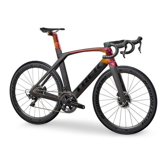
Summary of Contents for Trek MADONE 2019
- Page 1 2019 MADONE ASSEMBLY MANUAL...
- Page 2 2019 MADONE Rim brakes and Di2 drivetrain Disc brakes and Di2 drivetrain Disc brakes and mechanical drivetrain Rim brakes and mechanical drivetrain...
- Page 3 PROCEDURES COMMON TO ALL 2019 MADONE MODELS TABLE OF CONTENTS Install the chain keeper at the base of the front NOTE derailleur hanger. Torque the bolt to 3 Nm. There is plastic tubing inside the frame to help with the initial routing of the cables and housings through the frame.
-
Page 4: Tools And Materials Required
INSTALL THE MECHANICAL CONTROL CENTRE Install the rear derailleur on the the rear derailleur If you are planning to use the 5 mm spacer recessed TOOLS AND MATERIALS REQUIRED hanger. Tighten to the OEM torque spec. in the stem, your actual cutting line should be 5 mm below the pencil mark made in the prior step. - Page 5 Route the RD cable/housing from the head tube to the Install the bottom bracket guide and hold it in place Route the RD cable from the bottom bracket hole cutout in the downtube. with the FD cable. up through the drive-side chainstay and out the rear hole in the chainstay.
- Page 6 INSTALL THE DI2 CABLES AND HOUSINGS TOOLS AND MATERIALS REQUIRED Install the short cable housing from the rear Put the RD cable in the rear derailleur cable anchor • Park Tool – Internal Cable Routing Kit (IR-1 or IR-1.2) • Junction B Box (SM JC41) •...
- Page 7 INSTALL THE REAR DISC BRAKE (MECHANICAL DRIVETRAIN) B. Do not over-tighten the zip ties. Snug them up Route the rear brake hose enough to stay in the control centre groove, but A. Slip the rubber grommet onto the brake hose. loose enough so that the hose can slide in the channel.
- Page 8 INSTALL THE REAR DISC BRAKE (Di2 DRIVETRAIN) Connect the control centre to the downtube. Torque Route the rear brake hose Feed the RB hose up through the downtube towards the bolts to 3-4 Nm. the head tube. A. Slip the rubber grommet onto the brake hose. B.
- Page 9 INSTALL THE FRONT DISC BRAKE ROUTE THE REAR RIM BRAKE HOUSING TOOLS AND MATERIALS REQUIRED Route the front brake hose • Park Tool Routing Kit (IR-1 or IR-1.2) • Foam sleeve • Electrical tape A. Put soap or grease on the brake hose for ease of installation (approximately 200 mm).
- Page 10 INSTALL THE FORK AND HEADSET TOOLS AND MATERIALS REQUIRED Pass the RB housing through the foam sleeve so that Tape the housing flush with the seat tube. • Tape there is 200 mm of housing beyond the rear end of the sleeve.
- Page 11 Arrange the housings in the head tube prior to Interlock the required spacers and slide them down Make sure that installing the upper head tube bearing. the steerer tube to interface with the bearing top the RB hose is not kinked. cap.
- Page 12 INSTALL THE STEM (MECHANICAL DRIVETRAIN) INSTALL THE STEM (Di2 DRIVETRAIN) Feed the FB & RB hoses and FD & RD housings through Install the expander into the fork. Follow the Connect the JC200 connector to the short end of the Install the stem onto the steerer tube.
- Page 13 INSTALL THE HANDLEBAR AND SHIFT LEVERS AT THIS POINT, YOU SHOULD HAVE A COMBINATION OF FOUR POSSIBLE CONFIGURATIONS: As the bike is orientated upright, the RB housing Attach the stem faceplate. Install the rear two bolts Drivetrain Brakes Configuration should be on the top of all other housings coming out first.
- Page 14 INSTALL THE SHIFT LEVERS Now add on your insertion depth from Step 1, plus Re-install the FD housing ferrule. another 10-20 mm. On the drive side, insert the RD housing and the RB On the drive side, push the shift lever back up on housing into the applicable locations in the shifter Example for rear brake: the handlebar to the desired location while inserting...
- Page 15 INSTALL THE FRONT RIM BRAKE ADJUST THE FRONT RIM BRAKE Pull the front brake cable a safe distance back from the With the fork turned to full left, route the brake cable With the fork turned to full left, slide the brake wedge Remove the wedge from between the rollers and slide housing end.
- Page 16 INSTALL THE REAR RIM BRAKE TOOLS AND MATERIALS REQUIRED Squeeze the brake lever fully to seat the housing and Use the appropriate centring bolt to make the final • Housing stop and bolt • Cable cutter to stretch the brake cable. centring adjustment.
- Page 17 INSTALL AND ADJUST THE SEATPOST TOOLS AND MATERIALS REQUIRED Pass the brake cable and lined end cap into the rear • Saddle • Seatpost wedge and bolts • Long stem 5 mm hex wrench brake housing stop. • Seatpost • Lower seal •...
-
Page 18: Tools Required
ADJUST THE ISOSPEED SYSTEM TOOLS REQUIRED To adjust the fore/aft position of the saddle, loosen the • 2.5mm Allen™ key • 4 mm Allen™ key side rail clamp bolt, slide the saddle, then re-tighten the bolt. From the rear base of the seatmast, use the 2.5mm Reference the slider decal to help determine the Allen™... -
Page 19: Fit Measurements
FIT MEASUREMENTS SERVICE INFORMATION Saddle X Saddle set-back Saddle tilt Di2 Handlebar Specifications for Reference Handlebar X Frame Size Bar Size Y-Wire Spec Charge port to DS Shifter Saddle-to-bar drop Saddle Y SD50 -[350 mm] Saddle height (BB to top centre of saddle) Handlebar Y JC130-SM [350 mm/50 mm/450 JC130-MM [550mm/50... -
Page 20: Service Notes
SERVICE NOTES date miles/km hours... - Page 21 PN 577340...


Need help?
Do you have a question about the MADONE 2019 and is the answer not in the manual?
Questions and answers