
Related Manuals for Samsung MIM-N10


Summary of Contents for Samsung MIM-N10
- Page 1 ERV (Energy Recovery Ventilator) Installation manual ERV interface module MIM-N10 Thank you for purchasing this Samsung Product. Before operating this unit, please read this installation manual carefully and retain it for future reference.
-
Page 2: Safety Information
Safety Information This installation manual explains how to install an ERV interface module that is connected to a Samsung Ventilator. Please read this manual thoroughly before installing the product. (Please refer to an appropriate installation manual for any optional product installation.) WARNING Hazards or unsafe practices that may result in severe personal injury or death. - Page 3 ERV interface module installation Products and components Case ERV interface DC power cable Communication Name Cable tie module (12 V) cable Outdoor unit Indoor unit Shape Diagram of connection between an ERV interface module and a Ventilator 1. Attach the ERV interface module in the space within the electrical parts of the ventilator. 2.
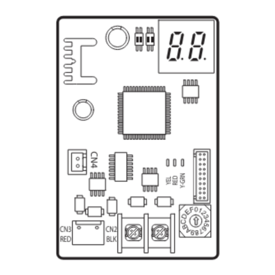
- Page 4 ERV interface module installation Diagram of connection between an ERV interface module and a Ventilator 3. Set the address of ERV interface module. The address for each ERV interface module should be set differently. CAUTION Setting option switch and address switch SW4 SW5 Address switch for ERV interface module...
- Page 5 Setting option switch and address switch About setting the main address manually and installation condition 1. Connecting NASA communication upper level controller SW4 SW5 NASA Non-NASA Manual address Automatic address communication ERV communication ERV 1 2 1 2 No function Automatic address: Address of the interface module is assigned randomly.
-
Page 6: Checking Operation
ERV interface module installation When installing 16 Ventilators OnOff controller Ventilator Ventilator Ventilator Ventilator Ventilator RMC:0 RMC:1 RMC:2 RMC:E RMC:F Ventilator ERV interface module (3~D) RMC number of the Ventilator Bottom number of the OnOff controller Checking operation LED Indication 1. When resetting the power supply, the ERV interface module will not respond to the upper level communication for up to 10 minutes. - Page 7 Checking operation 7-SEGMENT indication 1. When initializing power supply, will be indicated after indicating the program cord. 2. After receiving valid communication more than once, will be indicated. 3. When the communication is normal, the MAIN ADDRESS of the ventilator that can be controlled by the ERV interface module is indicated in order.
- Page 8 (For India only) For more information on safe disposal and recycling, visit our website www.samsung.com/in/support or contact our Helpline numbers - 1800 40 SAMSUNG (1800 40 7267864) 1800 5 SAMSUNG (1800 5 7267864).