Table of Contents
Advertisement
Available languages
Available languages
Quick Links
Advertisement
Table of Contents

Related Manuals for HUANUO HNDSK4


Summary of Contents for HUANUO HNDSK4
- Page 1 INSTRUCTION MANUAL MANUEL D'UTILISATION Rev00(B) HNDSK4 English -------------------------------------- 02-15 Français -------------------------------------- 16-29 Desk Monitor Arm Bras de Moniteur de Bureau (US/CA) 1-800-556-0533 support@huanuo.com (UK) 44-808-196-3874 www.huanuo.com WWW.
-
Page 2: Weight Restrictions
If your monitor's VESA pattern is smaller than 75mm x 75mm / 3″ x 3″ or greater than 100mm x 100mm / 3.9″ x 3.9″, this mount is NOT COMPATIBLE. Please contact our Customer Service at support@huanuo.com to find a compatible product. -
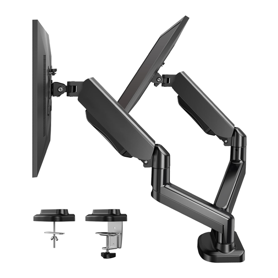
Page 3: Product Features
Product Features 270° 270° 360° 360° 180° 180° 270° 270° 360° 360° 360° +90°/-45° 180° 180° C-Clamp Mounting for table edge 0.39-3.15″ (10-80mm) Grommet Mounting for grommet bolt 0.39-2.56″ (10-65mm) - Page 4 TENSION ADJUSTMENT SHOULD ONLY BE PERFORMED AFTER MONITOR INSTALLATION Attention DO NOT adjust tension without monitor attached. 1. Verify the weight of your monitor (including accessories) is within 2-10kg (4.4-22 lbs). 2. Monitor weight can be found in manual or on manufacturer's website. 3.
- Page 5 Technical Support at 1-800-556-0533 (US/CA), 44-808-196-3874 (UK) or Customer Service at support@huanuo.com. • NOTE: Not all hardware included in this package will be used. Supplied Parts and Hardware List M4 ×...
-
Page 6: Step 1 Install The Base
Step 1 Install the Base Option A: For Clamp Mounting Compatible desk thickness: 0.39''-3.15'' (10-80mm) Desk... - Page 7 Desk Option B: For Grommet Mounting Compatible desk thickness: 0.39-2.56″ (10-65mm) Desk B-2 Remove the lock plate [06a] and keep it for use in Step B-3.
- Page 8 WARNING: Ensure the bolt and nut are securely tightened. NOTE: If a hole is needed for grommet installation, be 7/16-7/8 ″ sure to leave at least 2″ (50mm) from the edge of (11-22mm) desktop and mark where the hole will be drilled. Use Drill Drill Bit either a 7/16-7/8″...
- Page 9 Step 2 Secure the Arms to the Base 2-1 Push the extension arms [02] into the base, and then tighten the set screws on the arm joints. NOTE: The cable management cover face down. Desk 2-2 Slide the compression arms [01] onto the extension arms [02], and then tighten the set screws.
- Page 10 Step 3 Attach the Monitor Plates to the Monitors 3-1 Select Monitor Bolts M4 x 30mm M4 x 12mm Hand thread bolts into the threaded inserts on the back of your monitor to determine which bolt (M4 x 12mm or M4 x 30mm ) to use. A minimum of 4-5 turns into the threading is required. Do not turn past the bottom of the hole.
- Page 11 Step 4 Attach the Monitors to the Mount Loosen the knobs [S] on the compression arms, and slide the monitor plates [04] downways onto the ends of the arms. Tighten the knobs [S] to fasten the monitors. HEAVY! You may need assistance with this step.
- Page 12 Step 5 Adjust the Gas Spring Tension 5-1 Carefully press down on the compression arm so that it is level with the desk. (This may require more force than you think. Ask for help if needed). In this position, you can access the adjustment screw to increase or decrease the tension to balance the arm.
-
Page 13: Step 7 Tilt Adjustment
Step 6 Rotation Restriction To ensure proper stability, do not position monitor behind base. Monitor and arms should remain over the desktop. Failure to do so may cause instability, resulting in property damage or injury. Incorrect orientation Correct orientation Step 7 Tilt Adjustment The monitor should adjust easily when moved, then stay in place. -
Page 14: Step 8 Rotation Adjustment
Step 8 Rotation Adjustment WARNING: Ensure the monitor bolts and bolts securing the monitors to the mount are fully tightened before rotation. t a t i o t a t i o ° R o ° R o 3 6 0 3 6 0 Desk... - Page 15 Step 9 Route Cables Along the Arm Desk...
- Page 16 Si le motif VESA de votre moniteur est inférieur à 75 x 75mm / 3 x 3 po ou supérieur à 100 x 100mm / 3,9 x 3,9 po, ce support n'est PAS COMPATIBLE avec votre moniteur. Veuillez contacter notre service client à support@huanuo.com pour trouver un produit compatible.
-
Page 17: Caractéristiques Du Produit
Caractéristiques du produit 270° 270° 360° 360° 180° 180° 270° 270° 360° 360° 360° +90°/-45° 180° 180° Montage à l'pince de serrage en C 10 à 80mm (0,39-3,15 po) Montage à l'aide d'un passe-fil 10 à 65mm (0,39-2,56 po) - Page 18 LE REGLAGE DES TENSIONS NE DOIT ETRE EFFECTUE QU’APRES L’INSTALLATION DU MONTAGE ATTENTION NE PAS régler la tension sans moniteur attaché. 1. Vérifiez que le poids de votre moniteur (y compris les accessoires) est compris entre 4,4–22 livres (2–10kg). 2. Les informations sur le poids du moniteur se trouvent dans sa boîte ou dans son manuel.
- Page 19 N'utilisez pas de pièces endommagées ou défectueuses. Si vous avez besoin de pièces de rechange, veuillez contacter notre ligne d'assistance technique au 1-800-556-0533 (US/CA) / 44-808-196-3874 (UK) ou le service client à support@huanuo.com. • VEUILLEZ NOTER : le matériel inclus dans cet ensemble ne sera pas utilisé en totalité.
-
Page 20: Étape 1 Installation De La Base
Étape 1 Installation de la base Option A : Pour le montage du collier de serrage Épaisseur de bureau compatible : 10 à 80mm Bureau (0.39 po-3.15 po) - Page 21 Bureau Option B : Pour le montage des passe-fils Épaisseur de bureau compatible : 10 à 65mm Bureau (0.39-2.56 po) B-2 Retirez la plaque de verrouillage [06a] et conservez-la pour l'utiliser à l'étape B-3.
- Page 22 AVERTISSEMENT : Assurez-vous que le boulon et l'écrou sont bien serrés. REMARQUE : Si un trou est nécessaire pour l'installation du 11 à 22mm passe-fil, veillez à laisser au moins 50mm (2 po) du bord du (7/16-7/8 po ) bureau et marquez l'endroit où le trou sera percé. Utilisez Foreuse Mèche à...
- Page 23 Étape 2 Fixez les bras à la base 2-1 Insérez les bras d'extension [02] dans la base, puis serrez les vis de blocage sur les articulations des bras. REMARQUE : Le couvercle de gestion des câbles doit être orienté vers le bas. Bureau 2-2 Faites glisser les bras de compression [01] sur les bras d'extension [02], puis serrez les vis de blocage.
- Page 24 Étape 3 Montage des plaques du moniteur sur le moniteur 3-1 Sélectionnez les boulons du moniteur M4 x 30mm M4 x 12mm Enfilez à la main les boulons dans les inserts filetés à l'arrière de votre moniteur pour déterminer le boulon à...
- Page 25 Étape 4 Fixer les moniteurs au support Desserrez les boutons [S] sur les bras de compression, et faites glisser les plaques de moniteur [04] vers le bas sur les extrémités des bras. Serrez les boutons [S] pour fixer les moniteurs. LOURD ! Vous aurez peut-être besoin d'aide pour cette étape.
- Page 26 Étape 5 Réglage de la tension du ressort à gaz 5-1 Appuyez délicatement sur le bras de compression pour qu'il soit de niveau avec le bureau. (Cela peut nécessiter plus de force que vous ne le pensez. Demandez de l'aide si nécessaire).
-
Page 27: Étape 7 Réglage De L'inclinaison
Étape 6 Restriction de rotation Pour assurer une bonne stabilité, ne placez pas le moniteur derrière la base. Le moniteur et les bras doivent rester au-dessus du bureau. Le non-respect de cette consigne peut provoquer une instabilité et entraîner des dommages matériels ou des blessures. Orientation incorrecte Orientation correcte Étape 7 Réglage de l'inclinaison... -
Page 28: Étape 8 Réglage De La Rotation
Étape 8 Réglage de la rotation AVERTISSEMENT : Assurez-vous que les boulons du moniteur et les boulons fixant les moniteurs au support sont bien serrés avant la rotation. 6 0 ° 6 0 ° d e 3 d e 3 t i o n t i o n R o t a... - Page 29 Étape 9 Acheminement des câbles le long du bras Bureau...
- Page 31 HUANUO offers products in these categories Monitor Stands Laptop Tables Lap Desks Desktop Converters Desk Mounts TV Trays Printer Stands Stand Risers Please remember us when you need one.
- Page 32 (US / CA) 1-800-556-0533 (UK) 44-808-196-3874 support@huanuo.com WWW. www.huanuo.com 860-00836-00 Rev00...
Need help?
Do you have a question about the HNDSK4 and is the answer not in the manual?
Questions and answers