
Related Manuals for VGP OSSC Pro

Summary of Contents for VGP OSSC Pro
- Page 1 OSSC Pro Quick Start Guide This document is copyright © VGP Media Ltd 2023 All rights reserved worldwide VideoGameperfection.com is a trading name of VGP Media Ltd Registered in Republic of Ireland number 637539...
-
Page 2: Table Of Contents
Fine tuning the image........................16 Audio input and output......................16 Firmware updates...........................17 Troubleshooting..........................18 More information........................19 Disposing of your OSSC Pro......................19 Thank you for purchasing the OSSC Pro. Please take time to read through this short document before you start using the unit. Page 2... -
Page 3: Important Safety Information
Please observe the following safety precautions when using your OSSC Pro. Use the correct power supply – OSSC Pro is designed to run with a 5 volt, 2.1 x 5.5mm positive tip power supply unit (PSU) supplying at least 2.5 amps of current. Please ensure your power supply meets these requirements. -
Page 4: Overview
Status LEDs – Indicate various functions of the OSSC Pro. The top most LED will illuminate Red when the OSSC Pro is in standby (all other LEDs will be off). A Red and Green LED illuminated together indicates an error condition with the current input. The middle LED will also blink when an IR command is received. -
Page 5: Connectors (Left Side)
Connectors (left side) Expansion Connector – For adding expansion boards to the OSSC Pro. Expansion boards can add new functionality and input and output options. Connectors (Right side) JTAG Connector - For software development purposes and firmware updates. AV1 (SCART) Input – Connect an RGB SCART source to this input. Note the input must be RGB or YPbPr, S-video and composite SCART sources are not supported and require transcoding into RGB first. -
Page 6: Connectors (Back)
Power Connector – Connect a 5 volt, 2.1 x 5.5mm positive tip power supply unit (PSU) supplying at least 2.5 amps of current. Note that use of the OSSC Classic power supply is not recommended as it does not provide sufficient amps for the OSSC Pro. Page 6... -
Page 7: Remote Control
Remote control The OSSC Pro uses a new, larger remote control to control all of its functions. We will cover the most important functions in this guide, while you can learn about other features by visiting the OSSC Pro Wiki page (https://junkerhq.net/xrgb/index.php?title=OSSC_Pro). -
Page 8: Connecting Your Ossc Pro
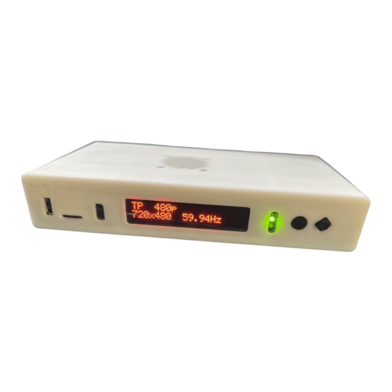
Ensure the PSU is turned on at the wall, the red Standby light should then illuminate on the front of the unit. Power on your OSSC Pro using the power button on the remote control or by holding the menu button on the front of the unit. The OLED display on the front of the unit should light up and display “TP 480p”, as shown in the picture. - Page 9 “AV2_YpbPr”. VGA sources, such as a Sega Dreamcast, require “AV3_RGBHV”. For digital video sources, choose “AV4”. You should now see a picture from your video device. Congratulations, you have now set up your OSSC Pro and you can start experimenting with its features.
-
Page 10: Getting To Know Your Ossc Pro
Getting to know your OSSC Pro All settings for the OSSC Pro are configured using the on-screen menu. To call up the menu at any time, press the Menu button on the remote. The root or top level menu is shown below. - Page 11 Scaler - no Pure LM Adaptive LM Scaler – framelock framelock Latency Max 2 lines Max 60 lines ~1 frame 1-2 frames Display Variable Very high Very high Full compatibility Bob, Bob, Bob, Weave, Motion Bob, Weave, Deinterlace alg. Noninterlace Noninterlace adaptive Motion adaptive...
-
Page 12: Changing Modes
Connecting consoles, PCBs or other hardware Power your OSSC Pro off before you connect or disconnect external hardware. For the best results, always use the best quality connection from your source device to your OSSC Pro. For most vintage or retro systems, using a properly wired RGB SCART cable connected to the AV1 input is the best and easiest option. -
Page 13: Scanlines
CRT that were a result of this screen mode. OSSC Pro allows you to simulate these scanlines, making the image look more authentic. You can enable or disable post-processing scanlines on the OSSC Pro by pressing the Menu button on the remote and navigating to “Scanline... - Page 14 If the OSSC Pro is set to scaler mode, the range of output resolutions is more flexible. Again, some experimentation may be required to find the best looking or most compatible modes for your display.
-
Page 15: Framelock
These modes send alternating scanlines to the display in each frame and were how standard definition analogue television was broadcast. To display interlace video on modern displays, it must be deinterlaced first. In line multiplication mode, the OSSC Pro can deinterlace content like this with no input lag. -
Page 16: Fine Tuning The Image
Audio input and output The OSSC Pro’s analogue audio inputs and the SPDIF input are all fully assignable. For example, if you have a source such as a Sega Dreamcast, which has a D-Sub 15 video output and 2 x RCA audio outputs, you can connect the video output of the console to the AV3 input, and the audio to the AV2 RCA audio inputs. -
Page 17: Firmware Updates
SD card reader and then copy over the new firmware file. Ensure that the firmware file is renamed to “ossc_pro.bin”. Once the firmware is copied over, re-insert the MicroSD card into the OSSC Pro and power on the device. Open the on-screen menu and choose “Settings” and then “Fw. Update”. Follow the on- screen prompts in order to update the firmware. -
Page 18: Troubleshooting
OSSC Pro Quick Start Guide VideoGamePerfection.com Troubleshooting Symptom Possible Cause Solution Image has a vertical flicker/shimmer Interlace source connected Set deinterlace mode to motion effect adaptive, see page 15. Horizontal jitter/wobble on image Fine tuning required Try adjusting low pass filter settings. -
Page 19: More Information
More information For more information on using your OSSC Pro, see the Wiki page here – https://junkerhq.net//xrgb/index.php?title=OSSC Pro For technical support, visit the support forums here - https://www.videogameperfection.com/forums/forum/ossc/ Disposing of your OSSC Pro If your OSSC Pro malfunctions, please contact us via e-mail or through our website to arrange repair or replacement.
Need help?
Do you have a question about the OSSC Pro and is the answer not in the manual?
Questions and answers