
Related Manuals for SpeedyBee F7 V3 BL32 50A 30x30 Stack

Summary of Contents for SpeedyBee F7 V3 BL32 50A 30x30 Stack
-
Page 1: Table Of Contents
User Manual SpeedyBee F7 V3 BL32 50A 30x30 Stack contents Part 1 - OverView Specs Overview Dimensions Package FC & ESC Connection Part 2 - SpeedyBee F7 V3 Flight Controller Layout FC’s Peripheral Connection FC Firmware Update Specifications Part 3 - SpeedyBee BL32 50A 4-in-1 ESC Layout Connection with Motors &... -
Page 2: Part 1 - Overview
Part 1 - OverView Specs Overview 1/13 SpeedyBee F7 V3 BL32 50A 30x30 Stack Product Name SpeedyBee F7 V3 Flight Controller SpeedyBee BL32 50A 4-in-1 ESC Supported. For FC & ESC parameter setting Bluetooth Supported Wireless FC Firmware Flashing Supported... -
Page 3: Dimensions
Dimensions 2/13 1.6mm 38mm 1.6mm 40mm 8.1mm 30.5mm 8.8mm 30.5mm 1.7mm 16.1mm... -
Page 4: Package
Package 3/13 SpeedyBee F7 V3 Flight Controller x 1 SpeedyBee BL32 50A 4-in-1 ESC x 1 DJI 6pin Cable(80mm) x 1 SH 1.0mm 15mm-length 8pin Cable(for FC-ESC connection) x 1 M3*8mm Silicone Grommets(for FC) x 5 M3*8.1mm Silicone Grommets(for ESC) x 5... -
Page 5: Fc & Esc Connection
FC & ESC Connection 4/13 Method 1 - Direct Soldering CURRENT VBAT F7 V3 Flight Controller BL32 50A 4-in-1 ESC Method 2 - All connectors F7 V3 Flight Controller BL32 50A 4-in-1 ESC... -
Page 6: Part 2 - Speedybee F7 V3 Flight Controller Layout
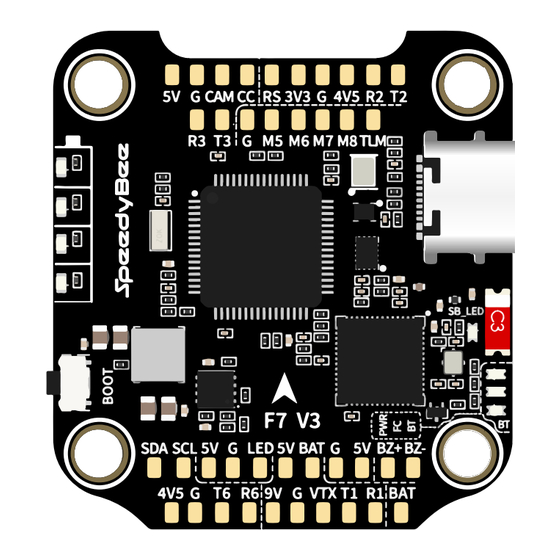
Part 2 - SpeedyBee F7 V3 Flight Controller Layout 5/13 Receiver For Second 4-in-1 ESC FPV Cam(Analog) Barometer(BMP280) MCU: F722 USB TYPC-C Port 4-level LED battey indicator Antenna Orange LED RED LED BOOT Button BLUE LED GREEN LED 5V 2A BEC Bluetooth/WiFi Chip GPS&Compass... -
Page 7: Fc's Peripheral Connection
FC’s Peripheral Connection 6/13 Wiring Diagram Method 1 - Direct Soldering Spektrum SRXL2 Receiver Receiver SBUS Crossfire Nano Rx CH2 RX CH1 TX Video Camera LED Strip Buzzer 7.4-26.4V DJI Air Unit SBUS Video VIDEO PGND 3.7-5V... - Page 8 Method 2 - All connectors To recognize the wires in the package better, we marked some of these wires with letters(from A to F). Please find the right wires accroding to their letters. Cable A(3cm) or B(6cm) Crossfire Nano Rx FPV Cam V IRC G 5V Analog VTX...
- Page 9 Importance notice for SBUS receiver When using an SBUS receiver, the SBUS signal wire of the receiver must be connected to the SBUS pad on the front side of the flight controller (this pad internally uses UART2). If you are also using the DJI Air Unit(O3/Link/Vista/Air Unit V1), you will need to disconnect the SBUS signal wire from the Air Unit harness.
- Page 10 Cable Connection vs DJI O3 Air Unit Use 6-pin cable comes with the O3 Air Unit Cable Connection vs RunCam Link/ Caddx Vista Air Unit Use 6-pin cable comes with the F7 V3 stack (See the accessory No.3 in the package section) SBUS 7.4-26.4V Cable Connection vs DJI Air Unit V1...
- Page 11 Receiver 8pin Connector (to ESC) FPV Camera LED2 LED4 LED2 LED4 LED1 LED3 LED1 LED3 Analog VTX(5V) DJI Air Unit...
-
Page 12: App
7/13 Get the SpeedyBee App Search ‘SpeedyBee’ on Google Play or App Store. Or download the Android .apk file on our website: https://www.speedybee.com/download Connect the App... -
Page 13: Fc Firmware Update
FC Firmware Update 8/13... -
Page 14: Specifications
LED strips connected to LED1-LED4 connectors on the bottom side. By default, short-press the BOOT button to cycle the LED displaying mode. Long- press the BOOT button to switch between SpeedyBee-LED mode and BF-LED mode. Under BF-LED mode, all the LED1-LED4 strips will be controlled by Betaflight firmware. -
Page 15: Part 3 - Speedybee Bl32 50A 4-In-1 Esc Layout
Part 3 - SpeedyBee BL32 50A 4-in-1 ESC Layout 10/13 MOTOR 4 MOTOR 2 MOTOR 3 MOTOR 1 CNC Heat Sink Capacitor pin Capacitor pin BAT- BAT+ hole(GND) hole(BAT+) 8pin connector(to FC) Driver chips F4 MCUs TVS Diode Power Inductor... -
Page 16: Connection With Motors & Power Cable
Connection with Motors & Power Cable 11/13 Motor 4 Motor 2 Motor 3 Motor 1 1000uF Low ESR Capacitor XT60 Power Cable Note: In order to prevent the stack from being burnt out instantaneous voltage spikes on powering up, it is strongly recommended to use the Low ESR capacitor in the package. -
Page 17: Esc Conifguration & Firmware Update
This ESC is a 32-bit ESC running BLHeli32 firmware inside. Since the BLHeli32 is close-sourced. So ESC configuration & firmware update can't be done wirelessly in the SpeedyBee app. Please download the latest BLHeliSuit32 configurator to setup your ESC at https://github.com/bitdump/BLHeli/releases. -
Page 18: Specifications
Specifications 13/13 Product Name SpeedyBee BL32 50A 4-in-1 ESC Firmware J-H-50 Configurator Download Link http://github.com/bitdump/BLHeli/releases Continuous Current 50A * 4 Burst Current 55A(5seconds) TVS Protective diode Heat Sink External Capacitor 1000uF Low ESR Capacitor(In the package) ESC Protocol DSHOT300/600 PWM Frequency Range...
Need help?
Do you have a question about the F7 V3 BL32 50A 30x30 Stack and is the answer not in the manual?
Questions and answers