Table of Contents
Advertisement
Quick Links
CAUTION ............................................................................................................................. INSIDE COVER
GENERAL IMPORTANT INFORMATION .................................................................................................. 1
SERVICING ................................................................................................................................................ 2
CAUTION, MICROWAVE RADIATION, WARNING ................................................................................... 5
PRODUCT SPECIFICATIONS ................................................................................................................... 5
APPEARANCE VIEW ................................................................................................................................. 6
OPERATION SEQUENCE .......................................................................................................................... 7
FUNCTION OF IMPORTANT COMPONENTS .......................................................................................... 8
TEST PROCEDURES .............................................................................................................................. 10
TOUCH CONTROL ASSEMBLY .............................................................................................................. 19
COMPONENT REPLACEMENT AND ADJUSTMENT PROCEDURE ..................................................... 23
TEST DATA AT A GLANCE ..................................................................................................................... 27
MICROWAVE MEASUREMENT .............................................................................................................. 28
WIRING DIAGRAMS ................................................................................................................................ 29
SWITCH UNIT CIRCUIT ............................................................................................................................32
PICTORIAL DIAGRAM ..............................................................................................................................33
PRINTED WIRING BOARD OF SWITCH UNIT ........................................................................................34
PARTS LIST ............................................................................................................................................. 35
EXPLODED VIEW OF OVEN .................................................................................................................... 38
CONTROL PANEL & DOOR PARTS ........................................................................................................ 39
MISCELLANEOUS/PACKING AND ACCESSORIES ............................................................................... 40
SERVICE MANUAL
R
COOK
DEFR OST
MODELS
R-363
R-363(IN)
In interests of user-safety the oven should be restored to its original
condition and only parts identical to those specified should be used.
TABLE OF CONTENTS
SHARP CORPORATION
S06278R363EHW
MICROWAVE OVEN
R-363(IN)
Page
Advertisement
Table of Contents

Related Manuals for Sharp R-363(IN)


Summary of Contents for Sharp R-363(IN)
-
Page 1: Table Of Contents
WIRING DIAGRAMS ..........................29 SWITCH UNIT CIRCUIT ..........................32 PICTORIAL DIAGRAM ..........................33 PRINTED WIRING BOARD OF SWITCH UNIT ..................34 PARTS LIST ............................. 35 EXPLODED VIEW OF OVEN ........................38 CONTROL PANEL & DOOR PARTS ......................39 MISCELLANEOUS/PACKING AND ACCESSORIES ................40 SHARP CORPORATION... -
Page 2: General Important Information
R-363(IN) GENERAL IMPORTANT INFORMATION This Manual has been prepared to provide Sharp Corp. Service engineers with Operation and Service Information. It is recommended that service engineers carefully study the entire text of this manual, so they will be qualified to render satisfactory customer service. -
Page 3: Servicing
HIGH en stelt de klok van de magnetron in op Sharp beveelt ten sterkste aan dat, voor zover twee (2) minuten. Wanneer de twee minuten voorbij... - Page 4 Sharp rekommenderar att felsökning sker med När all service är klar och ugnen ihopskruvad skall strömmen fränkopplad. Ibland kan det var nödvändigt ugnens uteffekt och eventuellt mikrovågsläckage att koppla på...
- Page 5 è rimasta fredda, eseguire i tre controlli iniziali e verificare nuovamente i collegamenti del componente in Sharp raccomanda, nei limiti del possibile, che la ricerca questione. dei guasti avvenga in assenza di alimentazione elettrica. In alcuni casi tuttavia, può essere necessario alimentare Dopo aver portato a termine le operazioni di manutenzione l'apparecchio dopo aver rimosso la scatola esterna.
-
Page 6: Caution, Microwave Radiation, Warning
CAUTION/WARNING CAUTION WARNING MICROWAVE RADIATION Servicing and repair work must be carried out only by trained service engineers. Service engineers should not be exposed to the All the parts marked "*" on parts list are used at microwave energy which may radiate from the voltages more than 250V. -
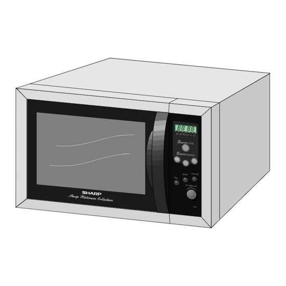
Page 7: Appearance View
APPEARANCE VIEW OVEN TURNTABLE Door Door hinges Oven lamp Waveguide cover Contol panel Coupling ROLLER STAY Door latches Oven cavity COUPLING Door seals and sealing surfaces 10. Safety door latches 11. Door handle 12. Ventilation openings 13. Outer case 14. Rear back plate 1. -
Page 8: Operation Sequence
OPERATING SEQUENCE OFF CONDITION CONDITION Closing the door activates all door interlock switches DURING DOOR OPEN (monitored latch switch and stop switch). SWITCH CONTACT COOKING (NO COOKING) Monitored latch switch COM-NO Closed Open IMPORTANT Monitor switch COM-NC Open Closed When the oven door is closed, the monitor switch contacts COM-NO Closed Open... -
Page 9: Function Of Important Components
FUNCTION OF IMPORTANT COMPONENTS FUSE F1 F8A 250V 1. If the wire harness or electrical components are short- DOOR OPEN MECHANISM circuited, this fuse blows to prevent an electric shock or The door can be opened by puiiing the door handle. When fire hazard. - Page 10 FUNCTION OF IMPORTANT COMPONENTS The rated peak reverse voltage of D1 of the asymmetric ASYMMETRIC RECTIFIER rectifier is 6 KV. The rated peak reverse voltage of D2 of the The asymmetric rectifier is a solid state device that prevents asymmetric rectifier is 1.7 KV. D1 and D2 of the asymmetric current flow in both directions.
-
Page 11: Test Procedures
TEST PROCEDURES TEST PROCEDURE POSSIBLE CAUSE DEFECTIVE PARTS PROBLEM CONDITION Home fuse blows when power cord is plugged into wall outlet. Fuse F8A blows when the door is opened. Special fuse blows when power supply cord is plugged into wall outlet. “88:88”... - Page 12 TEST PROCEDURES R-363 -...
- Page 13 TEST PROCEDURES PROCEDURE LETTER COMPONENT TEST MAGNETRON TEST NEVER TOUCH ANY PART IN THE CIRCUIT WITH YOUR HAND OR AN INSULATED TOOL WHILE THE OVEN IS IN OPERATION. CARRY OUT 3D CHECK Isolate the magnetron from high voltage circuit by removing all leads connected to filament terminal. To test for an open circuit filament use an ohmmeter to make a continuity test between the magnetron filament terminals, the meter should show a reading of less than 1 ohm.
- Page 14 TEST PROCEDURES PROCEDURE LETTER COMPONENT TEST 6. Measure the final water temperature. (Example: The final temperature T2 = 21°C) 7. Calculate the microwave power output P in watts from above formula. Initial temperature ......................T1 = 11°C Temperature after (47 + 3) = 50 sec................T2 = 21°C Temperature difference Cold-Warm ................
- Page 15 TEST PROCEDURES PROCEDURE LETTER COMPONENT TEST ASYMMETRIC ASYMMETRIC RECTIFIER TEST RECTIFIER HIGH VOLTAGE RECTIFIER CARRY OUT 3D CHECKS. Isolate the high voltage rectifier assembly from the HV circuit. The asymmetric rectifier can be tested using an ohmmeter set to its highest range. Connect the ohmmeter across the terminals A + B of the asymmetric rectifier and note the reading obtained.
- Page 16 TEST PROCEDURES PROCEDURE LETTER COMPONENT TEST THERMAL CUT OUT TEST CARRY OUT 3D CHECKS Disconnect the leads from the terminals of the thermal cut-out. Then using an ohmmeter, make a continuity test across the two terminals as described below. CARRY OUT 4R CHECKS Temperature of ”ON”...
- Page 17 TEST PROCEDURES PROCEDURE COMPONENT TEST LETTER MOTOR WINDING TEST CARRY OUT 3D CHECKS Disconnect the leads from the motor. Using an ohmmeter, check the resistance between the two terminals as described in the table below. Table: Resistance of Motor Motors Resistance Fan motor Approximately 290Ω...
- Page 18 TEST PROCEDURES PROCEDURE COMPONENT TEST LETTER CN - C SWITCH UNIT TEST If the display fails to clear when the STOP key is de- pressed, first verify the lead wire harness is making good contact, verify that the door sensing switch (stop switch) operates properly;...
- Page 19 TEST PROCEDURES PROCEDURE COMPONENT TEST LETTER PROCEDURES TO BE TAKEN WHEN THE FOIL PATTERN ON THE PRINTED WIRING BOARD (PWB) IS OPEN To protect the electronic circuits, this model is provided with a fine foil pattern added to the input circuit on the PWB, this foil pattern acts as a fuse.
-
Page 20: Touch Control Assembly
TOUCH CONTROL PANEL ASSEMBLY OUTLINE OF TOUCH CONTROL PANEL The touch control section consists of the following units. 4) Relay Circuit To drive the magnetron, fan motor, turntable motor and (1) Switch Unit light the oven lamp. (2) Control Unit 5) Buzzer Circuit The principal functions of these units and the signals commu- The buzzer is responsive to signals from the LSI to emit... - Page 21 DESCRIPTION OF LSI LSI(IXA027DR) The I/O signal of the LSI(IXA027DR) are detailed in the following table. Pin No. Signal Description 1-12 SEG0 - Segment data signal. SEG11 Connected to LCD. The relation between signals are as follows: LSI signal (Pin No.) LCD (Pin No.) LSI signal (Pin No.) LCD (Pin No.)
- Page 22 DESCRIPTION OF LSI Pin No. Signal Description INT2 Signal synchronized with commercial power source frequency. This is the basic timing for time processing of LSI. H : +5V L : 0V 20.0 msec Signal coming from tact switch. When either of tact switches SW5-SW6 is touched, a corresponding signal out of R60, R61, R62 and R63 will be input into R81.
- Page 23 TOUCH CONTROL 1. Precautions for Handling Electronic Components panel while keeping it connected to the oven. This unit uses CMOS LSI in the integral part of the B. On some models, the power supply cord between circuits. When handling these parts, the following the touch control panel and the oven proper is so precautions should be strictly followed.
-
Page 24: Component Replacement And Adjustment Procedure
COMPONENT REPLACEMENT AND ADJUSTMENT PROCEDURE WARNING: Avoid possible exposure to microwave energy. Please follow the instructions below before operating the oven. 1. Door does not close firmly. 1. CARRY OUT 3D CHECKS. 2. Make sure that a definite "click" can be heard when the 2. - Page 25 6. After replacement use the one (1) screw provided with 3. Where the corners have been snipped off bend corner the turntable motor assembly to fit the turntable motor areas flat. No sharp edge must be evident after removal cover. of TT motor cover.
- Page 26 COMPONENT REPLACEMENT AND ADJUSTMENT PROCEDURE PRIMARY LATCH SWITCH, STOP SWITCH AND MONITOR SWITCH REMOVAL 1. CARRY OUT 3D CHECKS. 2. Remove the control panel assembly referring to Stop switch “CONTROL PANEL REMOVAL”. 3. Disconnect the leads from all switches. 4. Remove the two (2) screws holding the latch hook to the oven cavity.
- Page 27 COMPONENT REPLACEMENT AND ADJUSTMENT PROCEDURE DOOR REPLACEMENT 3. Re-install the latch spring to the latch head. Re-install REMOVAL the latch spring to the door frame. Re-install latch 1. CARRY OUT 3D CHECKS. head to door frame. 2. Pull door handle to open door. 4.
-
Page 28: Test Data At A Glance
(Magnetron, high voltage transformer, high voltage capacitor and high voltage rectifier assembly) Parts that become hot. (Heating elements, oven lamp, oven cavity magnetron and high voltage transformer) Sharp edges. (Bottom plates, oven cavity, waveguide flange, chassis support and other metallic parts) Movable parts. -
Page 29: Microwave Measurement
MICROWAVE MEASUREMENT After adjustment of door latch switches, monitor switch and Recommended instruments are: door are completed individually or collectively, the following NARDA 8100 leakage test must be performed with a survey instrument NARDA 8200 and it must be confirmed that the result meets the HOLADAY HI 1500 requirements of the performance standard for microwave SIMPSON 380M... -
Page 30: Wiring Diagrams
230V ~ 50HZ 230V ~ 50HZ BLU / 17 BRN / 17 BLU / 17 BRN / 17 G-Y / 17 FUSE G-Y / 17 EARTH FUSE EARTH NOISE SUPPRESSION COIL NOISE SUPPRESSION COIL NOISE FILTER NOISE O. 22 F / 250V UNIT FILTER O. - Page 31 NEUTRAL LIVE TC2: OVEN EARTH NOISE THERMAL POWER CUT-OUT FILTER SUPPLY UNIT CORD TOUCH CONTROL PANEL SW2: MONITOR SWITCH SW1: MONITORED LATCH SWITCH TC1: MAGNETRON THERMAL CUT-OUT MOTOR OL: OVEN LAMP CN-B CN-A RLY 2 MG: MAGNETRON TTM: TURNTABLE MOTOR SHORT PROTECTOR SW3:...
- Page 32 LIQUID CRYSTAL DISPLAY NOTE : : IF NOT SPECIFIED 1/4W – 5% : IF NOT SPECIFIED 1SS270A CN-C : IF NOT SPECIFIED 0.01 F/16V CN-C CN - C CN-C CN-C CN-C CN-C D1 R1 R2 R3 R4 R10 27k R11 27k R1-5 1N4005E 1k x 5 2w...
-
Page 33: Switch Unit Circuit
SWITCH UNIT CIRCUIT CN - C Figure S-3. Switch Unit Circuit R-363 -... -
Page 34: Pictorial Diagram
WARNING: AC LINE VOLTAGE IS SUPPLIED TO ALL PARTS VRS1 SP30 ZD70 ZD40 (CF1) (C60) (C61) (R65) ZD20 CN - B ZD21 (R64) (SW60) (JSW2) WARNING: (WH-1) TRANSLESS (SW1) (SW2) (SW3) (SW4) (SW5) (SW6) (SW7) -
Page 35: Printed Wiring Board Of Switch Unit
PRINTED WIRING BOARD OF SWITCH UNIT Figure S-5. Printed Wiring Board of Switch Unit R-363 -... -
Page 36: Parts List
PARTS LIST Note: The parts marked “*” are used in voltage more than 250V. The parts marked "∆" may cause undue microwave exposure “§” MARK: SPARE PARTS-DELIVERY SECTION REF. NO. PART NO. § Q’TY CODE DESCRIPTION ELECTRIC PARTS ∆ ∆ RV-MZA264WRE0 U Magnetron RC-QZA222WRE0... - Page 37 PARTS LIST Note: The parts marked ”*” are used in voltage more than 250V. The parts marked "∆" may cause undue microwave exposure “§” MARK: SPARE PARTS-DELIVERY SECTION REF. NO. PART NO. § Q’TY CODE DESCRIPTION CONTROL PANEL PARTS CONTINUED VRD-B12EF822J U Resistor 8.2k ohm...
- Page 38 PARTS LIST Note : The parts marked “*” are used in voltage more than 250V. The parts marked "∆" may cause undue microwave exposure “§” MARK: SPARE PARTS-DELIVERY SECTION REF. NO. PART NO. § Q’TY CODE DESCRIPTION DOOR PARTS ∆ FDORFA287WRT0 U Door panel sub assembly ∆...
-
Page 39: Exploded View Of Oven
EXPLODED VIEW OF OVEN CABINET AND UNIT CHASSIS PARTS 7-10 7-10 7-10 7-10 6-11 4-12 4-13 4-14 7-10 4-16 7-11 4.17 NOTE: In the event of removing the turntable motor cover this part should be refitted using screw connection: LX-EZA045WRE0(7-11) R-363 -... -
Page 40: Control Panel/Door Parts
CONTROL PANEL/DOOR PARTS 3 - 1 CONTROL PANEL PARTS 3-1E 3-1F 3-1D 3-10 3 - 2 3-10 3 - 6 3 - 3 3 - 5 3 - 9 3 - 4 3 - 7 3 - 8 DOOR PARTS 5-10 R-363 -... -
Page 41: Miscellaneous/Packing And Accessories
MISCELLANEOUS/PACKING AND ACCESSORIES MISCELLANEOUS Actual wire harness may be different from illustration. PACKING AND ACCESSORIES PACKING KIT CPADBA146WRK0 DOOR PROTECTION SHEET SPADPA020WRE0 POLYETHENE BAG SSAKHA041WRE0 ROLLER STAY MICROWAVE OVEN INTO THE OVEN CAVITY (DIAGONALLY) TRAY PACK SPADPA015URE0 TURNTABLE TRAY INTO THE OVEN CAVITY PACKING CASE TRAY PACK... - Page 42 NOTES R-363 -...
- Page 43 COPYRIGHT C 2000 BY SHARP CORPORATION ALL RIGHT RESERVED. No part of this publication may be reproduced, stored in a retrieval system, or transmitted in any form or by any means, electronic, mechanical, photocopying, recording, or otherwise, without prior written permission of the publisher.
- Page 44 CAUTION MICROWAVE RADIATION Personnel should not be exposed to the mircowave energy which may radiate from the magnetron or other microwave generating devices if it is improperly used or connected. All input and output micro- wave connections, waveguides, flanges and gaskets must be secured. Never operate the device with- out a microwave energy absorbing load attached.