Table of Contents
Advertisement
Quick Links
PRODUCT MANUAL
Truck Wheel Balancer
With pneumatic lift platform
MODEL:TMG-TWB24
Please read the product manual completely before assembly
Check against the parts list to make sure all parts are received
Wear proper safety goggles or other protective gears while in assembly
Missing parts or questions on assembly?
Please call: 1-877-761-2819 or email: cs@tmgindustrial.com
Do not return the product to dealer, they are not equipped to handle your
requests
WWW.TMGINDUSTRIAL.COM
Toll Free:1-877-761-2819
Advertisement
Table of Contents

Subscribe to Our Youtube Channel
Summary of Contents for TMG TMG-TWB24
- Page 1 PRODUCT MANUAL Truck Wheel Balancer With pneumatic lift platform MODEL:TMG-TWB24 Please read the product manual completely before assembly Check against the parts list to make sure all parts are received Wear proper safety goggles or other protective gears while in assembly Missing parts or questions on assembly? Please call: 1-877-761-2819 or email: cs@tmgindustrial.com...
-
Page 2: Table Of Contents
Contents 1.Summary of the balancing machine……………………………....……...3 1.1.Brief introduction of appearance………………………………........…..3 1.2.Performance and characteristic………………………….…......……....3 1.3.Main technical parameters………………………..……...……........…..4 1.4.Operating principle……………………..……..............4 2.Balancing machine installation guide..............5 3.Use of balancing machine................6 3.1.Attention before using ..............……………………...6 3.2.Introduction of panel............……………………………….…6 3.3.Putting through the power and number input..……....……………………………..7 3.4.Select and change the unit...................……..8 3.5.Some examples about balancing...................8 3.6.Options for mode of balancing..................9... -
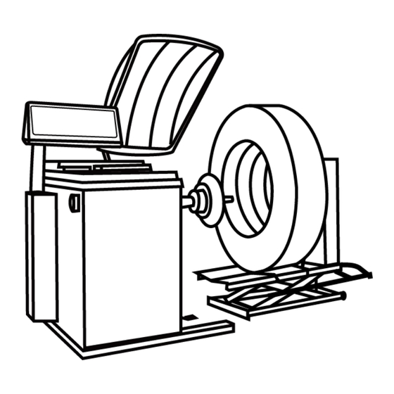
Page 3: Summary Of The Balancing Machine
1. Summary of the balancing machine 1.1.Brief introduction of appearance Wheel cover control Main box Distance finder Switch Counter Pneumatic switch Pneumatic lifting device Handle Outer air source holes in the bottom axle for balancing Protective Pedal brake 1.2. Performance and characteristic ●... -
Page 4: Main Technical Parameters
1.3. Main technical parameters Garage, transportation company , Department motorcade, The professional service station of tire Scope of application Power supply 110~120V/60Hz 1PH Machine motor 3/4HP Maximum diameter of wheel 47” Width of steel rim 5-1/2”~20” Diameter of steel rim 13”~24”... -
Page 5: Balancing Machine Installation Guide
2. Balancing machine installation guide 1. Open the package, remove the connecting screw between the balancer and the bottom bracket of the packing case, lift-off balancing machine,place it on a flat, solid ground,there should be more than 800mm space around the balancing machine for the operating convenience. -
Page 6: Use Of Balancing Machine
3. Use of balancing machine 3.1.Attention before using ※Carrying the balance machine can only lift the machine chassis , can't lift the main shaft in any case. ※Balancing machine and Pneumatic lifting device must place at steady ground (can be fixed with expansion screw ) and guarantee enough space all around or it will cause the balance error if the machine is unstable. -
Page 7: Putting Through The Power And Number Input
① indication for uneven edge inside wheel ② indication for uneven edge outside wheel ③ indication for uneven edge position inside wheel ④ indication for uneven edge position outside wheel ⑤ indication of balance mode ⑥ Data to debug key ⑦... -
Page 8: Select And Change The Unit
3.Wheel data input: Press key and choose a,pull the ruler to the inside of the rim and install the equalizer, according to the number,press key,type the actual value. This machine defaults to the common value mm。 Then press key and select input rim width data b,measure the width of two rims with the width gauge in the accessories, press key,input the width data of the caliper. -
Page 9: Options For Mode Of Balancing
3. Then rotate wheel to make outside indicator lamp be on and vertical over the main shaft, take away 115g lead lump from wheel steel (as picture) 4.At this time outside indicator also indicates 0, balance is over, unload the tire . if you test the tire again, you needn’t switch off power 3.6. - Page 10 2. ALU1-Balance the light-alloy rim, adopt a way of adhering balance lump on the two shoulders in the rim A1=A+3/4” A2=A+b-3/4” 3. ALU2-Balance the light-alloy rim, adopt a way of gluing balance lump hidden inside A1=A+3/4” A2=Point 0 the outer distance of flange-1/2” 4.
-
Page 11: Balancing Experiences
3.7.Precautions in the process of use Attention: · When power starts, push the wheel by hands to assist starting which will extend motor’s life.Due to balance angle error, please find out by yourself when this machine rotates wheel to find balance point, pay attention which direction is much more accurate when wheel turns inward or outward. -
Page 12: Self-Calibration
4.Self -calibration(Car and truck tires need to be corrected separately) Self correction has been finished in the factory. If you use for many years and change part or doubt balance to be a big error, you can self correct it again.( Choose one medium-sized tire to install on main shaft , uneventy of steel rim on both sides of wheel is relatively slight) Warning: When going self calibration, Make sure that the wheel is required to be... - Page 13 Two key elements to judge if self correction is accurate 1. Accurate number indication 2. Show that phase is right (namely outside indicator lamps are all on and 100g lead lump is rightly under shaft. ) Problems that occur after self correction: 1.Number indicated is ok, but phase is inaccurate, deviation is very great.
-
Page 14: Function Setting
5. Function setting Press key in 5 seconds , access to the following feature settings: Protection cover setting —p— On the top operation,then press key , press confirm to set B1p. electric whistle ON、OFF, press key confirm . On the top operation, press key, press key confirm to set APP. -
Page 15: Common Failure Codes And Solutions
7.Common failure codes and solutions Err—1— No counting signal, replace the computer and photo electricity board Err—2— The test speed is not enough, the spindle does not rotate the wheel Err—3— Big Measurement error, cannot calculate, replace the wheel and test again Err—4—... -
Page 16: Accessories Accompanying Machines
8.Accessories accompanying machines. A set of balancing machine and name of all accessories 1. one lead screw connecting with 5.five cones,(scope is 45mm-280mm) main shaft 2.one plastic calliper 6.one handle 3.one bags of lead lump 7.one center wheel 4.one balance pincers 8.two matching machine outside shaft W W W . -
Page 17: Exploded Drawing
EXPLODED DRAWINGS W W W . T M G I N D U S T R I A L . C O M P 1 7 / 1 9 T o l l F r e e : 1 - 8 7 7 - 7 6 1 - 2 8 1 9... - Page 18 W W W . T M G I N D U S T R I A L . C O M P 1 8 / 1 9 T o l l F r e e : 1 - 8 7 7 - 7 6 1 - 2 8 1 9...
- Page 19 W W W . T M G I N D U S T R I A L . C O M P 1 9 / 1 9 T o l l F r e e : 1 - 8 7 7 - 7 6 1 - 2 8 1 9...
Need help?
Do you have a question about the TMG-TWB24 and is the answer not in the manual?
Questions and answers
how do you get it to give weights in ounces instead of grams
@samuel lee faller
To change the TMG TWB24 to display weights in ounces instead of grams, press the unit change key. This will toggle between grams and ounces.
This answer is automatically generated