
Summary of Contents for Kurtz ERSA IR 550 A
- Page 1 Operating Instructions ERSA IR 550 A Microprocessor controlled Rework System 12682-01 ERSA GmbH Soldering Tools & Inspection Systems Division...
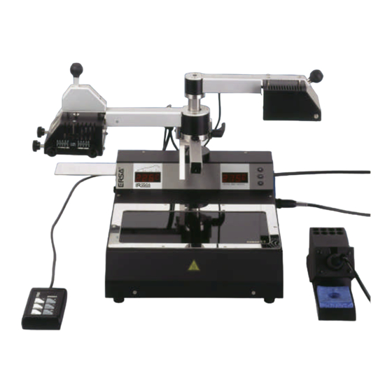
- Page 2 ERSA IR 550 A Operating instructions Pictures 1 external keypad 6 display (LED) 2 bottom radiator (glass cover) 7 infrared sensor 3 top radiator (aperture system) 8 cooling fan and laser positioning device 4 component tray 9 DIGITAL 2000 A soldering station...
- Page 3 ERSA IR 550 A Operating instructions We appreciate your decision to purchase our high-quality ERSA IR 550 A Rework System. This device has been manufactured according to highest quality standards and was tested thoroughly before shipment. It is very easy in operation, nevertheless we suggest to read this manual before operating the system.
-
Page 4: Table Of Contents
ERSA IR 550 A Operating instructions TABLE OF CONTENTS Page Introduction ..........................5 Technical Data ........................6 Safety instructions ........................7 Commissioning........................8 Before commissioning .....................8 First start-up ........................9 4.2.1 Setting up.........................9 4.2.2 Electrical connections ....................11 4.2.3 Switching on ......................11 Tips for the SMT Rework Process .................12 Functional description......................13... -
Page 5: Introduction
Operating instructions Introduction We appreciate your decision to purchase an ERSA IR 550 A Rework System. With this microprocessor unit which is also equipped with powerful infrared- an sensor technique ERSA provides a rework soldering system to meet the highest requirements of modern industrial electronic production. -
Page 6: Technical Data
ERSA IR 550 A Operating instructions Technical Data IR 550 A main unit: Rating IR-top radiator 4 x 200 W (size 60 x 60 mm) Rating IR-bottom radiator 2 x 400 W (size 135 x 250 mm) max. power consumption... -
Page 7: Safety Instructions
ERSA IR 550 A Operating instructions Safety instructions Note: Before commissioning, please refer to the included safety instructions. Please note that this product has been designed for the soldering and desoldering of electronic components only! Note: The top and bottom radiators of the unit get very hot during the operation. Remove any combustible objects or liquids from the working area. -
Page 8: Commissioning
ERSA IR 550 A Operating instructions Commissioning Before commissioning Please check that all components listed below are complete and undamaged: • IR 550 A basic unit with integrated DIGITAL 2000 A soldering station • External keypad with connection cord •... -
Page 9: First Start-Up
ERSA IR 550 A Operating instructions First start-up Please read through the operating instructions completely before commissioning. Procedure for commissioning: 4.2.1 Setting up • Unpack the IR 550 A unit. • Put the unit onto a plane, solid workbench. •... - Page 10 ERSA IR 550 A Operating instructions • Aperture adjustment The aperture system of the top radiator can be adjusted continuously with four set screws from 20 x 20 to 60 x 60 mm. To adjust it, open all four screws. Then choose the size of the window and tighten the screws again.
-
Page 11: Electrical Connections
ERSA IR 550 A Operating instructions 4.2.2 Electrical connections • Check whether the supply voltage corresponds with the voltage stated on the type plate. • Make sure that both main switches (basic unit IR 550 A and DIGITAL 2000 A) are set to 0. -
Page 12: Tips For The Smt Rework Process
ERSA IR 550 A Operating instructions Tips for the SMT Rework Process The IR 550 A is especially designed for soldering processes on surface mount technology (SMT) PCBs. Here, above all, components with hidden solder connections like ball grid arrays (BGA) and chip scale packages (CSP) can easily be desoldered and soldered with the IR 550 A. -
Page 13: Functional Description
ERSA IR 550 A Operating instructions Functional description For the Functional description of the DIGITAL 2000 A soldering station, please refer to chapter 5 of the DIGITAL 2000 A operating instructions (3BA00044-00). Functional elements of IR 550 A 5.1.1 Infrared radiators The IR 550 A Rework System is equipped with infrared radiators providing the necessary energy for soldering. -
Page 14: Cooling Fan And Laser Positioning Device
ERSA IR 550 A Operating instructions 5.1.3 Cooling fan and laser positioning device The cooling fan and the laser positioning device are mounted on the second arm. When the arm is swung into working position, the laser positioning device is switched on automatically. -
Page 15: Operation And Program Parameters
ERSA IR 550 A Operating instructions Operation and program parameters The IR 550 A Rework System enables repair soldering based on parameters which are set and can be stored by the user. In total, four programs (Pr1 to Pr4) can be saved and modified at any time. -
Page 16: Menus And Programs
ERSA IR 550 A Operating instructions 5.2.1 Menus and programs The operation concept of the IR 550 A allows, similar to the integrated DIGITAL 2000 A soldering station, to run the system by using only three keys for parameter settings. The parameters are modified for all four programs in the same manner. -
Page 17: Parameter Setting And Description
ERSA IR 550 A Operating instructions 5.2.2 Parameter setting and description Within the IR 550 A each of the four programs contains one set of nine parameters. For an overview of all parameters please refer to the appendix at Table 4 ”. - Page 18 ERSA IR 550 A Operating instructions The preheating temperature T is the first temperature value reached during the soldering process. The warm-up to T occurs the within the permitted heat up rates defined for electronic components. The value for T is set with the keys (e.g.)
- Page 19 ERSA IR 550 A Operating instructions The liquidus temperature T defines the temperature when the used solder (-paste) begins to melt and gets liquid. The liquidus temperature is used to calibrate the actual temperature to the temperature at the solder joint and adjust the display to this value.
- Page 20 ERSA IR 550 A Operating instructions Unit The parameter Unit is used to change the temperature displayed in °C or °F within one program. The value for Unit is set with the keys (e.g. „C“ for Celsius) Display during setting of Unit...
-
Page 21: Operating Process „Soldering
ERSA IR 550 A Operating instructions 5.2.3 Operating process „soldering“ The parameters of each program define the temperature profile for the soldering process which is carried out in the following steps: • The unit is ready for operation, the bottom radiator is preheated, the top radiator is in its rear position over the component tray. -
Page 22: Operating Process „Desoldering
ERSA IR 550 A Operating instructions 5.2.4 Operating process „desoldering“ • The unit is ready for operation, the bottom radiator is preheated, the top radiator is in its rear position over the component tray. • The PCB is clamped in the holder and has to be positioned over the bottom radiator of the IR 550 A. -
Page 23: Error Diagnosis And Repair
ERSA IR 550 A Operating instructions Error diagnosis and repair The unit contains an automatic error recognition. It detects critical errors that do not allow further use of the unit. (e.g. Error 7) Error display If an Error occurs please refer to Table 2 Error description. - Page 24 ERSA IR 550 A Operating instructions Bottom radiator stays cold. • Is the cooling fan running? è the bottom radiator remains switched off if the cooling fan runs (Display FAn). Switch off the cooling fan. • Is the parameter of Energy in the active program set to 0? è...
-
Page 25: Maintenance
ERSA IR 550 A Operating instructions Maintenance Note: Only use genuine ERSA consumables and spare parts in order to ensure reliable function and to maintain the unit’s warranty. Attention: Housing parts of the unit can still be hot after switching off the unit. Clean the unit only when it is switched off and has cooled down to room temperature. -
Page 26: Spare Parts And Options
ERSA IR 550 A Operating instructions Spare parts and options Name Order number IR 550 A microprocessor controlled rework system 0IR550A Silicone suction cup ∅ 8 mm 0IR4520-01 Silicone suction cup ∅ 5 mm 0IR4520-02 Silicone suction cup ∅ 2 mm 0IR4520-03 Viton suction cup ∅... - Page 27 ERSA IR 550 A Operating instructions X-Y PCB Table Usage: Please refer to 4.2.1 “Usage of the X-Y PCB Table”. Mounting: Please refer to the technical data sheet coming with the X-Y PCB Table (3BA00080-00) K-type thermocouple incl. rail :...
-
Page 28: Appendix
ERSA IR 550 A Operating instructions Appendix IR 550 A external keypad with six functional keys: Function Function change program; increase Adjust display to melting parameter value temperature choose program; change parameter, Switching of vacuum pump store values change program; decrease... - Page 29 ERSA IR 550 A Operating instructions Temperatures of the glass plate covering the bottom radiator over bottom radiator energy. Energy Table 2 Error description error description possible reasons steps Err6 Sensor error Se1 or Se2 do not read any Ensure Se1 or Se2 are...
- Page 30 ERSA IR 550 A Operating instructions Table 3 Melting temperatures of solder alloys alloy note 58 Sn / 42 In ~145 °C Lead-free * 62,5 Sn / 36,1 Pb / 1,4 Ag 179 °C 63Sn / 37 Pb 183 °C...
-
Page 31: Index
ERSA IR 550 A Operating instructions 10 Index alloy ............30 PCB X - Y Table.........27 Alternative Sensor........20 rework steps..........12 aperture system .........10 save energy ..........11 BGA ............12 serial port ...........14 bottom radiator......2, 13, 24, 29 silicone cup ..........25 component tray ........2, 9 solder alloys ..........30... -
Page 32: Warranty
ERSA IR 550 A Operating instructions 11 Warranty ERSA has produced these Operating Instructions with the utmost care. Nevertheless, we cannot provide any guarantee regarding the content, completeness or quality of the information in these Instructions. The content is regularly updated and adapted to current conditions.
Need help?
Do you have a question about the ERSA IR 550 A and is the answer not in the manual?
Questions and answers