Table of Contents
Advertisement
Quick Links
Advertisement
Table of Contents

Related Manuals for ensto Arcteq AQ-C255


Summary of Contents for ensto Arcteq AQ-C255
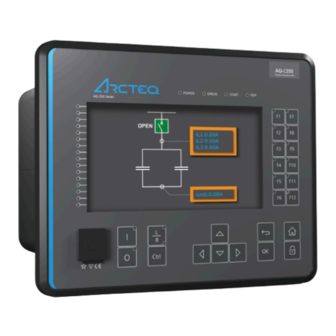
- Page 1 AQ-C255 Capacitor bank protection device Instruction manual...
-
Page 2: Table Of Contents
A A Q Q -C255 -C255 Instruction manual Version: 2.11 Table of contents 1 Document inf 1 Document informa ormation tion ..............................................6 6 1.1 Version 2 revision notes ......................6 1.2 Safety information ........................9 1.3 Abbreviations........................10 2 General 2 General............................ - Page 3 A A Q Q -C255 -C255 Instruction manual Version: 2.11 4.5.9 Programmable control switch .................. 282 4.5.10 User buttons......................283 4.5.11 Analog input scaling curves ................... 284 4.5.12 Logical outputs...................... 287 4.5.13 Logical inputs ......................288 4.6 Monitoring functions ......................290 4.6.1 Current transformer supervision ................
- Page 4 A A Q Q -C255 -C255 Instruction manual Version: 2.11 8.1.1 Measurements ......................399 8.1.1.1 Current measurement................. 399 8.1.1.2 Voltage measurement ................. 401 8.1.1.3 Voltage memory ..................401 8.1.1.4 Power and energy measurement..............402 8.1.1.5 Frequency measurement ................403 8.1.2 CPU & Power supply ....................403 8.1.2.1 Auxiliary voltage..................
- Page 5 A A Q Q -C255 -C255 Instruction manual Version: 2.11 8.2.3.5 Event logger ....................439 8.3 Tests and environmental ....................439 9 Or 9 Ordering inf dering informa ormation tion ..............................................442 10 Contact and r 10 Contact and re e f f er erence inf ence informa ormation tion..................
- Page 6 A A Q Q -C255 -C255 Instruction manual Version: 2.11 Disclaimer Please read these instructions carefully before using the equipment or taking any other actions with respect to the equipment. Only trained and qualified persons are allowed to perform installation, operation, service or maintenance of the equipment.
-
Page 7: Document Inf
A A Q Q -C255 -C255 1 Document information Instruction manual Version: 2.11 1 Document information 1.1 Version 2 revision notes Table. 1.1 - 1. Version 2 revision notes Revision 2.00 Date 6.6.2019 - New more consistent look. - Improved descriptions generally in many chapters. - Improved readability of a lot of drawings and images. - Page 8 A A Q Q -C255 -C255 1 Document information Instruction manual Version: 2.11 - Icol> function's Operating time settings updated. - Terminology consistency improved (e.g. binary inputs are now always called digital inputs). - Tech data modified to be more informative about what type of measurement inputs are used (phase currents/voltages, residual currents/voltages), what component of that measurement is available (RMS, TRMS, peak-to-peak) and possible calculated measurement values (powers, impedances, angles etc.).
- Page 9 A A Q Q -C255 -C255 1 Document information Instruction manual Version: 2.11 - Fixed phase current measurement continuous thermal withstand from 30A to 20A. - Fixed lots of timing errors written to registers table. "Prefault" is -200 ms from Start event, Changes "Pretrigger"...
-
Page 10: Safety Information
A A Q Q -C255 -C255 1 Document information Instruction manual Version: 2.11 - Updated the Arcteq logo on the cover page and refined the manual's visual look. - Added the "Safety information" chapter and changed the notes throughout the document accordingly. -
Page 11: Abbreviations
A A Q Q -C255 -C255 1 Document information Instruction manual Version: 2.11 Please note that although these warnings relate to direct damage to personnel and/or equipment, it should be understood that operating damaged equipment may also lead to further, indirect damage to personnel and/or equipment. - Page 12 A A Q Q -C255 -C255 1 Document information Instruction manual Version: 2.11 IDMT – Inverse definite minimum time IGBT – Insulated-gate bipolar transistor I/O – Input and output IRIG-B – Inter-range instruction group, timecode B LCD – Liquid-crystal display LED –...
-
Page 13: General
A A Q Q -C255 -C255 2 General Instruction manual Version: 2.11 2 General The AQ-C255 capacitor bank protection device is a member of the AQ 250 product line. The hardware and software are modular: the hardware modules are assembled and configured according to the application's I/O requirements, and the software determines the available functions. -
Page 14: Device User Int Vice User Interface Erface
A A Q Q -C255 -C255 3 Device user interface Instruction manual Version: 2.11 3 Device user interface 3.1 Panel structure The user interface section of an AQ 200 or AQ 250 series device is divided into two user interface sections: one for the hardware and the other for the software. -
Page 15: Configuring User Levels And Their Passwords
A A Q Q -C255 -C255 3 Device user interface Instruction manual Version: 2.11 When the unit is powered on, the green "Power" LED is lit. When the red "Error" LED is lit, the device has an internal (hardware or software) error that affects the operation of the unit. The activation of the yellow "Start"... - Page 16 A A Q Q -C255 -C255 3 Device user interface Instruction manual Version: 2.11 You can set a new password for a user level by selecting the key icon next to the user level's name. After this you can lock the user level by pressing the R R e e t t urn urn key while the lock is selected.
-
Page 17: Functions Unctions
A A Q Q -C255 -C255 4 Functions Instruction manual Version: 2.11 4 Functions 4.1 Functions included in AQ-C255 The AQ-C255 capacitor bank protection device includes the following functions as well as the number of stages for those functions. There are four function packages available: •... - Page 18 A A Q Q -C255 -C255 4 Functions Instruction manual Version: 2.11 Function package Name (number ANSI Description A B C D of stages) Harmonic overcurrent protection Ih> The detection and blocking or tripping Ih>> HOC (4) 50H/51H/68H based on a selectable harmonic. The Ih>>>...
- Page 19 A A Q Q -C255 -C255 4 Functions Instruction manual Version: 2.11 Function package Name (number ANSI Description A B C D of stages) ARC (1) Iarc>/I0arc> 50Arc/50NArc Arc fault protection (optional) Table. 4.1 - 3. Control functions of AQ-C255. Function package Name...
-
Page 20: Measurements
A A Q Q -C255 -C255 4 Functions Instruction manual Version: 2.11 4.2 Measurements 4.2.1 Current measurement and scaling The current measurement module (CT module, or CTM) is used for measuring the currents from current transformers. The current measurements are updated every 5 milliseconds. The measured values are processed into the measurement database and they are used by measurement and protection functions. - Page 21 A A Q Q -C255 -C255 4 Functions Instruction manual Version: 2.11 For the measurements to be correct the user needs to ensure that the measurement signals are connected to the correct inputs, that the current direction is connected to the correct polarity, and that the scaling is set according to the nominal values of the current transformer.
- Page 22 A A Q Q -C255 -C255 4 Functions Instruction manual Version: 2.11 Table. 4.2.1 - 5. Initial data. P P ha hase curr se current C ent CT T : : R R ing cor ing core C e CT in Input I02: T in Input I02: L L oad ( oad (nominal):...
- Page 23 A A Q Q -C255 -C255 4 Functions Instruction manual Version: 2.11 Figure. 4.2.1 - 5. Setting the phase current transformer scalings to the protected object's nominal current. Once the measurement scaling is tied to the protected object's nominal current, the user must set the appropriate input for the "Nominal current In"...
- Page 24 A A Q Q -C255 -C255 4 Functions Instruction manual Version: 2.11 Figure. 4.2.1 - 7. Residual I02 CT scaling (sensitive). Displaying the scaling Depending on whether the scaling was done based on the CT primary values or the protected object's nominal current, the measurements are displayed slightly differently.
- Page 25 A A Q Q -C255 -C255 4 Functions Instruction manual Version: 2.11 Example of zero sequence CT scaling Zero sequence CT scaling (ZCT scaling) is done when a zero sequence CT instead of a ring core CT is part of the measurement connection. In such a case the zero sequence CT should be connected to the I02 channel which has lower CT scaling ranges (see the image below).
- Page 26 A A Q Q -C255 -C255 4 Functions Instruction manual Version: 2.11 Problem Solution The phase currents are connected to the measurement module but the order or polarity of one or all phases is incorrect. In device settings, go to Measurement → Phasors and check the "Phase current vectors"...
- Page 27 A A Q Q -C255 -C255 4 Functions Instruction manual Version: 2.11 Figure. 4.2.1 - 11. Common phase polarity problems. The following image presents the most common problems with network rotation (mix phases). These problems can be difficult to find because the measurement result is always the same in the device. If two phases are mixed together, the network rotation always follows the pattern IL1-IL3-IL2 and the measured negative sequence current is therefore always 1.00 (in.
- Page 28 A A Q Q -C255 -C255 4 Functions Instruction manual Version: 2.11 Figure. 4.2.1 - 12. Common network rotation (mixed phases) problems. Settings Table. 4.2.1 - 6. Settings of the Phase CT scaling. Name Range Step Default Description Scale • CT nom p.u. •...
- Page 29 A A Q Q -C255 -C255 4 Functions Instruction manual Version: 2.11 Name Range Step Default Description A feedback value; the calculated scaling factor that is the ratio between the set primary current and the set CT scaling nominal current. This parameter is only visible if the factor NOM option "Object In p.u."...
- Page 30 A A Q Q -C255 -C255 4 Functions Instruction manual Version: 2.11 Table. 4.2.1 - 9. Per-unit phase current measurements. Name Unit Range Step Description Phase current 0.000…1 The current fundamental frequency component (in p.u.) × In 0.001 250.000 from each of the phase current channels. ("Pha.curr.ILx") Phase current ILx TRMS...
- Page 31 A A Q Q -C255 -C255 4 Functions Instruction manual Version: 2.11 Table. 4.2.1 - 13. Per-unit residual current measurements. Name Unit Range Step Description The current measurement fundamental frequency Residual current I0x 0.00…1 × In 0.01 component (in p.u.) from the residual current channel I01 ("Res.curr.I0x") 250.00 or I02.
- Page 32 A A Q Q -C255 -C255 4 Functions Instruction manual Version: 2.11 Table. 4.2.1 - 16. Residual phase angle measurements. Name Unit Range Step Description Residual current angle I0x The residual current angle measurement from the I01 or 0.00…360.00 0.01 ("Res.curr.angle I02 current input.
- Page 33 A A Q Q -C255 -C255 4 Functions Instruction manual Version: 2.11 Name Unit Range Step Description Secondary zero sequence current The secondary measurement from the calculated 0.00…300.00 0.01 ("Sec.Zero sequence zero sequence current. curr.") Table. 4.2.1 - 20. Sequence phase angle measurements. Name Unit Range...
-
Page 34: Voltage Measurement And Scaling
A A Q Q -C255 -C255 4 Functions Instruction manual Version: 2.11 4.2.2 Voltage measurement and scaling The voltage measurement module (VT module, or VTM) is used for measuring the voltages from voltage transformers. The voltage measurements are updated every 5 milliseconds. The measured values are processed into the measurement database and they are used by measurement and protection functions. - Page 35 A A Q Q -C255 -C255 4 Functions Instruction manual Version: 2.11 Figure. 4.2.2 - 14. Connections. The following table presents the initial data of the connection. Table. 4.2.2 - 22. Initial data. P P ha hase v se volta oltage V ge VT T Z Z er ero sequence v...
- Page 36 A A Q Q -C255 -C255 4 Functions Instruction manual Version: 2.11 Figure. 4.2.2 - 15. Example connections for voltage line-to-line measurement. If only two line-to-line voltages are measured, the third one (U ) is calculated based on the U vectors.
- Page 37 A A Q Q -C255 -C255 4 Functions Instruction manual Version: 2.11 The image collection below presents the device's behavior when nominal voltage is injected into the device via secondary test equipment. The measurement mode is 3LN+U4 which means that the device is measuring line-to-neutral voltages.
- Page 38 A A Q Q -C255 -C255 4 Functions Instruction manual Version: 2.11 Problem Check / Resolution The voltages are connected to the measurement module but the order or polarity of The measured one or all phases is incorrect. In device settings, go to Measurement → Phasors and voltage amplitudes are check the "System voltage vectors"...
- Page 39 A A Q Q -C255 -C255 4 Functions Instruction manual Version: 2.11 Name Range Step Default Description Defines how the secondary voltage is scaled to the primary. "Broken Delta" is the most common mode. Does not affect how protection operates, it only affects the displayed primary voltages.
- Page 40 A A Q Q -C255 -C255 4 Functions Instruction manual Version: 2.11 Name Range Step Default Description The selection of the fourth voltage measurement channel's (U4) polarity (direction). The default setting is for the U4 Polarity positive voltage to flow from connector 7 to connector 8, with the secondary voltage's starpoint pointing towards the line.
- Page 41 A A Q Q -C255 -C255 4 Functions Instruction manual Version: 2.11 Table. 4.2.2 - 26. Secondary voltage measurements. Name Range Step Description Secondary The secondary voltage measurement fundamental frequency voltage Ux 0.00…500.00V 0.01V component from each of the voltage channels. ("Ux Volt sec") Secondary voltage Ux...
- Page 42 A A Q Q -C255 -C255 4 Functions Instruction manual Version: 2.11 Table. 4.2.2 - 30. Secondary sequence voltage measurements. Name Range Step Description Secondary positive 0.00…4 The secondary measurement from the calculated positive sequence voltage 0.01V 800.00V sequence voltage. ("Pos.seq.Volt.sec") Secondary negative 0.00…4...
- Page 43 A A Q Q -C255 -C255 4 Functions Instruction manual Version: 2.11 Name Range Step Description System voltage magnitude 0.00…1 The primary line-to-neutral UL1 voltage fundamental frequency component 0.01V (measured or calculated). You can also select the row where the unit for this is ("System 000.00V volt UL1...
- Page 44 A A Q Q -C255 -C255 4 Functions Instruction manual Version: 2.11 Name Range Step Description System voltage angle UL23 0.00…360.00° 0.01° The primary line-to-line angle UL23 (measured or calculated). ("System volt UL23 ang") System voltage angle UL31 0.00…360.00° 0.01° The primary line-to-line angle UL23 (measured or calculated). ("System volt UL31 ang")
- Page 45 A A Q Q -C255 -C255 4 Functions Instruction manual Version: 2.11 Table. 4.2.2 - 34. Harmonic voltage measurements. Name Range Step Description Harmonics calculation values • Percent Defines whether the harmonics are calculated as percentages ("Harm Abs.or • Absolute or absolute values.
- Page 46 A A Q Q -C255 -C255 4 Functions Instruction manual Version: 2.11 Figure. 4.2.2 - 19. Distance protection characteristics and directional overcurrent. Voltage memory activates when the above-mentioned criteria are met. Voltage memory uses the "VMEM activation voltage" parameter as voltage amplitude even when the actual measured voltage has decreased below it or close to zero.
- Page 47 A A Q Q -C255 -C255 4 Functions Instruction manual Version: 2.11 VMEM activ VMEM activa a tion v tion volta oltage ge and Mea Measur sured curr ed current condition 3I> ent condition 3I> When the voltage memory function is enabled, it activates when all line voltages drop below the "VMEM activation voltage"...
-
Page 48: Power And Energy Calculation
A A Q Q -C255 -C255 4 Functions Instruction manual Version: 2.11 Event block name Event names M1VT1 Voltage memory blocked ON M1VT1 Voltage memory blocked OFF 4.2.3 Power and energy calculation Power is divided into three magnitudes: apparent power (S), active power (P) and reactive power (Q). Energy measurement calculates magnitudes for active and reactive energy. - Page 49 A A Q Q -C255 -C255 4 Functions Instruction manual Version: 2.11 Figure. 4.2.3 - 23. Three-phase reactive power (Q) calculation. Active power can be to the forward or the reverse direction. The direction of active power can be indicated with the power factor (Cos (φ), or Cosine phi), which is calculated according the following formula: The direction of reactive power is divided into four quadrants.
- Page 50 A A Q Q -C255 -C255 4 Functions Instruction manual Version: 2.11 If the line-to-line voltages are measured but the zero sequence voltage is not measured or is not otherwise known, the three-phase power calculation is based on Aron’s theorem: Both cos(φ) and tan(φ) are calculated in the same way as in the line-to-neutral mode.
- Page 51 A A Q Q -C255 -C255 4 Functions Instruction manual Version: 2.11 Name Range Step Default Description • Undefined • Q1 Fwd Cap AV Indicates what the power VA quadrant is at VA Quadrant • Q2 Rev Ind AV Undefined that moment.
- Page 52 A A Q Q -C255 -C255 4 Functions Instruction manual Version: 2.11 Name Range Step Default Description • 3PH.Fwd.Act.EP Selects whether the energy is active DC 1…4 • 3PH.Rev.Avt.EP or reactive, whether the direction of Input • 3PH.Fwd.React.EQ.CAP 3PH.Fwd.Act.EP the energy is forward of reverse, and signal •...
- Page 53 A A Q Q -C255 -C255 4 Functions Instruction manual Version: 2.11 Name Range Step Description 3PH Power factor 0.0001 The three-phase power factor -1x10 …1x10 Table. 4.2.3 - 40. Single-phase power calculations (L1...L3). Name Unit Range Step Description Lx Apparent power (S) kVA 0.01 The apparent power of Phase Lx in kilo-volt-amperes -1x10...
- Page 54 A A Q Q -C255 -C255 4 Functions Instruction manual Version: 2.11 Name Range Step Description Apparent Energy (S) while Export The total amount of exported apparent energy 0.01 -1x10 …1x10 (P) (kVAh or MVAh) while active energy is exported. Apparent Energy (S) while Import The total amount of exported apparent energy 0.01...
- Page 55 A A Q Q -C255 -C255 4 Functions Instruction manual Version: 2.11 Name Value Name Value Name Value Name Value L1 (S) L1 (S) 4.08 MVA L2 (S) L2 (S) 6.15 MVA L3 (S) L3 (S) 9.77 MVA 3PH (S) H (S) 20.00 MVA L1 (P)
-
Page 56: Frequency Tracking And Scaling
A A Q Q -C255 -C255 4 Functions Instruction manual Version: 2.11 Name Values 3PH (S) 20.00 MVA 3PH (P) 17.32 MW 3PH (Q) 0.00 Mvar 3PH Tan 0.00 3PH Cos 0.87 4.2.4 Frequency tracking and scaling Measurement sampling can be set to the frequency tracking mode or to the fixed user- defined frequency sampling mode. - Page 57 A A Q Q -C255 -C255 4 Functions Instruction manual Version: 2.11 The measurement error with a fixed 50 Hz sampling The measurement error with frequency tracking frequency when the frequency changes. The constant when the frequency changes. The constant current current is 5 A, the frequency sweep is from 6 Hz to 75 is 5 A, the frequency sweep is from 6 Hz to 75 Hz.
- Page 58 A A Q Q -C255 -C255 4 Functions Instruction manual Version: 2.11 Name Range Step Default Description Sampling Displays the tracking frequency that is in use at frequency in 0.000…75.000Hz 0.001Hz - that moment. • None • CT1IL1 Frequency • CT2IL1 CT1IL1 The first reference source for frequency tracking.
-
Page 59: General Menu
A A Q Q -C255 -C255 4 Functions Instruction manual Version: 2.11 Name Range Step Default Description Tracked f Displays the rough value of the tracked frequency 0.000…75.000Hz 0.001Hz - channel A in Channel A. Tracked f Displays the rough value of the tracked frequency 0.000…75.000Hz 0.001Hz - channel B in Channel B. - Page 60 A A Q Q -C255 -C255 4 Functions Instruction manual Version: 2.11 Table. 4.3 - 45. The General menu read-only parameters Name Description Serial number The unique serial number identification of the unit. Firmware version The firmware software version of the unit. Hardware configuration The order code identification of the unit.
- Page 61 A A Q Q -C255 -C255 4 Functions Instruction manual Version: 2.11 Name Range Default Description • All • COM A If the device has a double Ethernet option card it is possible to AQtivate • Double choose which ports are available for connecting with AQtivate ethernet port Ethernet software.
-
Page 62: Protection Functions
A A Q Q -C255 -C255 4 Functions Instruction manual Version: 2.11 Name Range Default Description Reconfigure • - Reloads the mimic to the unit. mimic • Reconfigure Table. 4.3 - 47. General menu logical inputs. Name Description Reset last fault registers Signal set to this point can be used for resetting latest recorded fault register. - Page 63 A A Q Q -C255 -C255 4 Functions Instruction manual Version: 2.11 Capacitor units should be suitable for continuous operation at up to 135 % of the rated reactive power caused by the combined effects of: • Voltage that is higher than the name plate rating at the fundamental frequency, but not over 110 % of the rated RMS voltage.
- Page 64 A A Q Q -C255 -C255 4 Functions Instruction manual Version: 2.11 Delta-connected banks are generally used only at distribution voltages and are configured with a single series group of capacitors rated at line-to-line voltage. With only one series group of units unbalance detection is not required for protection.
-
Page 65: Capacitor Bank Overload Protection (Icol>; 49Ol)
A A Q Q -C255 -C255 4 Functions Instruction manual Version: 2.11 Please note that harmonic voltages and currents can influence the operation of the unbalance protection function unless a power frequency band-pass or other appropriate filtering is provided. A A bout the bout the opera operating time ting time... - Page 66 A A Q Q -C255 -C255 4 Functions Instruction manual Version: 2.11 Signal Description Time base Fundamental frequency component of phase L2 (B) current Fundamental frequency component of phase L3 (C) current TRMS TRMS measurement of phase L1 (A) current TRMS TRMS measurement of phase L2 (B) current TRMS...
- Page 67 A A Q Q -C255 -C255 4 Functions Instruction manual Version: 2.11 Table. 4.4.2 - 50. Pick-up settings. Name Description Range Step Default Pick-up setting 0.10…50.00×I 0.01×I 1.20×I Read-only parameters The function's Info page displays useful, real-time information on the state of the protection function. It is accessed either through the device's HMI display, or through the setting tool software when it is connected to the device and its Live Edit mode is active.
- Page 68 A A Q Q -C255 -C255 4 Functions Instruction manual Version: 2.11 Name Range Step Default Description harmonic blocking limit Defines the limit of the 2 0.10…50.00%I 0.01%I 0.01%I fund fund fund (Iharm/Ifund) harmonic blocking. If the blocking signal is active when the pick-up element activates, a BLOCKED signal is generated and the function does not process the situation further.
- Page 69 A A Q Q -C255 -C255 4 Functions Instruction manual Version: 2.11 Name Range Step Default Description Operating Allows the testing of the expected operating time with curve test 1.00...40.00 0.01 1.00 the given I value with an online relay. meas (online) The IDMT curve formula used to calculate the segment timing behaviour is shown below:...
-
Page 70: Capacitor Bank Neutral Unbalance Protection (Cnu>; 50Ub)
A A Q Q -C255 -C255 4 Functions Instruction manual Version: 2.11 Events and registers The capacitor bank overload function (abbreviated "COL" in event block names) generates events and registers from the status changes in the events listed below. The user can select which event messages are stored in the main event buffer: ON, OFF, or both. - Page 71 A A Q Q -C255 -C255 4 Functions Instruction manual Version: 2.11 Figure. 4.4.3 - 28. Simplified function block diagram of the Cnu> function. Measured input The function block uses current measurement values from the residual current inputs I and I well as the three phase current measurement inputs.
- Page 72 A A Q Q -C255 -C255 4 Functions Instruction manual Version: 2.11 Name Range Default Description • Normal • Alarm Start CNU> (50UB) • Alarm On Force the status of the function. Visible only when Enable stage force status Normal •...
- Page 73 A A Q Q -C255 -C255 4 Functions Instruction manual Version: 2.11 Name Range Step Default Description Defines the pick-up threshold per side for counted fuse Pick-up operations. setting for fuse 1…50 fuses 1 fuse 3 fuses Please note that this setting requires that the "Count fuse operations operations per side for action"...
- Page 74 A A Q Q -C255 -C255 4 Functions Instruction manual Version: 2.11 Table. 4.4.3 - 58. Information displayed by the function. Name Range Step Description • On Displays the mode of CNU block. • Blocked CNU> (50UB) • Test This parameter is visible only when Allow setting of LN behaviour •...
- Page 75 A A Q Q -C255 -C255 4 Functions Instruction manual Version: 2.11 Table. 4.4.3 - 59. Internal inrush harmonic blocking settings. Name Range Step Default Description Inrush harmonic blocking • No Enables and disables the 2 (internal-only trip) • Yes harmonic blocking.
-
Page 76: Capacitor Bank Current Unbalance Protection (Iuc>; 46C)
A A Q Q -C255 -C255 4 Functions Instruction manual Version: 2.11 Event block name Event names CNU1 Unbalance detected Bank A OFF CNU1 Unbalance detected Bank B ON CNU1 Unbalance detected Bank B OFF CNU1 Compensating natural unbalance ON CNU1 Compensating natural unbalance OFF The function registers its operation into the last twelve (12) time-stamped registers;... - Page 77 A A Q Q -C255 -C255 4 Functions Instruction manual Version: 2.11 General settings The following general settings define the general behavior of the function. These settings are static i.e. it is not possible to change them by editing the setting group. Table.
- Page 78 A A Q Q -C255 -C255 4 Functions Instruction manual Version: 2.11 Setting group selection controls the operating characteristics of the function, i.e. the user or user- defined logic can change function parameters while the function is running. Table. 4.4.4 - 64. Pick-up settings. Name Range Step...
- Page 79 A A Q Q -C255 -C255 4 Functions Instruction manual Version: 2.11 Name Range Step Description Displays the expected operating time when a fault occurs. When IDMT mode is used, the expected operating time Expected time -1800.000...1800.000s 0.005s depends on the measured highest phase current value. If to Trip the measured current changes during a fault, the expected operating time changes accordingly.
-
Page 80: Non-Directional Overcurrent Protection (I>; 50/51)
A A Q Q -C255 -C255 4 Functions Instruction manual Version: 2.11 Table. 4.4.4 - 67. Event messages. Event block name Event names UCP1 Alarm Start ON UCP1 Alarm Start OFF UCP1 Alarm ON UCP1 Alarm OFF UCP1 Start ON UCP1 Start OFF UCP1... - Page 81 A A Q Q -C255 -C255 4 Functions Instruction manual Version: 2.11 Figure. 4.4.5 - 30. Simplified function block diagram of the I> function. Measured input The function block uses phase current measurement values. The user can select the monitored magnitude to be equal either to RMS values (fundamental frequency component), to TRMS values from the whole harmonic specter of 32 components, or to peak-to-peak values.
- Page 82 A A Q Q -C255 -C255 4 Functions Instruction manual Version: 2.11 Name Range Default Description • On • Blocked Set mode of NOC block. • Test I> LN mode • On This parameter is visible only when Allow setting of individual •...
- Page 83 A A Q Q -C255 -C255 4 Functions Instruction manual Version: 2.11 Table. 4.4.5 - 72. Information displayed by the function. Name Range Step Description • On Displays the mode of NOC block. • Blocked I> LN • Test This parameter is visible only when Allow setting of individual LN behaviour •...
- Page 84 A A Q Q -C255 -C255 4 Functions Instruction manual Version: 2.11 Name Range Step Default Description harmonic blocking limit Defines the limit of the 2 0.10…50.00%I 0.01%I 0.01%I fund fund fund (Iharm/Ifund) harmonic blocking. If the blocking signal is active when the pick-up element activates, a BLOCKED signal is generated and the function does not process the situation further.
- Page 85 A A Q Q -C255 -C255 4 Functions Instruction manual Version: 2.11 Table. 4.4.5 - 74. Event messages. Event block name Event names NOC1...NOC4 Start ON NOC1...NOC4 Start OFF NOC1...NOC4 Trip ON NOC1...NOC4 Trip OFF NOC1...NOC4 Block ON NOC1...NOC4 Block OFF NOC1...NOC4 Phase A Start ON NOC1...NOC4...
-
Page 86: Non-Directional Earth Fault Protection (I0>; 50N/51N)
A A Q Q -C255 -C255 4 Functions Instruction manual Version: 2.11 Name Description Trip time remaining 0 ms...1800s Setting group in use Setting group 1...8 active. 4.4.6 Non-directional earth fault protection (I0>; 50N/51N) The non-directional earth fault function is used for instant and time-delayed earth fault protection. The number of stages in the function depend on the device model. - Page 87 A A Q Q -C255 -C255 4 Functions Instruction manual Version: 2.11 Time Signal Description base Fundamental frequency component of the calculated zero sequence current calculated 5 ms 0Calc from the three phase currents General settings The following general settings define the general behavior of the function. These settings are static i.e. it is not possible to change them by editing the setting group.
- Page 88 A A Q Q -C255 -C255 4 Functions Instruction manual Version: 2.11 Table. 4.4.6 - 78. Pick-up settings. Name Description Range Step Default Pick-up setting 0.0001…40.00 × I 0.0001 × I 1.20 × I Read-only parameters The function's Info page displays useful, real-time information on the state of the protection function. It is accessed either through the device's HMI display, or through the setting tool software when it is connected to the device and its Live Edit mode is active.
- Page 89 A A Q Q -C255 -C255 4 Functions Instruction manual Version: 2.11 Function blocking The block signal is checked in the beginning of each program cycle. The blocking signal is received from the blocking matrix in the function's dedicated input. Additionally, the function includes an internal inrush harmonic blocking option which is applied according to the parameters set by the user.
-
Page 90: Directional Overcurrent Protection (Idir>; 67)
A A Q Q -C255 -C255 4 Functions Instruction manual Version: 2.11 Event block name Event names NEF1...NEF4 Block ON NEF1...NEF4 Block OFF The function registers its operation into the last twelve (12) time-stamped registers. The register of the function records the ON event process data for START, TRIP or BLOCKED. The table below presents the structure of the function's register content. - Page 91 A A Q Q -C255 -C255 4 Functions Instruction manual Version: 2.11 Measured input The function block uses phase current and voltage measurement values. The user can select the monitored current magnitude to be equal either to RMS values (fundamental frequency component), to TRMS values from the whole harmonic specter of 32 components, or to peak-to-peak values.
- Page 92 A A Q Q -C255 -C255 4 Functions Instruction manual Version: 2.11 Name Range Default Description • Normal Force the status of the function. Visible only when Enable stage Idir> force • Start Normal status to • Trip forcing parameter is enabled in General menu. •...
- Page 93 A A Q Q -C255 -C255 4 Functions Instruction manual Version: 2.11 Figure. 4.4.7 - 34. Angle tracking of the Idir> function (3LN/3LL + U mode). Please note in the picture above that the tripping area is linked to the angle of the positive sequence voltage U .
- Page 94 A A Q Q -C255 -C255 4 Functions Instruction manual Version: 2.11 Figure. 4.4.7 - 36. When Idir> function has been set to "Non-directional" the function works basically just like a traditional non-directional overcurrent protection function. Read-only parameters The function's Info page displays useful, real-time information on the state of the protection function. It is accessed either through the device's HMI display, or through the setting tool software when it is connected to the device and its Live Edit mode is active.
- Page 95 A A Q Q -C255 -C255 4 Functions Instruction manual Version: 2.11 Name Range Step Description meas The ratio between the highest measured phase current and the 0.00...1250.00I 0.01I at the pick-up value. moment Function blocking The block signal is checked in the beginning of each program cycle. The blocking signal is received from the blocking matrix in the function's dedicated input.
-
Page 96: Directional Earth Fault Protection (I0Dir>; 67N/32N)
A A Q Q -C255 -C255 4 Functions Instruction manual Version: 2.11 Event block name Event names DOC1...DOC4 Start OFF DOC1...DOC4 Trip ON DOC1...DOC4 Trip OFF DOC1...DOC4 Block ON DOC1...DOC4 Block OFF DOC1...DOC4 No voltage, Blocking ON DOC1...DOC4 Voltage measurable, Blocking OFF DOC1...DOC4 Measuring live angle ON DOC1...DOC4... - Page 97 A A Q Q -C255 -C255 4 Functions Instruction manual Version: 2.11 Figure. 4.4.8 - 37. Simplified function block diagram of the I0dir> function. Measured input The function block uses residual current measurement values and neutral voltage measurement values. The available residual current measurement channels are I and I (residual current measurement) and I0Calc (residual current calculated from phase current).The user can select the...
- Page 98 A A Q Q -C255 -C255 4 Functions Instruction manual Version: 2.11 General settings The following general settings define the general behavior of the function. These settings are static i.e. it is not possible to change them by editing the setting group. Table.
- Page 99 A A Q Q -C255 -C255 4 Functions Instruction manual Version: 2.11 Table. 4.4.8 - 92. Pick-up settings. Name Range Step Default Description 0.005…40.00×I 0.001×I 1.20×I Current pick-up setting 1…75%U 0.01%U 20%U Voltage pick-up setting • Unearthed [32N Var] • Petersen coil GND [32N Watt] Grounding...
- Page 100 A A Q Q -C255 -C255 4 Functions Instruction manual Version: 2.11 Unearthed network Figure. 4.4.8 - 38. Angle tracking of I0dir> function (unearthed network model) (32N) When the unearthed (capacitive) network mode is chosen, the function expects the fault current to be lagging zero sequence voltage by 90 degrees.
- Page 101 A A Q Q -C255 -C255 4 Functions Instruction manual Version: 2.11 The resistance of the fault affects the size of the voltage drop during a fault. In direct earth fault the zero sequence voltage amplitude is equal to the system's line-to-earth voltage. In direct earth fault the voltage of a faulty phase drops close to zero and healthy phase voltages increase to the amplitude of line-to-line voltages.
- Page 102 A A Q Q -C255 -C255 4 Functions Instruction manual Version: 2.11 When the Petersen coil earthed (compensated) network mode is chosen, the function expects the fault current to be in the opposite direction to the zero sequence voltage. Healthy phases of both healthy and faulty feeders produce a capacitive current similar to the unearthed network.
- Page 103 A A Q Q -C255 -C255 4 Functions Instruction manual Version: 2.11 Directly earthed or small impedance network (67N) Figure. 4.4.8 - 40. Angle tracking of I0dir> function (directly earthed or small impedance network). In a directly earthed network the amplitude of a single-phase fault current is similar to the amplitude of a short-circuit current.
- Page 104 A A Q Q -C255 -C255 4 Functions Instruction manual Version: 2.11 Broad range mode with multi-criteria detection for unearthed and compensated networks When detecting earth faults in compensated long-distance cables and overhead lines, it is in some cases difficult to distinguish between a healthy and a faulty feeder. Merely measuring the angle and the magnitude of residual voltage and currents is not always enough, as changes in symmetrical components of phase currents and voltages are also needed.
- Page 105 A A Q Q -C255 -C255 4 Functions Instruction manual Version: 2.11 The new broad range mode is capable of detecting an earth fault directionally in both unearthed and compensated networks not only by combining the two stages together but by using a new multi-criteria detection.
- Page 106 A A Q Q -C255 -C255 4 Functions Instruction manual Version: 2.11 Name Range Step Description • Normal I0dir> • Start Displays the status of the protection function. condition • Trip • Blocked Displays which voltage channel is used by the function. If no voltage channel has been selected the function •...
- Page 107 A A Q Q -C255 -C255 4 Functions Instruction manual Version: 2.11 Table. 4.4.8 - 94. Internal inrush harmonic blocking settings. Name Range Step Default Description Inrush harmonic blocking • No Enables and disables the 2 (internal-only trip) • Yes harmonic blocking.
-
Page 108: Intermittent Earth Fault Protection (I0Int>; 67Nt)
A A Q Q -C255 -C255 4 Functions Instruction manual Version: 2.11 Event block name Event name DEF1...DEF4 I0Sinfi Start OFF DEF1...DEF4 I0Cosfi Trip ON DEF1...DEF4 I0Cosfi Trip OFF DEF1...DEF4 I0Sinfi Trip ON DEF1...DEF4 I0Sinfi Trip OFF The function registers its operation into the last twelve (12) time-stamped registers; this information is available for all provided instances separately. - Page 109 A A Q Q -C255 -C255 4 Functions Instruction manual Version: 2.11 This phenomenon is becoming more frequent as more utilities networks are replacing overhead lines with cables dug into the ground. This development in distribution networks is very understandable as overhead lines are more vulnerable to possible seasonal storm damages.
- Page 110 A A Q Q -C255 -C255 4 Functions Instruction manual Version: 2.11 Figure. 4.4.9 - 43. An intermittent earth fault in a medium size network tuned close to resonance, as seen by a protection relay of a faulty feeder. © Arcteq Relays Ltd IM00035...
- Page 111 A A Q Q -C255 -C255 4 Functions Instruction manual Version: 2.11 Figure. 4.4.9 - 44. An intermittent earth fault in a network tuned close to resonance, as seen by a protection relay of a healthy feeder. © Arcteq Relays Ltd IM00035...
- Page 112 A A Q Q -C255 -C255 4 Functions Instruction manual Version: 2.11 Figure. 4.4.9 - 45. An intermittent earth fault in an undercompensated medium size network, as seen by protection relay of a faulty feeder. © Arcteq Relays Ltd IM00035...
- Page 113 A A Q Q -C255 -C255 4 Functions Instruction manual Version: 2.11 Figure. 4.4.9 - 46. Undercompensated medium size network intermittent earth fault seen by a protection relay of a healthy feeder. As can be seen from the figures above, the residual voltage is high both in the network tuned close to resonance and in the undercompensated network.
- Page 114 A A Q Q -C255 -C255 4 Functions Instruction manual Version: 2.11 More detailed information of the patent can be found on the European Patent Office webpages. The patent's data code is EP3213381 (A1). A link to the patent: https://worldwide.espacenet.com/publicationDetails/ biblio?II=2&ND=3&adjacent=true&locale=en_EP&FT=D&date=20170906&CC=EP&NR=3213381A1&KC=A1.
- Page 115 A A Q Q -C255 -C255 4 Functions Instruction manual Version: 2.11 Setting parameter Value Definite operating time delay 0.500 s Spikes to trip > The best verification for the settings is a field test with a test system capable of intermittent earth faults. One network characteristic may vary significantly from another.
- Page 116 A A Q Q -C255 -C255 4 Functions Instruction manual Version: 2.11 Pick-up settings The setting parameters U0 Detect spike> and I0 Detect spike > control the pick-up of the I0int> function. They define the maximum allowed measured residual current and voltage before action from the function.
- Page 117 A A Q Q -C255 -C255 4 Functions Instruction manual Version: 2.11 Function blocking The block signal is checked in the beginning of each program cycle. The blocking signal is received from the blocking matrix in the function's dedicated input. If the blocking signal is not activated when the pick-up element activates, a START signal is generated and the function proceeds to the time characteristics calculation.
- Page 118 A A Q Q -C255 -C255 4 Functions Instruction manual Version: 2.11 The function's outputs can be used for direct I/O controlling and user logic programming. The function also provides a cumulative counter for the START, TRIP and BLOCKED events. Table.
-
Page 119: Negative Sequence Overcurrent/ Phase Current Reversal/ Current Unbalance Protection (I2>; 46/46R/46L)
A A Q Q -C255 -C255 4 Functions Instruction manual Version: 2.11 4.4.10 Negative sequence overcurrent/ phase current reversal/ current unbalance protection (I2>; 46/46R/46L) The current unbalance function is used for instant and time-delayed unbalanced network protection and for detecting broken conductors. The number of stages in the function depends on the device model. - Page 120 A A Q Q -C255 -C255 4 Functions Instruction manual Version: 2.11 Signal Description Time base Fundamental frequency component of phase L1 (A) current measurement 5 ms Fundamental frequency component of phase L2 (B) current measurement 5 ms Fundamental frequency component of phase L3 (C) current measurement 5 ms General settings The following general settings define the general behavior of the function.
- Page 121 A A Q Q -C255 -C255 4 Functions Instruction manual Version: 2.11 Read-only parameters The function's Info page displays useful, real-time information on the state of the protection function. It is accessed either through the device's HMI display, or through the setting tool software when it is connected to the device and its Live Edit mode is active.
- Page 122 A A Q Q -C255 -C255 4 Functions Instruction manual Version: 2.11 • t = Operating time • I = Calculated negative sequence 2meas • k = Constant k value (user settable delay multiplier) • I = Pick-up setting of the function Figure.
-
Page 123: Harmonic Overcurrent Protection (Ih>; 50H/51H/68H)
A A Q Q -C255 -C255 4 Functions Instruction manual Version: 2.11 Table. 4.4.10 - 108. Event messages. Event block name Event names CUB1...CUB4 Start ON CUB1...CUB4 Start OFF CUB1...CUB4 Trip ON CUB1...CUB4 Trip OFF CUB1...CUB4 Block ON CUB1...CUB4 Block OFF The function registers its operation into the last twelve (12) time-stamped registers. - Page 124 A A Q Q -C255 -C255 4 Functions Instruction manual Version: 2.11 Figure. 4.4.11 - 49. Simplified function block diagram of the Ih> function. Measured input The function block uses analog current measurement values from phase or residual currents. Each measurement input of the function block uses RMS (fundamental frequency component) values and harmonic components of the selected current input.
- Page 125 A A Q Q -C255 -C255 4 Functions Instruction manual Version: 2.11 Signal Description Time base The magnitudes (RMS) of phase L2 (B) current components: - Fundamental harmonic harmonic harmonic harmonic harmonic 5 ms harmonic harmonic - 11 harmonic - 13 harmonic - 15 harmonic...
- Page 126 A A Q Q -C255 -C255 4 Functions Instruction manual Version: 2.11 Signal Description Time base The magnitudes (RMS) of residual I0 current components: - Fundamental harmonic harmonic harmonic harmonic harmonic 5 ms harmonic harmonic - 11 harmonic - 13 harmonic - 15 harmonic...
- Page 127 A A Q Q -C255 -C255 4 Functions Instruction manual Version: 2.11 Name Range Default Description • 2 harmonic • 3 harmonic • 4 harmonic • 5 harmonic • 6 harmonic • 7 Harmonic harmonic Selection of the monitored harmonic component. selection harmonic •...
- Page 128 A A Q Q -C255 -C255 4 Functions Instruction manual Version: 2.11 Name Range Step Default Description Pick-up setting Ih/IL 5.00…200.00% 0.01% 20.00% (percentage monitoring) Read-only parameters The function's Info page displays useful, real-time information on the state of the protection function. It is accessed either through the device's HMI display, or through the setting tool software when it is connected to the device and its Live Edit mode is active.
- Page 129 A A Q Q -C255 -C255 4 Functions Instruction manual Version: 2.11 Operating time characteristics for trip and reset This function supports definite time delay (DT) and inverse definite minimum time delay (IDMT). For detailed information on these delay types please refer to the chapter "General properties of a protection function"...
-
Page 130: Circuit Breaker Failure Protection (Cbfp; 50Bf/52Bf)
A A Q Q -C255 -C255 4 Functions Instruction manual Version: 2.11 4.4.12 Circuit breaker failure protection (CBFP; 50BF/52BF) The circuit breaker failure protection function is used for monitoring the circuit breaker operation after it has received a TRIP signal. The function can also be used to retrip a failing breaker; if the retrip fails, an incoming feeder circuit breaker can be tripped by using the function's CBFP output. - Page 131 A A Q Q -C255 -C255 4 Functions Instruction manual Version: 2.11 Signal Description Time base Fundamental frequency component of residual input I measurement Calculated residual current from the phase current inputs 0Calc General settings The following general settings define the general behavior of the function. These settings are static i.e. it is not possible to change them by editing the setting group.
- Page 132 A A Q Q -C255 -C255 4 Functions Instruction manual Version: 2.11 Table. 4.4.12 - 119. Operating mode and input signals selection. Name Range Step Default Description • Not in Selects the residual current monitoring source, which can be Not in I0Input •...
- Page 133 A A Q Q -C255 -C255 4 Functions Instruction manual Version: 2.11 Table. 4.4.12 - 121. Information displayed by the function. Name Range Description • On • Blocked Displays the mode of CBF block. CBFP LN • Test This parameter is visible only when Allow setting of individual LN mode is behaviour •...
- Page 134 A A Q Q -C255 -C255 4 Functions Instruction manual Version: 2.11 The following figures present some typical cases of the CBFP function. Trip, Retrip and CBFP in the device configuration Figure. 4.4.12 - 51. Wiring diagram when Trip, Retrip and CBFP are configured to the device. The retrip functionality can be used in applications whose circuit breaker has a retrip or a redundant trip coil available.
- Page 135 A A Q Q -C255 -C255 4 Functions Instruction manual Version: 2.11 Figure. 4.4.12 - 52. Retrip and CBFP when "Current" is the selected criterion. When the current threshold setting of I and/or I0 is exceeded, the current-based protection is activated and the counters for RETRIP and CBFP start calculating the set operating time.
- Page 136 A A Q Q -C255 -C255 4 Functions Instruction manual Version: 2.11 Figure. 4.4.12 - 53. Retrip and CBFP when "Current and DO" is the selected criterion. When the current threshold setting of I and/or I0 is exceeded, the current-based protection is activated.
- Page 137 A A Q Q -C255 -C255 4 Functions Instruction manual Version: 2.11 Figure. 4.4.12 - 54. Retrip and CBFP when "Current or DO" is the selected criterion. When the current threshold setting of I and/or I0 is exceeded, or the TRIP signal reaches the primary protection stage, the function starts counting down towards the RETRIP and CBFP signals.
- Page 138 A A Q Q -C255 -C255 4 Functions Instruction manual Version: 2.11 Trip and CBFP in the device configuration Figure. 4.4.12 - 55. Wiring diagram when Trip and CBFP are configured to the device. Probably the most common application is when the device's trip output controls the circuit breaker trip coil, while one dedicated CBFP contact controls the CBFP function.
- Page 139 A A Q Q -C255 -C255 4 Functions Instruction manual Version: 2.11 Figure. 4.4.12 - 56. CBFP when "Current" is the selected criterion. When the current threshold setting of I and/or I0 is exceeded, the current-based protection is activated and the counter for CBFP starts calculating the set operating time. The tripping of the primary protection stage is not monitored in this configuration.
- Page 140 A A Q Q -C255 -C255 4 Functions Instruction manual Version: 2.11 Figure. 4.4.12 - 57. CBFP when "Current and DO" is the selected criterion. When the current threshold setting of I and/or I0 is exceeded, the current-based protection is activated.
- Page 141 A A Q Q -C255 -C255 4 Functions Instruction manual Version: 2.11 Figure. 4.4.12 - 58. CBFP when "Current or DO" is the selected criterion. When the current threshold setting of I and/or I0 is exceeded, or the TRIP signal reaches the primary protection stage, the function starts counting down towards the CBFP signal.
- Page 142 A A Q Q -C255 -C255 4 Functions Instruction manual Version: 2.11 Device configuration as a dedicated CBFP unit Figure. 4.4.12 - 59. Wiring diagram when the device is configured as a dedicated CBFP unit. © Arcteq Relays Ltd IM00035...
- Page 143 A A Q Q -C255 -C255 4 Functions Instruction manual Version: 2.11 Some applications require a dedicated circuit breaker protection unit. When the CBFP function is configured to operate with a digital input signal, it can be used in these applications. When a device is used for this purpose, the tripping signal is wired to the device's digital input and the device's own TRIP signal is used only for the CBFP purpose.
- Page 144 A A Q Q -C255 -C255 4 Functions Instruction manual Version: 2.11 Event block name Event names CBF1 Retrip ON CBF1 Retrip OFF CBF1 CBFP ON CBF1 CBFP OFF CBF1 Block ON CBF1 Block OFF CBF1 DO monitor ON CBF1 DO monitor OFF CBF1 Signal ON...
-
Page 145: Low-Impedance Or High-Impedance Restricted Earth Fault/ Cable End Differential Protection (I0D>; 87N)
A A Q Q -C255 -C255 4 Functions Instruction manual Version: 2.11 4.4.13 Low-impedance or high-impedance restricted earth fault/ cable end differential protection (I0d>; 87N) The low-impedance or high-impedance restricted earth fault function is used for residual differential current measurement for transformers. This function can also be used as the cable end differential function. - Page 146 A A Q Q -C255 -C255 4 Functions Instruction manual Version: 2.11 Signal Description Time base Angle of phase L2 (B) current Angle of phase L3 (C) current Angle of residual input I01 Angle of residual input I02 General settings The following general settings define the general behavior of the function.
- Page 147 A A Q Q -C255 -C255 4 Functions Instruction manual Version: 2.11 Name Range Step Default Description Differential current calculation mode. This matches the directions of the calculated and measured residual currents to the application. The default setting (Add) means that •...
- Page 148 A A Q Q -C255 -C255 4 Functions Instruction manual Version: 2.11 Figure. 4.4.13 - 63. "I0 direction" parameter must be set to "Add" when current transformers are facing each other or away from each other. The following figure presents the differential characteristics with default settings. Figure.
- Page 149 A A Q Q -C255 -C255 4 Functions Instruction manual Version: 2.11 Figure. 4.4.13 - 66. Bias current (the calculation is based on the user-selected mode). Figure. 4.4.13 - 67. Characteristics settings. Read-only parameters The function's Info page displays useful, real-time information on the state of the protection function. It is accessed either through the device's HMI display, or through the setting tool software when it is connected to the device and its Live Edit mode is active.
- Page 150 A A Q Q -C255 -C255 4 Functions Instruction manual Version: 2.11 {{Default-Series}}. 4.4.13 - 1. The following figures present some typical applications for this function. Figure. 4.4.13 - 68. Cable end differential with natural unbalance in the phase current measurement. When calculating residual current from the phase currents, the natural unbalance can be around 10 % while the used CTs are still within the promised 5P class (which is probably the most common CT accuracy class).
- Page 151 A A Q Q -C255 -C255 4 Functions Instruction manual Version: 2.11 Figure. 4.4.13 - 69. Cable end differential when a fault occurs. If a starting fault occurs in the cable end, the CED mode catches the difference between the ingoing and the outgoing residual currents.
- Page 152 A A Q Q -C255 -C255 4 Functions Instruction manual Version: 2.11 Figure. 4.4.13 - 70. Restricted earth fault outside a Y winding transformer. If the fault is located inside of the transformer and thus inside of the protection area, the function catches the fault with high sensitivity.
- Page 153 A A Q Q -C255 -C255 4 Functions Instruction manual Version: 2.11 Figure. 4.4.13 - 71. Restricted earth fault inside a Y winding transformer. Events and registers The restricted earth fault function (abbreviated "REF" in event block names) generates events and registers from the status changes in the events listed below.
-
Page 154: Overvoltage Protection (U>; 59)
A A Q Q -C255 -C255 4 Functions Instruction manual Version: 2.11 Table. 4.4.13 - 129. Event messages. Event block name Event names REF1 I0d> (87N) Trip ON REF1 I0d> (87N) Trip OFF REF1 I0d> (87N) Block ON REF1 I0d> (87N) Block OFF The function registers its operation into the last twelve (12) time-stamped registers. - Page 155 A A Q Q -C255 -C255 4 Functions Instruction manual Version: 2.11 Figure. 4.4.14 - 72. Simplified function block diagram of the U> function. Measured input The function block uses fundamental frequency component of line-to-line or line-to-neutral (as the user selects).
- Page 156 A A Q Q -C255 -C255 4 Functions Instruction manual Version: 2.11 Figure. 4.4.14 - 73. Selectable measurement magnitudes with 3LN+U4 VT connection. Figure. 4.4.14 - 74. Selectable measurement magnitudes with 3LL+U4 VT connection (P-E voltages not available without residual voltage). ©...
- Page 157 A A Q Q -C255 -C255 4 Functions Instruction manual Version: 2.11 Figure. 4.4.14 - 75. Selectable measurement magnitudes with 2LL+U3+U4 VT connection (P-E voltages not available without residual voltage). P-P Voltages and P-E Voltages selections follow phase-to-neutral or phase-to-phase voltages in the first three voltage channels (or two first voltage channels in the 2LL+U3+U4 mode).
- Page 158 A A Q Q -C255 -C255 4 Functions Instruction manual Version: 2.11 Table. 4.4.14 - 134. Pick-up settings. Name Range Step Default Description • 1 voltage Operation mode • 2 voltages 1 voltage Pick-up criteria selection • 3 voltages 50.00…150.00%U 0.01%U 105%U Pick-up setting...
- Page 159 A A Q Q -C255 -C255 4 Functions Instruction manual Version: 2.11 Function blocking The block signal is checked in the beginning of each program cycle. The blocking signal is received from the blocking matrix in the function's dedicated input. If the blocking signal is not activated when the pick-up element activates, a START signal is generated and the function proceeds to the time characteristics calculation.
- Page 160 A A Q Q -C255 -C255 4 Functions Instruction manual Version: 2.11 Name Range Step Default Description Definite time operating delay. The setting is active and visible Definite when DT is the selected delay type. operating 0.000…800.000s 0.005s 0.040s When set to 0.000 s, the stage operates as instant stage time without added delay.
-
Page 161: Undervoltage Protection (U<; 27)
A A Q Q -C255 -C255 4 Functions Instruction manual Version: 2.11 Event block name Event names OV1...OV4 Start OFF OV1...OV4 Trip ON OV1...OV4 Trip OFF OV1...OV4 Block ON OV1...OV4 Block OFF The function registers its operation into the last twelve (12) time-stamped registers; this information is available for all provided instances separately. - Page 162 A A Q Q -C255 -C255 4 Functions Instruction manual Version: 2.11 Figure. 4.4.15 - 76. Simplified function block diagram of the U< function. Measured input The function block uses fundamental frequency component of line-to-line or line-to-neutral (as the user selects).
- Page 163 A A Q Q -C255 -C255 4 Functions Instruction manual Version: 2.11 Figure. 4.4.15 - 77. Selectable measurement magnitudes with 3LN+U4 VT connection. Figure. 4.4.15 - 78. Selectable measurement magnitudes with 3LL+U4 VT connection (P-E voltages not available without residual voltage). ©...
- Page 164 A A Q Q -C255 -C255 4 Functions Instruction manual Version: 2.11 Figure. 4.4.15 - 79. Selectable measurement magnitudes with 2LL+U4 VT connection (P-E voltages not available without residual voltage). P-P Voltages and P-E Voltages selections follow phase-to-neutral or phase-to-phase voltages in the first three voltage channels (or two first voltage channels in the 2LL+U3+U4 mode).
- Page 165 A A Q Q -C255 -C255 4 Functions Instruction manual Version: 2.11 Table. 4.4.15 - 143. Pick-up settings. Name Range Step Default Description 0.00…120.00%U 0.01%U 60%U Pick-up setting U Block Block setting. If set to zero, blocking is not in use. The 0.00…100.00%U 0.01%U 10%U...
- Page 166 A A Q Q -C255 -C255 4 Functions Instruction manual Version: 2.11 Name Range Step Description The primary voltage level required for trip blocking. If the measured voltage is below this value, the network is U< block 0.0...1 000 000.0V 0.1V considered de-energized and the function will not trip.
- Page 167 A A Q Q -C255 -C255 4 Functions Instruction manual Version: 2.11 • Definite time operation (DT): gives the TRIP signal after a user-defined time delay regardless of the measured voltage as long as the voltage is above the U value and thus the pick-up element is active (independent time characteristics).
- Page 168 A A Q Q -C255 -C255 4 Functions Instruction manual Version: 2.11 Name Range Step Default Description Operating timer resetting characteristics selection. When Time calc actived, the operating time counter is reset after a set reset after • No release time if the pick-up element is not activated during release •...
-
Page 169: Neutral Overvoltage Protection (U0>; 59N)
A A Q Q -C255 -C255 4 Functions Instruction manual Version: 2.11 Register Description Event Event name Fault type A…A-B-C Pre-trigger voltage Start/Trip -20ms voltage Fault voltage Start/Trip voltage Pre-fault voltage Start -200ms voltage Trip time remaining 0 ms...1800s Used SG Setting group 1...8 active 4.4.16 Neutral overvoltage protection (U0>;... - Page 170 A A Q Q -C255 -C255 4 Functions Instruction manual Version: 2.11 Figure. 4.4.16 - 83. Close-distance short-circuit between phases 1 and 3. Figure. 4.4.16 - 84. Simplified function block diagram of the U0> function. Measured input The function block uses phase-to-neutral voltage magnitudes or calculated zero sequence component (as the user selects).
- Page 171 A A Q Q -C255 -C255 4 Functions Instruction manual Version: 2.11 General settings The following general settings define the general behavior of the function. These settings are static i.e. it is not possible to change them by editing the setting group. Table.
- Page 172 A A Q Q -C255 -C255 4 Functions Instruction manual Version: 2.11 Name Range Step Description • On Displays the mode of NOV block. U0> LN • Blocked mode • Test This parameter is visible only when Allow setting of individual LN behaviour •...
- Page 173 A A Q Q -C255 -C255 4 Functions Instruction manual Version: 2.11 • Inverse definite minimum time (IDMT): gives the TRIP signal after a time which is in relation to the set pick-up voltage U and the measured voltage U (dependent time characteristics).
- Page 174 A A Q Q -C255 -C255 4 Functions Instruction manual Version: 2.11 Name Range Step Default Description Operating timer resetting characteristics selection. When Time calc active, the operating time counter is reset after a set release reset after • No time if the pick-up element is not activated during this time.
-
Page 175: Sequence Voltage Protection (U1/U2>/<; 47/27P/59Pn)
A A Q Q -C255 -C255 4 Functions Instruction manual Version: 2.11 Table. 4.4.16 - 155. Register content. Register Description Date and time dd.mm.yyyy hh:mm:ss.mss Event Event name Fault type L1-G…L1-L2-L3 Pre-trigger voltage Start/Trip -20ms voltage Fault voltage Start/Trip voltage Pre-fault voltage Start -200ms voltage Trip time remaining... - Page 176 A A Q Q -C255 -C255 4 Functions Instruction manual Version: 2.11 Figure. 4.4.17 - 86. Earth fault in an isolated network. Figure. 4.4.17 - 87. Close-distance short-circuit between phases 1 and 3. Negative sequence voltage calculation Below is the formula for symmetric component calculation (and therefore to negative sequence voltage calculation).
- Page 177 A A Q Q -C255 -C255 4 Functions Instruction manual Version: 2.11 Figure. 4.4.17 - 89. Earth fault in isolated network. Figure. 4.4.17 - 90. Close-distance short-circuit between phases 1 and 3. Figure. 4.4.17 - 91. Simplified function block diagram of the U1/U2>/< function. ©...
- Page 178 A A Q Q -C255 -C255 4 Functions Instruction manual Version: 2.11 Measured input The function block uses fundamental frequency component of phase-to-phase, phase-to-neutral and zero sequence voltage measurements. The user can select the monitored magnitude to be either positive sequence voltage or negative sequence voltage values. Table.
- Page 179 A A Q Q -C255 -C255 4 Functions Instruction manual Version: 2.11 Table. 4.4.17 - 158. Pick-up settings. Name Range Step Default Description Pick- • Over > Selects whether the function picks-up when the monitored Over> • Under< voltage is under or over the set pick-up value. terms 5.00…150.00%U 0.01%U...
- Page 180 A A Q Q -C255 -C255 4 Functions Instruction manual Version: 2.11 Name Range Step Description U1/2 >/< The primary voltage required for tripping. The displayed Pick-up 0.0...1 000 000.0V 0.1V pick-up voltage level depends on the pick-up setting and setting the voltage transformer settings.
- Page 181 A A Q Q -C255 -C255 4 Functions Instruction manual Version: 2.11 Where: • t = operating time • k = time dial setting • U = measured voltage • U = pick-up setting • a = IDMT multiplier setting The following table presents the setting parameters for the function's time characteristics.
- Page 182 A A Q Q -C255 -C255 4 Functions Instruction manual Version: 2.11 In the release delay option the operating time counter calculates the operating time during the release. When using this option the function does not trip if the input signal is not re-activated while the release time count is on-going.
-
Page 183: Overfrequency And Underfrequency Protection (F>/<; 81O/81U)
A A Q Q -C255 -C255 4 Functions Instruction manual Version: 2.11 4.4.18 Overfrequency and underfrequency protection (f>/<; 81O/81U) The frequency protection function can be used both in overfrequency and in underfrequency situations, and it has four (4) stages for both. Frequency protection can be applied to protect feeder, bus, transformer, motor and generator applications. - Page 184 A A Q Q -C255 -C255 4 Functions Instruction manual Version: 2.11 Figure. 4.4.18 - 94. Simplified function block diagram of the f< function. Measured input The frequency protection function compares the measured frequency to the pick-up setting (given in Hz).
- Page 185 A A Q Q -C255 -C255 4 Functions Instruction manual Version: 2.11 Name Range Default Description f> enable f>> enable f>>> enable f>>>> enable • No Enables or disables the stage. f< enable • Yes f<< enable f<<< enable f<<<< enable f>...
- Page 186 A A Q Q -C255 -C255 4 Functions Instruction manual Version: 2.11 Operating time characteristics for trip and reset This function supports definite time delay (DT). For detailed information on these delay types please refer to the chapter "General properties of a protection function" and its section "Operating time characteristics for trip and reset".
-
Page 187: Rate-Of-Change Of Frequency (Df/Dt>/<; 81R)
A A Q Q -C255 -C255 4 Functions Instruction manual Version: 2.11 Events and registers The frequency function (abbreviated "FRQV" in event block names) generates events and registers from the status changes in the events listed below. The user can select which event messages are stored in the main event buffer: ON, OFF, or both. - Page 188 A A Q Q -C255 -C255 4 Functions Instruction manual Version: 2.11 Figure. 4.4.19 - 95. Operation of the df/dt>/< function when the frequency starts but doesn’t trip. The figure above presents an example of the df/dt>/< function's operation when the frequency is decreasing.
- Page 189 A A Q Q -C255 -C255 4 Functions Instruction manual Version: 2.11 Measured input The rate-of-change of frequency protection function compares the measured df/dt>/< ratio to the pick- up setting (given in Hz/s). There are three (3) frequency references available. Please refer to "Frequency tracking and scaling"...
- Page 190 A A Q Q -C255 -C255 4 Functions Instruction manual Version: 2.11 Table. 4.4.19 - 172. Pick-up settings. Name Range Step Default Description df/dt>/< (1…8) • No used in setting Enables the protection stage in setting group. • Yes group Defines the operation mode of the protection stage.
- Page 191 A A Q Q -C255 -C255 4 Functions Instruction manual Version: 2.11 Name Range Step Description df/dt >/< (1...8) The ratio between the rate-of-change-of-frequency and df/dt meas / df/ 0.000...20.000p.u. 0.005p.u. the pick-up value. dt set Expected Displays the expected operating time when a fault 0.000...1800.000s 0.005s operating time...
-
Page 192: Power Protection (P, Q, S>/<; 32)
A A Q Q -C255 -C255 4 Functions Instruction manual Version: 2.11 Table. 4.4.19 - 175. Register content. Register Description Date and time dd.mm.yyyy hh:mm:ss.mss Event Event name df/dt>/< Pre-trig (Hz/s) Start/Trip –20ms df/dt>/< f Pre-trig (Hz) Start/Trip –20ms frequency df/dt>/<... - Page 193 A A Q Q -C255 -C255 4 Functions Instruction manual Version: 2.11 Figure. 4.4.20 - 98. Simplified function block diagram of the power protection function. Measured input The function block uses three phase currents and line-to-neutral or line-to-line voltages to calculate active, reactive or apparent power (as the uset chooses).
- Page 194 A A Q Q -C255 -C255 4 Functions Instruction manual Version: 2.11 Table. 4.4.20 - 177. General settings of the function. Name Range Default Description • On • Blocked Set mode of PWR block. PQS>/< LN • Test This parameter is visible only when Allow setting of individual LN mode •...
- Page 195 A A Q Q -C255 -C255 4 Functions Instruction manual Version: 2.11 Table. 4.4.20 - 179. Information displayed by the function. Name Range Step Description Displays the mode of PWR block. Blocked PQS>/< LN Test This parameter is visible only when Allow setting of behaviour Test/Blocked individual LN mode is enabled in General menu.
-
Page 196: Line Thermal Overload Protection (Tf>; 49F)
A A Q Q -C255 -C255 4 Functions Instruction manual Version: 2.11 Events and registers The power protection function (abbreviated "PWR" in event block names) generates events and registers from the status changes in the events listed below. The user can select which event messages are stored in the main event buffer: ON, OFF, or both. - Page 197 A A Q Q -C255 -C255 4 Functions Instruction manual Version: 2.11 The function constantly monitors the instant values of phase TRMS currents (including harmonics up to ) and calculates the set thermal replica status in 5 ms cycles. The function includes a total memory function of the load current conditions according to IEC 60255-8.
- Page 198 A A Q Q -C255 -C255 4 Functions Instruction manual Version: 2.11 Figure. 4.4.21 - 99. Example of thermal image calculation with nominal conditions. The described behavior is based on the assumption that the monitored object (whether a cable, a line or an electrical device) has a homogenous body which generates and dissipates heat with a rate proportional to the temperature rise caused by the current squared.
- Page 199 A A Q Q -C255 -C255 4 Functions Instruction manual Version: 2.11 Where: • t = Measured (or set) ambient temperature (can be set in ̊ C or in ̊ F ) • t = Maximum temperature (can be set in ̊ C or in ̊ F ) for the protected object •...
- Page 200 A A Q Q -C255 -C255 4 Functions Instruction manual Version: 2.11 Figure. 4.4.21 - 101. Example of the relationship between ground temperature and correction factor. The temperature coefficient may be informed in a similar manner to the figure above in a datasheet provided by the manufacturer.
- Page 201 A A Q Q -C255 -C255 4 Functions Instruction manual Version: 2.11 Figure. 4.4.21 - 103. Set correction curve for ambient temperature. The correction curve for ambient temperature is shown in the figure above. The reference temperature for underground cables is usually +15 ̊ C which gives a correction factor of 1.00 (in this case also the nominal temerature).
- Page 202 A A Q Q -C255 -C255 4 Functions Instruction manual Version: 2.11 Figure. 4.4.21 - 104. Example of a high-voltage cable datasheet. The datasheet shows the currents which in a combination with a specific installation and a specific construction method achieve a specific conductor temperature in give standard conditions (e.g. a copper conductor reaches a temperature of 90 °C when, for example, it has a continuous current- carrying capacity of 815 A, an open screen circuit, and is laid in a trefoil formation in soil whose temperature is 15 °C).
- Page 203 A A Q Q -C255 -C255 4 Functions Instruction manual Version: 2.11 Figure. 4.4.21 - 105. General presumptions of high-voltage cables. If the installation conditions vary from the presumed conditions manufacturers may give additional information on how to correct the the current-carrying capacity to match the changed conditions. Below is an example of the correction factors provided a manufacturer (Prysmian) for correcting the current-carrying capacity.
- Page 204 A A Q Q -C255 -C255 4 Functions Instruction manual Version: 2.11 Figure. 4.4.21 - 106. Example of correction factors for the current-carrying capacity as given by a manufacturer. © Arcteq Relays Ltd IM00035...
- Page 205 A A Q Q -C255 -C255 4 Functions Instruction manual Version: 2.11 To demonstrate the importance of the k (service factor, current-carrying capacity), let us calculate a cable installation with the correct k factor but without setting it to correct value. First we read the initial data for the setup of the thermal image: A 66 kV copper cable with a cross-section of 500 mm is installed into ground.
- Page 206 A A Q Q -C255 -C255 4 Functions Instruction manual Version: 2.11 Figure. 4.4.21 - 107. Thermal image response with nominal load (installation according to presumptions). As the results show, the end temperature of 68.39 ̊ C is reached when the cable is loaded with a stable current for time equalling five times the time constant τ.
- Page 207 A A Q Q -C255 -C255 4 Functions Instruction manual Version: 2.11 Figure. 4.4.21 - 108. Thermal image response with maximum load (installation according presumptions). The maximum allowed load results in the end temperature of 89.68 ̊ C which means that 99.57 % of the thermal capacity is used.
- Page 208 A A Q Q -C255 -C255 4 Functions Instruction manual Version: 2.11 Therefore, the settings are as follows: • I = 680 A • T = 90 ̊ C • T = 15 ̊ C • T = 15 ̊ C •...
- Page 209 A A Q Q -C255 -C255 4 Functions Instruction manual Version: 2.11 Figure. 4.4.21 - 110. Thermal response with k factor correctly set. When the installation conditions vary from the presumptive conditions, the cable's current-carrying capacity can be reduced so that the temperature of 90 ̊ C is achieved with a 550 A current instead of the 680 A current given in the initial data.
- Page 210 A A Q Q -C255 -C255 4 Functions Instruction manual Version: 2.11 θ = (I meas Where: • I = the measured current meas • I = the calculated effective nominal current Calcula Calculat t ed time constant: ed time constant: (-0.005[s]×(Tc[min]×60)[s]) τ=e Where:...
- Page 211 A A Q Q -C255 -C255 4 Functions Instruction manual Version: 2.11 Figure. 4.4.21 - 111. Simplified function block diagram of the TF> function. Measured input The function block uses phase current measurement values. The function block uses TRMS values from the whole harmonic specter of 32 components.
- Page 212 A A Q Q -C255 -C255 4 Functions Instruction manual Version: 2.11 Name Range Default Description • Normal • Blocked • Alarm1 TF> force Force the status of the function. Visible only when Enable stage • Alarm2 Normal forcing parameter is enabled in General menu. status to •...
- Page 213 A A Q Q -C255 -C255 4 Functions Instruction manual Version: 2.11 Name Range Step Default Description The thermal image status in the restart of the function/ device. The value is given in percentages of the used Cold thermal capacity of the protected object. It is also possible reset 0.0…150.0% 0.1%...
- Page 214 A A Q Q -C255 -C255 4 Functions Instruction manual Version: 2.11 Name Range Step Default Description k at min. The temperature correction factor for the minimum ambient 0.01…5.00xI 0.01xI 1.00xI amb. temperature setting. This setting is visible if "Ambient lin. or temp.
- Page 215 A A Q Q -C255 -C255 4 Functions Instruction manual Version: 2.11 Name Range Step Default Description TF> Inhibit 0.0…150.0% 0.1% INHIBIT activation threshold. level Enable • Disabled TF> Disabled Enabling/disabling the ALARM 1 signal and the I/O. • Enabled Trip TF>...
- Page 216 A A Q Q -C255 -C255 4 Functions Instruction manual Version: 2.11 Name Range Description • Light / No The function's thermal image status. When the measured current is below 1 % of load the nominal current, the status "Light/No load" is shown. When the measured •...
- Page 217 A A Q Q -C255 -C255 4 Functions Instruction manual Version: 2.11 Name Range Description/values - TF> Used k for amb. temp: the ambient correction factor at a givenmoment - TF> Max. temp. rise all.: the maximum allowed temperature rise Temp.
-
Page 218: Resistance Temperature Detectors (Rtd)
A A Q Q -C255 -C255 4 Functions Instruction manual Version: 2.11 Event block name Event names TOLF1 Trip ON TOLF1 Trip OFF TOLF1 Block ON TOLF1 Block OFF The function registers its operation into the last twelve (12) time-stamped registers. The register of the function records the ON event process data for TRIP or BLOCKED. - Page 219 A A Q Q -C255 -C255 4 Functions Instruction manual Version: 2.11 Figure. 4.4.22 - 112. Simplified function block diagram of the resistance temperature detection function. Settings Table. 4.4.22 - 192. General settings of the function. Name Range Default Description •...
- Page 220 A A Q Q -C255 -C255 4 Functions Instruction manual Version: 2.11 Table. 4.4.22 - 193. Function settings for Channel x (Sx). Name Range Step Default Description Enables/disables the selecion of sensor S1...S16 enable measurements and alarms. • InternalRTD1 Selects the measurement module. •...
-
Page 221: Programmable Stage (Pgx>/<; 99)
A A Q Q -C255 -C255 4 Functions Instruction manual Version: 2.11 Name Range Step Default Description Sets the value for Alarm 2. The alarm is activated if the measurement goes S1...S16 Alarm2 -101.0…2000.0deg 0.1deg 0.0deg above or below this setting mode (depends on the selected mode in "Sx Alarm2 >/<"). - Page 222 A A Q Q -C255 -C255 4 Functions Instruction manual Version: 2.11 The number of programmable stages to be used is set in the INFO tab. When this function has been set as "Activated", the number of programmable stages can be set anywhere between one (1) and ten (10) depending on how many the application needs.
- Page 223 A A Q Q -C255 -C255 4 Functions Instruction manual Version: 2.11 Name Range Description Multiplies Signal 1 by Signal 2. The comparison uses the Mag1 x Mag2 product of this calculation. Divides Signal 1 by Signal 2. The comparison uses the Mag1 / Mag2 product of this calculation.
- Page 224 A A Q Q -C255 -C255 4 Functions Instruction manual Version: 2.11 Table. 4.4.23 - 196. Phase and residual current measurements (IL1, IL2, IL3, Io1 and Io2) Name Description ILx ff (p.u.) Fundamental frequency RMS value (in p.u.) ILx 2 ILx 2 harmonic value (in p.u.) ILx 3...
- Page 225 A A Q Q -C255 -C255 4 Functions Instruction manual Version: 2.11 Name Description I02CapP I02 primary current of a current-capacitive component I02ResS I02 secondary current of a current-resistive component I02CapS I02 secondary current of a current-capacitive component Table. 4.4.23 - 198. Voltage measurements Name Description UL12Mag...
- Page 226 A A Q Q -C255 -C255 4 Functions Instruction manual Version: 2.11 Name Description tanfi3PH Three-phase active power direction cosfi3PH Three-phase reactive power direction Phase apparent power L1 / L2 / L3 S (kVA) Phase active power L1 / L2 / L3 P (kW) Phase reactive power L1 / L2 / L3 Q (kVar) tanfiLx Phase active power direction L1 / L2 / L3...
- Page 227 A A Q Q -C255 -C255 4 Functions Instruction manual Version: 2.11 Name Description BLxPri Susceptance B L1, L2, L3 primary (mS) YLxPriMag Admittance Y L1, L2, L3 primary (mS) GLxSec Conductance G L1, L2, L3 secondary (mS) BLxSec Susceptance B L1, L2, L3 secondary (mS) YLxSecMag Admittance Y L1, L2, L3 secondary (mS) YLxAngle...
- Page 228 A A Q Q -C255 -C255 4 Functions Instruction manual Version: 2.11 Magnitude multiplier Programmable stages can be set to follow one, two or three analog measurements with the PSx >/< Measurement setting parameter. The user must choose a measurement signal value to be compared to the set value, and possibly also set a scaling for the signal.
- Page 229 A A Q Q -C255 -C255 4 Functions Instruction manual Version: 2.11 Name Range Description PSx >/< MeasMag3/ -5 000 000...5 000 The ratio between measured magnitude and the pick-up MagSet3 at the setting. moment PSx >/< CalcMeasMag/ -5 000 000...5 000 The ratio between calculated magnitude and the pick-up MagSet at the setting.
- Page 230 A A Q Q -C255 -C255 4 Functions Instruction manual Version: 2.11 Mode Description G G r r ea eat t er than ( er than (absol absolut ute e ) ) . If the absolute value of the measured signal is greater Over (abs) >...
-
Page 231: Arc Fault Protection (Iarc>/I0Arc>; 50Arc/50Narc)
A A Q Q -C255 -C255 4 Functions Instruction manual Version: 2.11 The function's outputs can be used for direct I/O controlling and user logic programming. The function also provides a resettable cumulative counter for the START, TRIP and BLOCKED events. Table. - Page 232 A A Q Q -C255 -C255 4 Functions Instruction manual Version: 2.11 Figure. 4.4.24 - 113. Protection device equipped with arc protection. The arc protection card has four (4) sensor channels, and up to three (3) arc point sensors can be connected to each channel.
- Page 233 A A Q Q -C255 -C255 4 Functions Instruction manual Version: 2.11 Outputs Activation condition I/I0 Arc> Zone 1 BLOCKED I/I0 Arc> Zone 2 BLOCKED All required conditions for tripping the zone are met (light OR light and current) but the I/I0 Arc>...
- Page 234 A A Q Q -C255 -C255 4 Functions Instruction manual Version: 2.11 Figure. 4.4.24 - 114. Scheme with AQ-101 arc protection relays. To set the zones for the AQ-200 models sensor channels start by enabling the protected zones (in this case, Zones 1 and 2).
- Page 235 A A Q Q -C255 -C255 4 Functions Instruction manual Version: 2.11 Figure. 4.4.24 - 115. Scheme with AQ-200 protection devices. The settings for the device supervising the incoming feeder are the same as in the first example. The devices supervising the busbar and the outgoing feeder, however, have a different setting. Both Zones 2 and 3 need to be enabled as there are sensors connected to both Zone 2 and 3 starts.
- Page 236 A A Q Q -C255 -C255 4 Functions Instruction manual Version: 2.11 Table. 4.4.24 - 211. Measurement inputs of the U1/U2>/< function. Signal Description Time base samples Samples received by I current measurement channel samples Samples received by I current measurement channel samples Samples received by I current measurement channel...
- Page 237 A A Q Q -C255 -C255 4 Functions Instruction manual Version: 2.11 Name Range Default Description Channel sensors Channel sensors Channel sensor status Channel sensor Displays the status of the sensor channel. If the number of sensors status • Sensors OK connected to the channel does not match with the set "Channel 1/2/3/ •...
- Page 238 A A Q Q -C255 -C255 4 Functions Instruction manual Version: 2.11 Name Range Step Default Description Zone1/2/3/ • Disabled The residual overcurrent allows the zone to trip when light is 4 Res. curr. Disabled • Enabled detected. Enabled Zone1/2/3/ •...
- Page 239 A A Q Q -C255 -C255 4 Functions Instruction manual Version: 2.11 • Z1 Trip • Z1 Blocked • Z2 Trip I/I0 Arc> • Z2 Blocked Displays status of the protection function. condition • Z3 Trip • Z3 Blocked • Z4 Trip •...
- Page 240 A A Q Q -C255 -C255 4 Functions Instruction manual Version: 2.11 Table. 4.4.24 - 215. Event messages. Event block name Event names ARC1 Zone 1...4 Trip ON ARC1 Zone 1...4 Trip OFF ARC1 Zone 1...4 Block ON ARC1 Zone 1...4 Block OFF ARC1 Phase current Blocked ON ARC1...
-
Page 241: Control Functions
A A Q Q -C255 -C255 4 Functions Instruction manual Version: 2.11 Register Description Phase B current Phase C current Residual current Active sensors 1...4 Setting group in use Setting group 1...8 active 4.5 Control functions 4.5.1 Common signals Common signals function has all protection function start and trip signals internally connected to Common START and TRIP output signals. -
Page 242: Setting Group Selection
A A Q Q -C255 -C255 4 Functions Instruction manual Version: 2.11 Table. 4.5.1 - 219. Information displayed by the function. Name Range Description • Normal Common signals condition • Start Displays status of the function. • Trip Function blocking Common signals function itself doesn't have blocking input signals. - Page 243 A A Q Q -C255 -C255 4 Functions Instruction manual Version: 2.11 Figure. 4.5.2 - 116. Simplified function block diagram of the setting group selection function. Setting group selection can be applied to each of the setting groups individually by activating one of the various internal logic inputs and connected digital inputs.
- Page 244 A A Q Q -C255 -C255 4 Functions Instruction manual Version: 2.11 Settings and signals The settings of the setting group control function include the active setting group selection, the forced setting group selection, the enabling (or disabling) of the forced change, the selection of the number of active setting groups in the application, as well as the selection of the setting group changed remotely.
- Page 245 A A Q Q -C255 -C255 4 Functions Instruction manual Version: 2.11 Table. 4.5.2 - 222. Signals of the setting group selection function. Name Description Setting The selection of Setting group 1 ("SG1"). Has the highest priority input in setting group control. Can be group controlled with pulses or static signals.
- Page 246 A A Q Q -C255 -C255 4 Functions Instruction manual Version: 2.11 Figure. 4.5.2 - 118. Setting group control – one-wire connection from Petersen coil status. Depending on the application's requirements, the setting group control can be applied either with a one-wire connection or with a two-wire connection by monitoring the state of the Petersen coil connection.
- Page 247 A A Q Q -C255 -C255 4 Functions Instruction manual Version: 2.11 Figure. 4.5.2 - 119. Setting group control – two-wire connection from Petersen coil status. © Arcteq Relays Ltd IM00035...
- Page 248 A A Q Q -C255 -C255 4 Functions Instruction manual Version: 2.11 Figure. 4.5.2 - 120. Setting group control – two-wire connection from Petersen coil status with additional logic. The images above depict a two-wire connection from the Petersen coil: the two images at the top show a direct connection, while the two images on the bottom include additional logic.
- Page 249 A A Q Q -C255 -C255 4 Functions Instruction manual Version: 2.11 Figure. 4.5.2 - 121. Entirely application-controlled setting group change with the cold load pick-up function. In these examples the cold load pick-up function's output is used for the automatic setting group change.
-
Page 250: Object Control And Monitoring
A A Q Q -C255 -C255 4 Functions Instruction manual Version: 2.11 Event block name Event names Remote Change SG Request OFF Local Change SG Request ON Local Change SG Request OFF Force Change SG ON Force Change SG OFF SG Request Fail Not configured SG ON SG Request Fail Not configured SG OFF Force Request Fail Force ON... - Page 251 A A Q Q -C255 -C255 4 Functions Instruction manual Version: 2.11 Figure. 4.5.3 - 122. Simplified function block diagram of the object control and monitoring function. Settings The following parameters help the user to define the object. The operation of the function varies based on these settings and the selected object type.
- Page 252 A A Q Q -C255 -C255 4 Functions Instruction manual Version: 2.11 Name Range Default Description • On Displays the mode of OBJ block. • Blocked OBJ LN • Test This parameter is visible only when Allow setting of individual behaviour •...
- Page 253 A A Q Q -C255 -C255 4 Functions Instruction manual Version: 2.11 Name Range Default Description Open requests Displays the number of failed "Open" requests. 0…2 –1 failed Close requests Displays the number of failed "Close" requests. 0…2 –1 failed Clear •...
- Page 254 A A Q Q -C255 -C255 4 Functions Instruction manual Version: 2.11 Signal Range Description Object Ready A link to a physical digital input. Indicates that status of the (Objectx Ready status monitored object. "1" means that the object is ready and the In") spring is charged for a close command.
- Page 255 A A Q Q -C255 -C255 4 Functions Instruction manual Version: 2.11 Signal Range Description Objectx LOCAL The local Close command from a physical digital input Close control input (e.g. a push button). Objectx LOCAL The local Open command from a physical digital input Open control input (e.g.
- Page 256 A A Q Q -C255 -C255 4 Functions Instruction manual Version: 2.11 Figure. 4.5.3 - 123. Example of an interlock application. In order for the blocking signal to be received on time, it has to reach the function 5 ms before the control command.
- Page 257 A A Q Q -C255 -C255 4 Functions Instruction manual Version: 2.11 Figure. 4.5.3 - 124. Example of the circuit breaker interrupting life operations. Points 1 and 2 are user settable. The function is triggered from the circuit breaker's "Open" command output and it monitors the three- phase current values in both the tripping moment and the normal breaker opening moment.
- Page 258 A A Q Q -C255 -C255 4 Functions Instruction manual Version: 2.11 Name Range Default Description • Normal • Alarm1 Condition monitor status Displays the status of the monitor. • Alarm2 0...4 294 967 Open operations Displays the total amount of breaker open operations. 0...4 294 967 Operation time open Displays the latest breaker opening time.
- Page 259 A A Q Q -C255 -C255 4 Functions Instruction manual Version: 2.11 Events and registers The object control and monitoring function (abbreviated "OBJ" in event block names) generates events and registers from the status changes in the events listed below. The user can select which event messages are stored in the main event buffer: ON, OFF, or both.
- Page 260 A A Q Q -C255 -C255 4 Functions Instruction manual Version: 2.11 Event block name Description OBJ1...OBJ10 Open Command Fail OBJ1...OBJ10 Close Command Fail OBJ1...OBJ10 Final trip On OBJ1...OBJ10 Final trip Off OBJ1...OBJ10 Contact Abrasion Alarm On OBJ1...OBJ10 Contact Abrasion Alarm Off OBJ1...OBJ10 Switch Operating Time Exceeded On OBJ1...OBJ10...
-
Page 261: Indicator Object Monitoring
A A Q Q -C255 -C255 4 Functions Instruction manual Version: 2.11 4.5.4 Indicator object monitoring The indicator object monitoring function takes care of the status monitoring of disconnectors. The function's sole purpose is indication and does not therefore have any control functionality. To control circuit breakers and/or disconnectors, please use the Object control and monitoring function. -
Page 262: Cold Load Pick-Up (Clpu)
A A Q Q -C255 -C255 4 Functions Instruction manual Version: 2.11 Events The indicator object monitoring function (abbreviated "CIN" in event block names) generates events from the status changes in the events listed below. The user can select which event messages are stored in the main event buffer: ON, OFF, or both. - Page 263 A A Q Q -C255 -C255 4 Functions Instruction manual Version: 2.11 Table. 4.5.5 - 236. Measurement inputs of the cold load pick-up function. Signal Description Time base Fundamental frequency component of phase L1 (A) current Fundamental frequency component of phase L2 (B) current Fundamental frequency component of phase L3 (C) current Pick-up settings The I...
- Page 264 A A Q Q -C255 -C255 4 Functions Instruction manual Version: 2.11 Name Range Description • Normal • Curr low • Overcurrent CLP condition Displays status of the control function. • CLPU On • CLPU blocked Function blocking The block signal is checked in the beginning of each program cycle. The blocking signal is received from the blocking matrix in the function's dedicated input.
- Page 265 A A Q Q -C255 -C255 4 Functions Instruction manual Version: 2.11 Figure. 4.5.5 - 126. Example of timers and pick-up parameters (normal CLPU situation). In the example above, the cold load pick-up function activates after the measured current dips below the I setting and has been there for T amount of time.
- Page 266 A A Q Q -C255 -C255 4 Functions Instruction manual Version: 2.11 Figure. 4.5.5 - 127. Example of timers and pick-up parameters (no cold load pick-up, I too short). In the example above, the cold load pick-up function does not activate even when the measured current dips below the I setting, because the T is not exceeded and therefore no cold load pick-up...
- Page 267 A A Q Q -C255 -C255 4 Functions Instruction manual Version: 2.11 Figure. 4.5.5 - 128. Example of timers and pick-up parameters (activated pick-up and instant release due to overcurrent). In the example above, the cold load pick-up function activates after the measured current dips below the I setting and has been there for T amount of time.
- Page 268 A A Q Q -C255 -C255 4 Functions Instruction manual Version: 2.11 Figure. 4.5.5 - 129. Example of timers and pick-up parameters (activated pick-up and instant release due to too long starting). In the example above, the cold load pick-up function activates after the measured current has stayed below the I setting for a T amount of time.
- Page 269 A A Q Q -C255 -C255 4 Functions Instruction manual Version: 2.11 Figure. 4.5.5 - 130. Example of timers and pick-up parameters (no inrush current detected in the starting). In the example above, the cold load pick-up function activates after the measured current has stayed below the I setting for a T amount of time.
- Page 270 A A Q Q -C255 -C255 4 Functions Instruction manual Version: 2.11 Figure. 4.5.5 - 131. Example of timers and pick-up parameters (an inrush current detected during T time). In the example above, the cold load pick-up function activates after the measured current has stayed below the I setting for a T amount of time.
-
Page 271: Switch-On-To-Fault (Sotf)
A A Q Q -C255 -C255 4 Functions Instruction manual Version: 2.11 Event block name Event names CLP1 HighStart OFF CLP1 LoadNormal ON CLP1 LoadNormal OFF CLP1 Overcurrent ON CLP1 Overcurrent OFF CLP1 CLPUActivated ON CLP1 CLPUActivated OFF CLP1 Block ON CLP1 Block OFF The function registers its operation into the last twelve (12) time-stamped registers. - Page 272 A A Q Q -C255 -C255 4 Functions Instruction manual Version: 2.11 Figure. 4.5.6 - 132. Simplified function block diagram of the switch-on-to-fault function. Input signals The function block does not use analog measurement inputs. Instead, its operation is based entirely on binary signal statuses.
- Page 273 A A Q Q -C255 -C255 4 Functions Instruction manual Version: 2.11 Name Range Default Description • Normal Force the status of the function. Visible only when Enable stage SOTF force • Blocked Normal status to • Active forcing parameter is enabled in General menu. •...
-
Page 274: Milliampere Output Control
A A Q Q -C255 -C255 4 Functions Instruction manual Version: 2.11 Event block name Event names SOF1 SOTF Block OFF SOF1 SOTF Active ON SOF1 SOTF Active OFF SOF1 SOTF Trip ON SOF1 SOTF Trip OFF The function registers its operation into the last twelve (12) time-stamped registers. The register of the function records the ON process data of ACTIVATED events. - Page 275 A A Q Q -C255 -C255 4 Functions Instruction manual Version: 2.11 • less sensitive to background electrical noise • detects a fault in the system incredibly easily since 4 mA is equal to 0 % output. Milliampere (mA) outputs AQ-200 series supports up to two (2) independent mA option cards.
-
Page 276: Power Factor Controller (90Pf)
A A Q Q -C255 -C255 4 Functions Instruction manual Version: 2.11 Figure. 4.5.7 - 133. Example of the effects of mA output channel settings. Table. 4.5.7 - 250. Hardware indications. Name Range Description Hardware in mA output • None channels 1...4 •... - Page 277 A A Q Q -C255 -C255 4 Functions Instruction manual Version: 2.11 The power factor controller permanently monitors the reactive power of the installation and controls the power factor. The controlling is done by connecting and disconnecting the power capacitor banks. When the power factor decreases, the controller activates the capacitors sequentially.
- Page 278 A A Q Q -C255 -C255 4 Functions Instruction manual Version: 2.11 Figure. 4.5.8 - 135. First in first out (FIFO). 1. All banks are disconnected and objects are in the open state. 2. The first bank to be closed in FIFO Mode is Bank 1, while Bank 2 comes second. 3.
- Page 279 A A Q Q -C255 -C255 4 Functions Instruction manual Version: 2.11 • Cap- starting • Cap+ request pulse • Cap- request pulse • Switch interval time on • Bank 1 switching failure • Bank 2 switching failure • Bank 3 switching failure •...
- Page 280 A A Q Q -C255 -C255 4 Functions Instruction manual Version: 2.11 Table. 4.5.8 - 253. General settings for capacitor banks and the application in use. Name Range Description • Disabled PFC> mode Activates the power factor controller function. • Activated •...
- Page 281 A A Q Q -C255 -C255 4 Functions Instruction manual Version: 2.11 Name Description Displays the current kVar level that is used and connected to the system. The Total kVar (in use) value is formed based on both open and closed circuit breaker (1...5) statuses.
- Page 282 A A Q Q -C255 -C255 4 Functions Instruction manual Version: 2.11 Table. 4.5.8 - 255. Pick-up settings. Name Range Step Default Description Cos phi set Sets the operating condition of the power factor controller for more –1.00...1.00 0.01 0.95 point (cap+) capacitance.
-
Page 283: Programmable Control Switch
A A Q Q -C255 -C255 4 Functions Instruction manual Version: 2.11 Events The power factor controller function (abbreviated "PFC" in event block names) generates events from the status changes in the events listed below. The user can select the status ON or OFF for messages in the main event buffer. -
Page 284: User Buttons
A A Q Q -C255 -C255 4 Functions Instruction manual Version: 2.11 Table. 4.5.9 - 257. Settings. Name Range Default Description The user-settable name of the selected switch. The name Switch name Switchx can be up to 32 characters long. •... -
Page 285: Analog Input Scaling Curves
A A Q Q -C255 -C255 4 Functions Instruction manual Version: 2.11 NOTICE! TICE! Status of push button output can only be controlled from the AQ-200 device front panel i.e. can't be controlled remotely. Therefore it is recommended to use "a virtual button" (programmable control switches or logical inputs) if a toggleable signal must be controlled both locally and remotely. - Page 286 A A Q Q -C255 -C255 4 Functions Instruction manual Version: 2.11 Name Range Step Default Description • S7 mA Input • S8 mA Input • S15 mA Input • S16 mA Input • DI1...DI20 Voltage • RTD S1...S16 Resistance •...
- Page 287 A A Q Q -C255 -C255 4 Functions Instruction manual Version: 2.11 The input signal filtering parameter calculates the average of received signals according to the set time constant. This is why rapid changes and disturbances (such as fast spikes) are smothered. The Nyquist rate states that the filter time constant must be at least double the period time of the disturbance process signal.
-
Page 288: Logical Outputs
A A Q Q -C255 -C255 4 Functions Instruction manual Version: 2.11 4.5.12 Logical outputs Logical outputs are used for sending binary signals out from a logic that has been built in the logic editor. Logical signals can be used for blocking functions, changing setting groups, controlling digital outputs, activating LEDs, etc. -
Page 289: Logical Inputs
A A Q Q -C255 -C255 4 Functions Instruction manual Version: 2.11 NOTICE! TICE! After editing user descriptions the event history will start to use the new description only after resetting the HMI. HMI can be reset from General → Device info → HMI restart . Events The logical outputs (abbreviated "LOGIC"... - Page 290 A A Q Q -C255 -C255 4 Functions Instruction manual Version: 2.11 Figure. 4.5.13 - 138. Extending a logical input pulse. Logical input descriptions Logical inputs can be given a description. The user defined description are displayed in most of the menus: •...
-
Page 291: Monitoring Functions
A A Q Q -C255 -C255 4 Functions Instruction manual Version: 2.11 Events The logical outputs (abbreviated "LOGIC" in event block names) generates events from the status changes in the events listed below. The user can select which event messages are stored in the main event buffer: ON, OFF, or both. - Page 292 A A Q Q -C255 -C255 4 Functions Instruction manual Version: 2.11 • The ratio between the calculated minum and maximum of the three-phase currents is below the ratio setting. • The ratio between the negative sequence and the positive sequence exceeds the I2/I1 ratio setting.
- Page 293 A A Q Q -C255 -C255 4 Functions Instruction manual Version: 2.11 Table. 4.6.1 - 265. Measured inputs of the CTS function. Signal Description Time base Fundamental frequency component of phase L1 (A) current Fundamental frequency component of phase L2 (B) current Fundamental frequency component of phase L3 (C) current Fundamental frequency component of residual input I01 Fundamental frequency component of residual input I02...
- Page 294 A A Q Q -C255 -C255 4 Functions Instruction manual Version: 2.11 Setting group selection controls the operating characteristics of the function, i.e. the user or user- defined logic can change function parameters while the function is running. Table. 4.6.1 - 267. Pick-up settings. Name Range Step...
- Page 295 A A Q Q -C255 -C255 4 Functions Instruction manual Version: 2.11 Name Range Step Description • Normal Uncompensated • Start Displays the natural unbalance of current after compensating residual unbalance • Trip it with Compensate natural unbalance parameter. • Blocked Natural unbalance -360.00...360.00 0.01...
- Page 296 A A Q Q -C255 -C255 4 Functions Instruction manual Version: 2.11 Figure. 4.6.1 - 141. All works properly, no faults. Figure. 4.6.1 - 142. Secondary circuit fault in phase L1 wiring. When a fault is detected and all conditions are met, the CTS timer starts counting. If the situation continues until the set time has passed, the function issues an alarm.
- Page 297 A A Q Q -C255 -C255 4 Functions Instruction manual Version: 2.11 Figure. 4.6.1 - 143. Primary circuit fault in phase L1 wiring. In this example, distinguishing between a primary fault and a secondary fault is impossible. However, the situation meets the function's activation conditions, and if this state (secondary circuit fault) continues until the set time has passed, the function issues an alarm.
- Page 298 A A Q Q -C255 -C255 4 Functions Instruction manual Version: 2.11 Figure. 4.6.1 - 145. Low current and heavy unbalance. If all of the measured phase magnitudes are below the I low limit setting, the function is not activated even when the other conditions (inc.
- Page 299 A A Q Q -C255 -C255 4 Functions Instruction manual Version: 2.11 Figure. 4.6.1 - 147. Broken secondary phase current wiring. When phase current wire is broken all of the conditions are met in the CTS and alarm shall be issued in case if the situation continues until the set alarming time is met.
- Page 300 A A Q Q -C255 -C255 4 Functions Instruction manual Version: 2.11 Figure. 4.6.1 - 149. Primary side high-impedance earth fault. In this example there is a high-impedance earth fault. It does not activate the function, if the measurement conditions are met, while the calculated and measured residual current difference does not reach the limit.
-
Page 301: Voltage Transformer Supervision (60)
A A Q Q -C255 -C255 4 Functions Instruction manual Version: 2.11 Table. 4.6.1 - 270. Register content. Register Description Date and time dd.mm.yyyy hh:mm:ss.mss Event Event name Trigger The phase currents (L1, L2 & L3), the residual currents (I01 & I02), and the sequence currents currents (I1 &... - Page 302 A A Q Q -C255 -C255 4 Functions Instruction manual Version: 2.11 Figure. 4.6.2 - 151. Simplified function block diagram of the VTS function. Measured input The function block uses fundamental frequency component of voltage measurement channels. The function uses calculated positive, negative and zero sequence voltages. The function also monitors the angle of each voltage channel.
- Page 303 A A Q Q -C255 -C255 4 Functions Instruction manual Version: 2.11 Table. 4.6.2 - 272. General settings of the function. Name Range Default Description • On • Blocked Set mode of VTS block. VTS LN • Test This parameter is visible only when Allow setting of individual LN mode •...
- Page 304 A A Q Q -C255 -C255 4 Functions Instruction manual Version: 2.11 Name Description Bus dead No voltages. Bus Live VTS Ok All of the voltages are within the set limits. All of the voltages are within the set limits BUT BUT the voltages are in a reversed Bus Live VTS Ok SEQ Rev sequence.
- Page 305 A A Q Q -C255 -C255 4 Functions Instruction manual Version: 2.11 Function blocking The block signal is checked in the beginning of each program cycle. The blocking signal is received from the blocking matrix in the function's dedicated input. If the blocking signal is not activated when the pick-up element activates, a START signal is generated and the function proceeds to the time characteristics calculation.
-
Page 306: Current Total Harmonic Distortion (Thd)
A A Q Q -C255 -C255 4 Functions Instruction manual Version: 2.11 The function registers its operation into the last twelve (12) time-stamped registers. The register of the function records the ON event process data for ACTIVATED, BLOCKED, etc. The table below presents the structure of the function's register content. - Page 307 A A Q Q -C255 -C255 4 Functions Instruction manual Version: 2.11 Figure. 4.6.3 - 152. THD calculation formulas. While both of these formulas exist, the power ratio ( THD ) is recognized by the IEEE, and the amplitude ratio ( THD ) is recognized by the IEC.
- Page 308 A A Q Q -C255 -C255 4 Functions Instruction manual Version: 2.11 The selection of the calculation method is made with a setting parameter (common for all measurement channels). General settings The following general settings define the general behavior of the function. These settings are static i.e. it is not possible to change them by editing the setting group.
- Page 309 A A Q Q -C255 -C255 4 Functions Instruction manual Version: 2.11 Name Range Step Default Description Phase The pick-up setting for the THD alarm element from the phase 0.10…100.00% 0.01% 10.00% currents. At least one of the phases' measured THD value has to pick-up exceed this setting in order for the alarm signal to activate.
- Page 310 A A Q Q -C255 -C255 4 Functions Instruction manual Version: 2.11 Table. 4.6.3 - 281. Settings for operating time characteristics. Name Range Step Default Description Phase THD Defines the delay for the alarm timer from the phase 0.000…1800.000s 0.005s 10.000s alarm delay currents' measured THD.
-
Page 311: Voltage Total Harmonic Distortion (Thd)
A A Q Q -C255 -C255 4 Functions Instruction manual Version: 2.11 Table. 4.6.3 - 283. Register content. Register Description Date and time dd.mm.yyyy hh:mm:ss.mss Event Event name L1h, L2h, L3h Fault THD Start/Alarm THD of each phase. Setting group in use Setting group 1...8 active. - Page 312 A A Q Q -C255 -C255 4 Functions Instruction manual Version: 2.11 Figure. 4.6.4 - 155. Simplified function block diagram of the total harmonic distortion monitor function. Measured input The function block uses analog voltage measurement values. The function always uses FFT measurement of the whole harmonic specter of 32 components from each measured voltage channel.
- Page 313 A A Q Q -C255 -C255 4 Functions Instruction manual Version: 2.11 Pick-up settings The THDV pick-up s etting parameter controls the the pick-up and activation of the function. They define the maximum allowed measured voltage THD before action from the function. Before the function activates alarm signals, their corresponding pick-up elements need to be activated with the setting parameter Enable THD alarm .
- Page 314 A A Q Q -C255 -C255 4 Functions Instruction manual Version: 2.11 If the blocking signal is active when the pick-up element activates, a BLOCKED signal is generated and the function does not process the situation further. If the START function has been activated before the blocking signal, it resets and the release time characteristics are processed similarly to when the pick- up signal is reset.
-
Page 315: Disturbance Recorder (Dr)
A A Q Q -C255 -C255 4 Functions Instruction manual Version: 2.11 Register Description Event Event name UL1, UL2, UL3 THDV Start/Alarm Voltage THD of each phase. Setting group in use Setting group 1...8 active. 4.6.5 Disturbance recorder (DR) The disturbance recorder is a high-capacity (64 MB permanent flash memory) and fully digital recorder integrated to the protection relay. - Page 316 A A Q Q -C255 -C255 4 Functions Instruction manual Version: 2.11 Signal Description Line-to-neutral U or line-to-line voltage U (VT card 1) U1(2)VT1 Line-to-neutral U or line-to-line voltage U (VT card 1) U2(3)VT1 U3(1)VT1 Line-to-neutral U or line-to-line voltage U (VT card 1) Zero sequence voltage U or synchrocheck voltage U...
- Page 317 A A Q Q -C255 -C255 4 Functions Instruction manual Version: 2.11 Channel Coarse gain range Fine gain range Fine gain peak 0...75 A 0...5 A Table. 4.6.5 - 293. Digital recording channels – Measurements. Signal Description Signal Description Currents Primary phase current Primary phase current TRMS (IL1, Pri.Pha.curr.ILx...
- Page 318 A A Q Q -C255 -C255 4 Functions Instruction manual Version: 2.11 Signal Description Signal Description Magnitude of the system voltage Primary Ux voltage Ux Volt pri System volt ULxx mag(kV) ULxx in kilovolts (UL12, UL23, (U1, U2, U3, U4) UL31) Secondary Ux voltage Angle of the system voltage ULxx...
- Page 319 A A Q Q -C255 -C255 4 Functions Instruction manual Version: 2.11 Signal Description Signal Description I0x Residual I0x residual ractive Secondary reactive current ILx Reactive Current current in per-unit ILx Reactive Current Sec. (IL1, IL2, IL3) p.u. values (I01, I02) Primary resistive ILx Resistive I0x Residual Resistive...
- Page 320 A A Q Q -C255 -C255 4 Functions Instruction manual Version: 2.11 Signal Description Signal Description Neutral Neutral admittace Synchrocheck – the measured admittance Y SS1.meas.frqs angle frequency from voltage channel 1 (Ang) I01 Resistive Primary resistive Synchrocheck – the measured SS2.meas.frqs component (Pri) component I01...
- Page 321 A A Q Q -C255 -C255 4 Functions Instruction manual Version: 2.11 Recording settings and triggering Disturbance recorder can be triggered manually or automatically by using the dedicated triggers. Every signal listed in "Digital recording channels" can be selected to trigger the recorder. The device has a maximum limit of 100 for the number of recordings.
- Page 322 A A Q Q -C255 -C255 4 Functions Instruction manual Version: 2.11 Table. 4.6.5 - 296. Recorder trigger setting. Name Description Recorder Selects the trigger input(s). Clicking the "Edit" button brings up a pop-up window, and checking the trigger boxes enable the selected triggers. Table.
- Page 323 A A Q Q -C255 -C255 4 Functions Instruction manual Version: 2.11 Estimating the maximum length of total recording time Once the disturbance recorder's settings have been made and loaded to the device, the device automatically calculates and displays the total length of recordings. However, if the user wishes to confirm this calculation, they can do so with the following formula.
- Page 324 A A Q Q -C255 -C255 4 Functions Instruction manual Version: 2.11 Figure. 4.6.5 - 156. Disturbance recorder settings. Figure. 4.6.5 - 157. Effects of recording length and pre-triggering time signals. This example is based on the settings shown above. When there is at least one recording in the device's memory, that recording can be analyzed by using the AQviewer software (see the image below).
-
Page 325: Event Logger
A A Q Q -C255 -C255 4 Functions Instruction manual Version: 2.11 The user can also launch the AQviewer software from the Disturbance recorder menu. AQviewer software instructions can be found in AQtivate 200 Instruction manual (arcteq.fi./downloads/). Events The disturbance recorder function (abbreviated "DR" in event block names) generates events and registers from the status changes in the events listed below. -
Page 326: Measurement Recorder
A A Q Q -C255 -C255 4 Functions Instruction manual Version: 2.11 4.6.7 Measurement recorder Measurements can be recorded to a file with the measurement recorder. The chosen measurements are recorded at selected intervals. In the "Measurement recorder" window, the measurements the user wants to be recorded can be selected by checking their respective check boxes. - Page 327 A A Q Q -C255 -C255 4 Functions Instruction manual Version: 2.11 Figure. 4.6.7 - 158. Measurement recorder values viewed with AQtivate PRO. Table. 4.6.7 - 299. Available analog signals. Curr Current mea ent measur surements ements P-P Curr.I”L3 L1 Imp.React.Ind.E.Mvarh Pri.Pha.Curr.IL1 P-P Curr.I”01 L1 Imp.React.Ind.E.kvarh...
- Page 328 A A Q Q -C255 -C255 4 Functions Instruction manual Version: 2.11 Sec.Pha.Curr.IL3 U1Volt Pri TRMS L2 Exp.React.Ind.E.kvarh Sec.Res.Curr.I01 U2Volt Pri TRMS L2 Imp.React.Ind.E.Mvarh Sec.Res.Curr.I02 U3Volt Pri TRMS L2 Imp.React.Ind.E.kvarh Sec.Calc.I0 U4Volt Pri TRMS L2 Exp/Imp React.Ind.E.bal.Mvarh Pha.Curr.IL1 TRMS Sec Pos.Seq.Volt.Pri L2 Exp/Imp React.Ind.E.bal.kvarh Pha.Curr.IL2 TRMS Sec...
- Page 329 A A Q Q -C255 -C255 4 Functions Instruction manual Version: 2.11 Res.I01 ampl. THD U4Volt Angle Imp.React.Cap.E.kvarh Res.I01 pow. THD Pos.Seq.Volt. Angle Exp/Imp React.Cap.E.bal.Mvarh Res.I02 ampl. THD Neg.Seq.Volt. Angle Exp/Imp React.Cap.E.bal.kvarh Res.I02 pow. THD Zero.Seq.Volt. Angle Exp.React.Ind.E.Mvarh P-P Curr.IL1 System Volt UL12 mag Exp.React.Ind.E.kvarh P-P Curr.IL2...
- Page 330 A A Q Q -C255 -C255 4 Functions Instruction manual Version: 2.11 Sec.Pha.Curr.I”L1 System Volt U0 ang S7 Measurement Sec.Pha.Curr.I”L2 System Volt U1 ang S8 Measurement Sec.Pha.Curr.I”L3 System Volt U2 ang S9 Measurement Sec.Res.Curr.I”01 System Volt U3 ang S10 Measurement Sec.Res.Curr.I”02 System Volt U4 ang S11 Measurement...
-
Page 331: Fault Register
A A Q Q -C255 -C255 4 Functions Instruction manual Version: 2.11 Pha.IL”2 pow. THD L1 Exp/Imp Act. E balance kWh Curve3 Input Pha.IL”3 pow. THD L1 Exp.React.Cap.E.Mvarh Curve3 Output Res.I”01 ampl. THD L1 Exp.React.Cap.E.kvarh Curve4 Input Res.I”01 pow. THD L1 Imp.React.Cap.E.Mvarh Curve4 Output Res.I”02 ampl. - Page 332 A A Q Q -C255 -C255 4 Functions Instruction manual Version: 2.11 NOTICE! TICE! The available measurement values depend on the device type. If only current analog measurements are available, the recorder can solely use signals which only use current. The same applies, if only voltage analog measurements are available.
- Page 333 A A Q Q -C255 -C255 4 Functions Instruction manual Version: 2.11 Currents Description RL12, RL23, RL31 XL12, XL23, XL31, RL1, RL2, RL3 The phase-to-phase and phase-to-neutral resistances, reactances and XL1, XL2, XL3 impedances. Z12, Z23, Z31 ZL1, ZL2, ZL3 Z12Ang, Z23Ang, Z31Ang, The phase-to-phase and phase-to-neutral impedance angles.
- Page 334 A A Q Q -C255 -C255 4 Functions Instruction manual Version: 2.11 Table. 4.6.8 - 300. Reported values. Name Range Description • - • I> Trip • I>> Trip • I>>> Trip • I>>>> Trip • IDir> Trip • IDir>> Trip •...
- Page 335 A A Q Q -C255 -C255 4 Functions Instruction manual Version: 2.11 Name Range Description • A(AB) • B(BC) • A-B(AB-BC) • C(CA) • A-C(AB-CA) • B-C(BC-CA) • A-B-C • Overfrequency Voltage fault type The voltage fault type. • Underfrequency •...
-
Page 336: Communica A Tion
A A Q Q -C255 -C255 5 Communication Instruction manual Version: 2.11 5 Communication 5.1 Connections menu "Connections" menu is found under "Communication" menu. It contains all basic settings of ethernet port and RS-485 serial port included with every AQ-200 device as well as settings of communication option cards. - Page 337 A A Q Q -C255 -C255 5 Communication Instruction manual Version: 2.11 Table. 5.1 - 303. Virtual Ethernet settings. Name Description Enable virtual adapter (No / Yes) Enable virtual adapter. Off by default. IP address Set IP address of the virtual adapter. Netmask Set netmask of the virtual adapter.
-
Page 338: Time Synchronization
A A Q Q -C255 -C255 5 Communication Instruction manual Version: 2.11 Name Range Description • None • ModbutRTU • ModbusIO Protocol • IEC103 Communication protocol used by serial fiber channels. • SPA • DNP3 • IEC101 • Off Echo Enable or disable echo. -
Page 339: Internal
A A Q Q -C255 -C255 5 Communication Instruction manual Version: 2.11 5.2.1 Internal If no external time synchronization source is available the mode should be set to "internal". This means that the AQ-200 device clock runs completely on its own. Time can be set to the device with AQtivate setting tool with Commands →... - Page 340 A A Q Q -C255 -C255 5 Communication Instruction manual Version: 2.11 BMCA, Best Master Clock Algorithm, is an algorithm that PTP devices use to determine the best clock source. This is utilized in network segments where there are 2 Grandmaster clocks or in situations where there are no Grandmaster available.
-
Page 341: Communication Protocols
A A Q Q -C255 -C255 5 Communication Instruction manual Version: 2.11 Name Range Description Priority setting used in the execution of the best master clock algorithm. Priority 1 Lower values take precedence Priority setting used in the execution of the best master clock algorithm. Priority 2 Lower values take precedence VLAN... - Page 342 A A Q Q -C255 -C255 5 Communication Instruction manual Version: 2.11 The device's current IEC 61850 setup can be viewed and edited with the IEC61850 tool ( Tools → Communication → IEC 61850 ). Settings The general setting parameters for the IEC 61850 protocol are visible both in AQtivate and in the local HMI.
-
Page 343: Logical Device Mode And Logical Node Mode
A A Q Q -C255 -C255 5 Communication Instruction manual Version: 2.11 Name Range Step Default Description Reactive 0.1…1000.0 Determines the data reporting deadband 2 kVar power deadband kVar kVar settings for this measurement. Apparent 0.1…1000.0 Determines the data reporting deadband 2 kVA power deadband settings for this measurement. - Page 344 A A Q Q -C255 -C255 5 Communication Instruction manual Version: 2.11 Table. 5.3.1.1 - 313. Behavior descriptions. LNBeh Blocked Test Test / Blocked Function working Data quality Relevant to data Relevant to data q.test = True q.test = True q.validity = Invalid Output to process Accept normal control...
- Page 345 A A Q Q -C255 -C255 5 Communication Instruction manual Version: 2.11 LDMod LNMod LNBeh Test / Blocked Test / Blocked Test Test Test Blocked Test / Blocked Test Test / Blocked Test / Blocked Blocked Test Test / Blocked Blocked Blocked Blocked...
- Page 346 A A Q Q -C255 -C255 5 Communication Instruction manual Version: 2.11 Blocked Test Test / Blocked q.validity = Processed as Processed as Processed as Processed as Questionable invalid invalid questionable questionable processed q.test = True q.validity = Invalid Processed as Processed as Processed as Processed as...
-
Page 347: Goose
A A Q Q -C255 -C255 5 Communication Instruction manual Version: 2.11 Name Range Default Description Allow local modes to be modified from setting tool, HMI and IEC61850. This parameter is visible only when "Allow setting of • Prohibited device mode" is enabled. Allow setting of •... - Page 348 A A Q Q -C255 -C255 5 Communication Instruction manual Version: 2.11 There are up to 64 GOOSE inputs available for use. Each of the GOOSE inputs also has a corresponding input quality signal which can also be used in internal logic. The quality is good, when the input quality status is "low"...
- Page 349 A A Q Q -C255 -C255 5 Communication Instruction manual Version: 2.11 These settings can be found from Communication → Protocols → IEC61850/GOOSE → GOOSE Input Settings . Table. 5.3.1.2 - 322. GOOSE input settings. Name Range Description • No In use (Default) Enables and disables the GOOSE input in question.
- Page 350 A A Q Q -C255 -C255 5 Communication Instruction manual Version: 2.11 GOOSE input values Each of the GOOSE subscriber inputs (1...64) have indications listed in the following table. These indications can be found from Communication → Protocols → IEC61850/GOOSE → GOOSE input values .
-
Page 351: Modbus/Tcp And Modbus/Rtu
A A Q Q -C255 -C255 5 Communication Instruction manual Version: 2.11 Table. 5.3.1.2 - 325. GOOSE event Event block name Event name Description GOOSE1...GOOSE2 GOOSE IN 1...64 ON/OFF Status change of GOOSE input. GOOSE IN 1...64 quality Bad/ GOOSE3...GOOSE4 Status change of GOOSE inputs quality. -
Page 352: Iec 103
A A Q Q -C255 -C255 5 Communication Instruction manual Version: 2.11 Table. 5.3.2 - 326. Modbus/TCP settings. Parameter Range Description Enable • Disabled Modbus/ Enables and disables the Modbus/TCP on the Ethernet port. • Enabled Defines the IP port used by Modbus/TCP. The standard port (and the default IP port 0…65 535 setting) is 502. -
Page 353: Iec 101/104
A A Q Q -C255 -C255 5 Communication Instruction manual Version: 2.11 Name Range Step Default Description Slave address 1…254 Defines the IEC 103 slave address for the unit. Measurement interval 0…60 000 ms 1 ms 2000 ms Defines the interval for the measurements update. 5.3.4 IEC 101/104 The standards IEC 60870-5-101 and IEC 60870-5-104 are closely related. - Page 354 A A Q Q -C255 -C255 5 Communication Instruction manual Version: 2.11 Name Range Step Default Description • All • COM A Ethernet Defines which ethernet ports are available for Modbus connection. • Double port Visible if any double ethernet option card is installed in the device. Ethernet card Common...
-
Page 355: Spa
A A Q Q -C255 -C255 5 Communication Instruction manual Version: 2.11 Deadband settings. Table. 5.3.4 - 331. Analog change deadband settings. Name Range Step Default Description Determines the general data reporting General deadband 0.1…10.0% 0.1% deadband settings. Active energy deadband 0.1…1000.0kWh 0.1kWh 2kWh Reactive 0.1…1000.0kVar 0.1kVar 2kVar energy deadband... -
Page 356: Dnp3
A A Q Q -C255 -C255 5 Communication Instruction manual Version: 2.11 Table. 5.3.5 - 332. SPA setting parameters. Name Range Description 1...899 SPA slave address. address Determines if UTC time is used when synchronizing time. When disabled it is assumed •... - Page 357 A A Q Q -C255 -C255 5 Communication Instruction manual Version: 2.11 Name Range Step Default Description Diagnostic Counts the total number of transmitted messages. 0…2 Transmitted messages Diagnostic - Received Counts the total number of received messages. 0…2 messages Default variations Table.
-
Page 358: Modbus I/O
A A Q Q -C255 -C255 5 Communication Instruction manual Version: 2.11 Setting the analog change deadbands Table. 5.3.6 - 335. Analog change deadband settings. Name Range Step Default Description Determines the general data reporting General deadband 0.1…10.0% 0.1% deadband settings. Active energy deadband 0.1…1000.0kWh 0.1kWh 2kWh Reactive 0.1…1000.0kVar 0.1kVar 2kVar... -
Page 359: Analog Fault Registers
A A Q Q -C255 -C255 5 Communication Instruction manual Version: 2.11 Name Range Description Module x • ADAM-4018+ Selects the module type. type • ADAM-4015 Channel Channels in 0…Channel 7 (or Selects the number of channels to be used by the module. None) Table. -
Page 360: Modbus Gateway
A A Q Q -C255 -C255 5 Communication Instruction manual Version: 2.11 Name Range Step Default Description Recorded - 1000 000.00…1 000 Displays the recorded measurement value at the fault 0.01 - 000.00 time of the selected fault register trigger. value 5.5 Modbus Gateway Figure. - Page 361 A A Q Q -C255 -C255 5 Communication Instruction manual Version: 2.11 Table. 5.5 - 339. General settings Name Range Description • Disabled Modbus Gateway (Default) Enables or disables Modbus Gateway. mode • Enabled Modbus Gateway Setting this parameter to "Reconfigure" takes new settings into use. reconfigure Reconfigure Parameter returns back to "-"...
- Page 362 A A Q Q -C255 -C255 5 Communication Instruction manual Version: 2.11 Name Range Default Description Acq. Describe Counter counter signal x Describe integer Acq. signal x Integer x Events The Modbus Gateway generates events the status changes in imported bits and double bits. The user can select which event messages are stored in the main event buffer: ON, OFF, or both.
- Page 363 A A Q Q -C255 -C255 5 Communication Instruction manual Version: 2.11 Figure. 5.5 - 160. AQ-250 device can receive signals through modbus and use them to control logic of the device, create mimics and report the values to IEC 61850. The signals received from AQ-103 device can be used for fault indications on AQ-200 device and for reporting the signals forward with IEC 61850 or other communication protocol.
- Page 364 A A Q Q -C255 -C255 5 Communication Instruction manual Version: 2.11 Figure. 5.5 - 162. Example mimic where sensor activation location is indicated with a symbol. © Arcteq Relays Ltd IM00035...
-
Page 365: Connections Of Aq-C255
A A Q Q -C255 -C255 6 Connections and application examples Instruction manual Version: 2.11 6 Connections and application examples 6.1 Connections of AQ-C255 Figure. 6.1 - 163. AQ-C255A function block diagram. © Arcteq Relays Ltd IM00035... - Page 366 A A Q Q -C255 -C255 6 Connections and application examples Instruction manual Version: 2.11 Figure. 6.1 - 164. AQ-C255B function block diagram. © Arcteq Relays Ltd IM00035...
- Page 367 A A Q Q -C255 -C255 6 Connections and application examples Instruction manual Version: 2.11 Figure. 6.1 - 165. AQ-C255C function block diagram. © Arcteq Relays Ltd IM00035...
-
Page 368: Application Example And Its Connections
A A Q Q -C255 -C255 6 Connections and application examples Instruction manual Version: 2.11 Figure. 6.1 - 166. AQ-C255D function block diagram. 6.2 Application example and its connections This chapter presents an application example for the capacitor bank protection relay. Since three line-to-line voltages and the zero sequence voltage (U4) are connected, this application uses the voltage measurement mode "3LN+U0"... -
Page 369: Two-Phase, Three-Wire Aron Input Connection
A A Q Q -C255 -C255 6 Connections and application examples Instruction manual Version: 2.11 Figure. 6.2 - 167. Application example and its connections. 6.3 Two-phase, three-wire ARON input connection This chapter presents the two-phase, three-wire ARON input connection for any AQ-200 series device with a current transformer. -
Page 370: Trip Circuit Supervision (95)
A A Q Q -C255 -C255 6 Connections and application examples Instruction manual Version: 2.11 Figure. 6.3 - 168. ARON connection. The ARON input connection can measure the load symmetrically despite the fact that one of the CTs is missing from the installation. Normally, Phase 2 does not have a current transformer installed as an external fault is much more likely to appear on Lines 1 or 3. - Page 371 A A Q Q -C255 -C255 6 Connections and application examples Instruction manual Version: 2.11 Figure. 6.4 - 169. Trip circuit supervision with one DI and one non-latched trip output. Note that the digital input that monitors the circuit is normally closed, and the same applies to the alarm relay if one is used.
- Page 372 A A Q Q -C255 -C255 6 Connections and application examples Instruction manual Version: 2.11 Figure. 6.4 - 171. Non-latched trip contact. When the auto-reclosing function is used in feeder applications, the trip output contacts must be non- latched. Trip circuit supervision is generally easier and more reliable to build with non-latched outputs. The open coil remains energized only as long as the circuit breaker is opened and the output releases.
- Page 373 A A Q Q -C255 -C255 6 Connections and application examples Instruction manual Version: 2.11 The trip circuit with a latched output contact can be monitored, but only when the circuit breaker's status is "Closed". Whenever the breaker is open, the supervision is blocked by an internal logic scheme.
-
Page 374: Construction And Installation Tion
A A Q Q -C255 -C255 7 Construction and installation Instruction manual Version: 2.11 7 Construction and installation 7.1 Construction AQ-X255 is a member of the modular and scalable AQ-200 series, and it includes eleven (11) configurable and modular add-on card slots. As a standard configuration the device includes the CPU module (which consists of the CPU, a number of inputs and outputs, and the power supply) as well as one separate voltage measurement module and one separate current measurement module. - Page 375 A A Q Q -C255 -C255 7 Construction and installation Instruction manual Version: 2.11 Figure. 7.1 - 175. Modular construction of AQ-X255-XXXXXXX-BBBBBCAAAAJ The modular structure of AQ-X255 allows for scalable solutions for different application requirements. In non-standard configurations slots from C to N accept all available add-on modules, such as digital I/ O modules, integrated arc protection and other special modules.
- Page 376 A A Q Q -C255 -C255 7 Construction and installation Instruction manual Version: 2.11 Figure. 7.1 - 176. AQ-X255 hardware scanning and I/O naming principles. 1. Scan The start-up system; detects and self-tests the CPU module, voltages, communication and the I/ O;...
-
Page 377: Cpu Module
A A Q Q -C255 -C255 7 Construction and installation Instruction manual Version: 2.11 7. –15. Scan A similar operation to Scan 6 (checks which designations have been reserved by modules in previous slots and numbers the new ones accordingly). Thus far this chapter has only explained the installation of I/O add-on cards to the option module slots. - Page 378 A A Q Q -C255 -C255 7 Construction and installation Instruction manual Version: 2.11 Connector Description X1-1 Digital input 1, nominal threshold voltage 24 V, 110 V or 220 V. X1-2 Digital input 2, nominal threshold voltage 24 V, 110 V or 220 V. X1-3 Digital input 3, nominal threshold voltage 24 V, 110 V or 220 V.
- Page 379 A A Q Q -C255 -C255 7 Construction and installation Instruction manual Version: 2.11 Name Range Step Default Description 0.000…1800.000 0.001 Activation 0.000 s Defines the delay for the status change from 0 to 1. delay DIx Drop- 0.000…1800.000 0.001 0.000 s Defines the delay for the status change from 1 to 0.
-
Page 380: Current Measurement Module
A A Q Q -C255 -C255 7 Construction and installation Instruction manual Version: 2.11 7.3 Current measurement module Figure. 7.3 - 178. Module connections with standard and ring lug terminals. Connector Description CTM 1-2 Phase current measurement for phase L1 (A). CTM 3-4 Phase current measurement for phase L2 (B). -
Page 381: Voltage Measurement Module
A A Q Q -C255 -C255 7 Construction and installation Instruction manual Version: 2.11 7.4 Voltage measurement module Figure. 7.4 - 179. Voltage measurement module. Connector Description VTM 1-2 Configurable voltage measurement input U1. VTM 3-4 Configurable voltage measurement input U2. VTM 5-6 Configurable voltage measurement input U3. -
Page 382: Option Cards
A A Q Q -C255 -C255 7 Construction and installation Instruction manual Version: 2.11 7.5 Option cards 7.5.1 Digital input module (optional) Figure. 7.5.1 - 180. Digital input module (DI8) with eight add-on digital inputs. Description (x = the number of digital inputs in other modules that preceed this one in the Connector configuration) DIx + 1... - Page 383 A A Q Q -C255 -C255 7 Construction and installation Instruction manual Version: 2.11 For the naming convention of the digital inputs provided by this module please refer to the chapter titled "Construction and installation". For technical details please refer to the chapter titled "Digital input module" in the "Technical data" section of this document.
- Page 384 A A Q Q -C255 -C255 7 Construction and installation Instruction manual Version: 2.11 Figure. 7.5.1 - 181. Digital input state when energizing and de-energizing the digital input channels. Digital input descriptions Option card inputs can be given a description. The user defined description are displayed in most of the menus: •...
-
Page 385: Digital Output Module (Optional)
A A Q Q -C255 -C255 7 Construction and installation Instruction manual Version: 2.11 7.5.2 Digital output module (optional) Figure. 7.5.2 - 182. Digital output module (DO5) with five add-on digital outputs. Connector Description X 1–2 OUTx + 1 (1 and 2 pole NO) X 3–4... -
Page 386: Point Sensor Arc Protection Module (Optional)
A A Q Q -C255 -C255 7 Construction and installation Instruction manual Version: 2.11 • block settings • event history • disturbance recordings • etc. Table. 7.5.2 - 348. Digital output user description. Name Range Default Description User editable 1...31 Description of the digital output. - Page 387 A A Q Q -C255 -C255 7 Construction and installation Instruction manual Version: 2.11 Connector Description HSO1 (+, NO) Binary input 1 (+ pole) Binary input 1 ( – pole) The arc protection module is an add-on module with four (4) light sensor channels, two (2) high-speed outputs and one (1) binary input.
-
Page 388: Rtd Input Module (Optional)
A A Q Q -C255 -C255 7 Construction and installation Instruction manual Version: 2.11 7.5.4 RTD input module (optional) Figure. 7.5.4 - 184. RTD input module connectors. The RTD input module is an add-on module with eight (8) RTD input channels. Each input supports 2-wire, 3-wire and 4-wire RTD sensors. -
Page 389: Serial Rs-232 Communication Module (Optional)
A A Q Q -C255 -C255 7 Construction and installation Instruction manual Version: 2.11 Figure. 7.5.4 - 185. RTD sensor connection types. 7.5.5 Serial RS-232 communication module (optional) Figure. 7.5.5 - 186. Serial RS-232 module connectors. Connector Name Description • Serial-based communications •... - Page 390 A A Q Q -C255 -C255 7 Construction and installation Instruction manual Version: 2.11 Connector Name Description COM F – +24 V input Optional external auxiliary voltage for serial fiber Pin 1 COM F – Optional external auxiliary voltage for serial fiber Pin 2 COM F –...
-
Page 391: Lc Or Rj45 100 Mbps Ethernet Communication Module (Optional)
A A Q Q -C255 -C255 7 Construction and installation Instruction manual Version: 2.11 7.5.6 LC or RJ45 100 Mbps Ethernet communication module (optional) Figure. 7.5.6 - 187. LC and RJ45 100 Mbps Ethernet module connectors. Connector Description (LC ports) Description (RJ45) •... -
Page 392: Double St 100 Mbps Ethernet Communication Module (Optional)
A A Q Q -C255 -C255 7 Construction and installation Instruction manual Version: 2.11 7.5.7 Double ST 100 Mbps Ethernet communication module (optional) Figure. 7.5.7 - 188. Double ST 100 Mbps Ethernet communication module connectors. Connector Description Two-pin connector • IRIG-B input •... - Page 393 A A Q Q -C255 -C255 7 Construction and installation Instruction manual Version: 2.11 Figure. 7.5.7 - 189. Example of a ring configuration. Figure. 7.5.7 - 190. Example of a multidrop configuration. © Arcteq Relays Ltd IM00035...
-
Page 394: Double Rj45 10/100 Mbps Ethernet Communication Module (Optional)
A A Q Q -C255 -C255 7 Construction and installation Instruction manual Version: 2.11 7.5.8 Double RJ45 10/100 Mbps Ethernet communication module (optional) Figure. 7.5.8 - 191. Double RJ-45 10/100 Mbps Ethernet communication module. Connector Description Two-pin connector • IRIG-B input •... -
Page 395: Milliampere Output (Ma) I/O Module (Optional)
A A Q Q -C255 -C255 7 Construction and installation Instruction manual Version: 2.11 Figure. 7.5.8 - 192. Example of a multidrop configuration. 7.5.9 Milliampere output (mA) I/O module (optional) Figure. 7.5.9 - 193. Milliampere output (mA) I/O module connections. Connector Description Pin 1... -
Page 396: Milliampere Input (Ma) I/O Module (Optional)
A A Q Q -C255 -C255 7 Construction and installation Instruction manual Version: 2.11 Connector Description Pin 5 mA OUT 3 + connector (0…24 mA) Pin 6 mA OUT 3 – connector (0…24 mA) Pin 7 mA OUT 4 + connector (0…24 mA) Pin 8 mA OUT 4 –... -
Page 397: Dimensions And Installation
A A Q Q -C255 -C255 7 Construction and installation Instruction manual Version: 2.11 Connector Description Pin 6 mA OUT 3 – connector (0…24 mA) Pin 7 mA OUT 4 + connector (0…24 mA) Pin 8 mA OUT 4 – connector (0…24 mA) Pin 9 mA IN 1 + connector (0…33 mA) Pin 10... - Page 398 A A Q Q -C255 -C255 7 Construction and installation Instruction manual Version: 2.11 Figure. 7.6 - 196. Device installation. © Arcteq Relays Ltd IM00035...
- Page 399 A A Q Q -C255 -C255 7 Construction and installation Instruction manual Version: 2.11 Figure. 7.6 - 197. Panel cut-out and spacing of the devices. © Arcteq Relays Ltd IM00035...
-
Page 400: Technic Echnical Da Al Data Ta
A A Q Q -C255 -C255 8 Technical data Instruction manual Version: 2.11 8 Technical data 8.1 Hardware 8.1.1 Measurements 8.1.1.1 Current measurement Table. 8.1.1.1 - 350. Technical data for the current measurement module. General information Spare part code #SP-2XX-CM Compatibility AQ-210 and AQ-250 series models Connections... - Page 401 A A Q Q -C255 -C255 8 Technical data Instruction manual Version: 2.11 25 A (continuous) 100 A (for 10 s) Thermal withstand 500 A (for 1 s) 1250 A (for 0.01 s) Frequency measurement From 6…75 Hz fundamental, up to the 31 harmonic current range Current measurement range...
-
Page 402: Voltage Measurement
A A Q Q -C255 -C255 8 Technical data Instruction manual Version: 2.11 8.1.1.2 Voltage measurement Table. 8.1.1.2 - 351. Technical data for the voltage measurement module. General information Spare part code #SP-2XX-VT Compatibility AQ 200 series and AQ 250 series models Connection Measurement channels/VT inputs 4 independent VT inputs (U1, U2, U3 and U4) -
Page 403: Power And Energy Measurement
A A Q Q -C255 -C255 8 Technical data Instruction manual Version: 2.11 Voltage inputs Phase current inputs: I (A), I (B), I Current inputs (back-up frequency) Pick-up 2.00…50.00 %U , setting step 0.01 x %U Pick-up voltage setting Pick-up current setting (optional) 0.01…50.00 ×... -
Page 404: Frequency Measurement
A A Q Q -C255 -C255 8 Technical data Instruction manual Version: 2.11 8.1.1.5 Frequency measurement Table. 8.1.1.5 - 354. Frequency measurement accuracy. Frequency measurement performance Frequency measuring range 6…75 Hz fundamental, up to the 31 harmonic current or voltage Inaccuracy 10 mHz 8.1.2 CPU &... -
Page 405: Cpu Communication Ports
A A Q Q -C255 -C255 8 Technical data Instruction manual Version: 2.11 Table. 8.1.2.1 - 357. Power supply model B Rated values Rated auxiliary voltage 18…72 VDC < 20 W (no option cards) Power consumption < 40 W (maximum number of option cards) Maximum permitted interrupt time <... -
Page 406: Cpu Digital Inputs
A A Q Q -C255 -C255 8 Technical data Instruction manual Version: 2.11 Table. 8.1.2.2 - 360. Rear panel system communication port B. Port Port media Copper RS-485 Number of ports Features Modbus/RTU IEC 103 Port protocols IEC 101 DNP3 Data transfer rate 65 580 kB/s System integration... -
Page 407: Option Cards
A A Q Q -C255 -C255 8 Technical data Instruction manual Version: 2.11 Breaking capacity, DC (L/R = 40 ms) at 48 VDC at 110 VDC 0.4 A at 220 VDC 0.2 A Control rate 5 ms Settings Polarity Software settable: Normally Open / Normally Closed Table. -
Page 408: Digital Output Module
A A Q Q -C255 -C255 8 Technical data Instruction manual Version: 2.11 Pick-up delay Software settable: 0…1800 s Drop-off delay Software settable: 0…1800 s Polarity Software settable: Normally On/Normally Off Terminal block connection Screw connection terminal block (standard) Phoenix Contact MSTB 2,5/10-ST-5,08 Spring cage terminals block (option) Phoenix Contact FKC 2,5/10-STF-5,08 Solid or stranded wire... -
Page 409: Point Sensor Arc Protection Module
A A Q Q -C255 -C255 8 Technical data Instruction manual Version: 2.11 8.1.3.3 Point sensor arc protection module Table. 8.1.3.3 - 366. Technical data for the point sensor arc protection module. General information Spare part code #SP-2XX-ARC Compatibility AQ-200 series & AQ-250 series models Connections Input arc point sensor channels S1, S2, S3, S4 (pressure and light, or light only) -
Page 410: Milliampere Output Module (Ma Out & Ma In)
A A Q Q -C255 -C255 8 Technical data Instruction manual Version: 2.11 Polarity Normally Off Current drain 3 mA Table. 8.1.3.3 - 369. Terminal block connections Arc point sensor terminal block connections Spring cage terminal block Phoenix Contact DFMC 1,5/ 6-STF-3,5 Solid or stranded wire Nominal cross section 1.5 mm... -
Page 411: Milliampere Input Module (Ma Out & Ma In)
A A Q Q -C255 -C255 8 Technical data Instruction manual Version: 2.11 Response time @ 5 ms cycle [fixed] < 5 ms mA output scaling range 0...24 mA, setting step 0.001 mA Source signal scaling range -1 000 000.000…1 000 000.0000, setting step 0.0001 Terminal block connection Screw connection terminal block (standard) Phoenix Contact MSTB 2,5/10-ST-5,08... -
Page 412: Rtd Input Module
A A Q Q -C255 -C255 8 Technical data Instruction manual Version: 2.11 8.1.3.6 RTD input module Table. 8.1.3.6 - 372. Technical data for the RTD input module. General information Spare part code #SP-2xx-RTD Compatibility AQ-200 series & AQ-250 series models Channels 1-8 2/3/4-wire RTD Pt100 or Pt1000... -
Page 413: Double Lc 100 Mbps Ethernet Communication Module
A A Q Q -C255 -C255 8 Technical data Instruction manual Version: 2.11 8.1.3.8 Double LC 100 Mbps Ethernet communication module Table. 8.1.3.8 - 374. Technical data for the double LC 100 Mbps Ethernet communication module. General information Spare part code #SP-2XX-2XLC Compatibility AQ-200 series &... -
Page 414: Display
A A Q Q -C255 -C255 8 Technical data Instruction manual Version: 2.11 8.1.4 Display Table. 8.1.4 - 376. Technical data for the HMI TFT display. General information Spare part code #SP-200-DISP Compatibility AQ-250 series models Dimensions and resolution Number of dots/resolution 800 x 480 Size 154.08 ×... -
Page 415: Capacitor Bank Neutral Unbalance Protection (Cnu>; 50Ub)
A A Q Q -C255 -C255 8 Technical data Instruction manual Version: 2.11 IDMT setting parameters: - k Time dial setting for IDMT 0.01…25.00, step 0.01 IDMT constant 0…250.0000, step 0.0001 - B IDMT constant 0…5.0000, step 0.0001 - C IDMT constant 0…250.0000, step 0.0001 Inaccuracy: - IDMT operating time... -
Page 416: Capacitor Bank Current Unbalance Protection (Iuc>; 46C)
A A Q Q -C255 -C255 8 Technical data Instruction manual Version: 2.11 IDMT setting parameters: - k Time dial setting for IDMT 0.01…25.00, step 0.01 IDMT constant 0…250.0000, step 0.0001 - B IDMT constant 0…5.0000, step 0.0001 - C IDMT constant 0…250.0000, step 0.0001 Inaccuracy: - IDMT operating time... -
Page 417: Non-Directional Overcurrent Protection (I>; 50/51)
A A Q Q -C255 -C255 8 Technical data Instruction manual Version: 2.11 IDMT setting parameters: - k Time dial setting for IDMT 0.01…25.00, step 0.01 IDMT constant 0…250.0000, step 0.0001 - B IDMT constant 0…5.0000, step 0.0001 - C IDMT constant 0…250.0000, step 0.0001 Inaccuracy: - IDMT operating time... -
Page 418: Non-Directional Earth Fault Protection (I0>; 50N/51N)
A A Q Q -C255 -C255 8 Technical data Instruction manual Version: 2.11 IDMT setting parameters: - k Time dial setting for IDMT 0.01…25.00, step 0.01 IDMT constant 0…250.0000, step 0.0001 - B IDMT constant 0…5.0000, step 0.0001 - C IDMT constant 0…250.0000, step 0.0001 Inaccuracy: - IDMT operating time... -
Page 419: Directional Overcurrent Protection (Idir>; 67)
A A Q Q -C255 -C255 8 Technical data Instruction manual Version: 2.11 Definite time function operating time setting 0.00…1800.00 s, setting step 0.005 s Inaccuracy: - Definite time: I ratio > 3 ±1.0 % or ±20 ms - Definite time: I ratio = 1.05…3 ±1.0 % or ±30 ms IDMT setting parameters:... -
Page 420: Directional Earth Fault Protection (I0Dir>; 67N/32N)
A A Q Q -C255 -C255 8 Technical data Instruction manual Version: 2.11 Characteristic direction Directional, non-directional Operating sector center -180.0…180.0 deg, setting step 0.1 deg Operating sector size (+/-) 1.00…170.00 deg, setting step 0.10 deg 0.10…40.00 × I , setting step 0.01 × I Pick-up current setting Inaccuracy: ±0.5 %I... - Page 421 A A Q Q -C255 -C255 8 Technical data Instruction manual Version: 2.11 Residual current channel I (Coarse) Residual current channel I (Fine) Current input (selectable) Calculated residual current: I (A), I (B), I RMS residual current (I or calculated I TRMS residual current (I or I Current input magnitudes...
-
Page 422: Intermittent Earth Fault Protection (I0Int>; 67Nt)
A A Q Q -C255 -C255 8 Technical data Instruction manual Version: 2.11 Reset time setting 0.000…150.000 s, step 0.005 s Inaccuracy: Reset time ±1.0 % or ±45 ms Instant reset time and start-up reset <50 ms 8.2.1.8 Intermittent earth fault protection (I0int>; 67NT) Table. -
Page 423: Negative Sequence Overcurrent/ Phase Current Reversal/ Current Unbalance Protection (I2>; 46/46R/46L)
A A Q Q -C255 -C255 8 Technical data Instruction manual Version: 2.11 8.2.1.9 Negative sequence overcurrent/ phase current reversal/ current unbalance protection (I2>; 46/46R/46L) Table. 8.2.1.9 - 385. Technical data for the current unbalance function. Measurement inputs Current inputs Phase current inputs: I (A), I (B), I... -
Page 424: Harmonic Overcurrent Protection (Ih>; 50H/51H/68H)
A A Q Q -C255 -C255 8 Technical data Instruction manual Version: 2.11 8.2.1.10 Harmonic overcurrent protection (Ih>; 50H/51H/68H) Table. 8.2.1.10 - 386. Technical data for the harmonic overcurrent function. Measurement inputs Phase current inputs: I (A), I (B), I Current inputs Residual current channel I (Coarse) -
Page 425: Circuit Breaker Failure Protection (Cbfp; 50Bf/52Bf)
A A Q Q -C255 -C255 8 Technical data Instruction manual Version: 2.11 NOTICE! TICE! Harmonics generally: The amplitude of the harmonic content must must be least 0.02 × I when the relative mode (Ih/IL) is used! Blocking: To achieve fast activation for blocking purposes with the harmonic overcurrent stage, note that the harmonic stage may be activated by a rapid load change or fault situation. -
Page 426: Low-Impedance Or High-Impedance Restricted Earth Fault/ Cable End Differential Protection (I0D>; 87N)
A A Q Q -C255 -C255 8 Technical data Instruction manual Version: 2.11 8.2.1.12 Low-impedance or high-impedance restricted earth fault/ cable end differential protection (I0d>; 87N) Table. 8.2.1.12 - 388. Technical data for the restricted earth fault/cable end differential function. Measurement inputs Phase current inputs: I (A), I... -
Page 427: Undervoltage Protection (U<; 27)
A A Q Q -C255 -C255 8 Technical data Instruction manual Version: 2.11 Inaccuracy: ±1.5 %U - Voltage Operating time Definite time function operating time setting 0.00…1800.00 s, setting step 0.005 s Inaccuracy: - Definite time (U ratio 1.05→) ±1.0 % or ±35 ms IDMT setting parameters: k Time dial setting for IDMT 0.01…25.00, step 0.01... -
Page 428: Neutral Overvoltage Protection (U0>; 59N)
A A Q Q -C255 -C255 8 Technical data Instruction manual Version: 2.11 Inaccuracy: ±1.5 %U or ±30 mV - Voltage Operation time Definite time function operating time setting 0.00…1800.00 s, setting step 0.005 s Inaccuracy: - Definite time (U ratio 1.05→) ±1.0 % or ±35 ms IDMT setting parameters:... -
Page 429: Sequence Voltage Protection (U1/U2>/<; 47/27P/59Np)
A A Q Q -C255 -C255 8 Technical data Instruction manual Version: 2.11 1.00…50.00 % U0 , setting step 0.01 × I Pick-up voltage setting Inaccuracy: - Voltage U0 ±1.5 %U0 or ±30 mV - Voltage U0Calc ±150 mV Operation time Definite time function operating time setting 0.00…1800.00 s, setting step 0.005 s Inaccuracy:... -
Page 430: Overfrequency And Underfrequency Protection (F>/<; 81O/81U)
A A Q Q -C255 -C255 8 Technical data Instruction manual Version: 2.11 Inaccuracy: ±1.5 %U or ±30 mV -Voltage Operation time Definite time function operating time setting 0.00…1800.00 s, setting step 0.005 s Inaccuracy -Definite Time (U ratio 1.05→) ±1.0 % or ±35 ms IDMT setting parameters: k Time dial setting for IDMT... -
Page 431: Rate-Of-Change Of Frequency Protection (Df/Dt>/<; 81R)
A A Q Q -C255 -C255 8 Technical data Instruction manual Version: 2.11 Inaccuracy: - Definite time (I ratio +/- 50 mHz) ±1.5 % or ±50 ms (max. step size: 100 mHz) Instant operation time Start time and instant operation time (trip): ratio +/- 50 mHz (Fixed) <70 ms (max. -
Page 432: Line Thermal Overload Protection (Tf>; 49F)
A A Q Q -C255 -C255 8 Technical data Instruction manual Version: 2.11 Start time and instant operation time (trip): ratio +/- 20 mHz (overreach) <200 ms ratio +/- 200 mHz (overreach) <90 ms Reset f< and f> frequency limit ±0.020 Hz df/dt ±10.0 % of pick-up or 50 mHz/s... -
Page 433: Power Protection (P, Q, S>/<; 32)
A A Q Q -C255 -C255 8 Technical data Instruction manual Version: 2.11 8.2.1.20 Power protection (P, Q, S>/<; 32) Table. 8.2.1.20 - 396. Technical data for the power protection function. Measurement inputs Phase current inputs: I (A), I (B), I Current inputs Voltage inputs (+ U... -
Page 434: Arc Fault Protection (Iarc>/I0Arc>; 50Arc/50Narc) (Optional)
A A Q Q -C255 -C255 8 Technical data Instruction manual Version: 2.11 Alarm setting range 101.00…2000.00 deg, setting step 0.1 deg (either < or > setting) Inaccuracy ±3 % of the set pick-up value Reset ratio 97 % of the pick-up setting Operation Operating time Typically <500 ms... -
Page 435: Control Functions
A A Q Q -C255 -C255 8 Technical data Instruction manual Version: 2.11 8.2.2 Control functions 8.2.2.1 Setting group selection Table. 8.2.2.1 - 399. Technical data for the setting group selection function. Settings and control modes Setting groups 8 independent, control-prioritized setting groups Control scale Common for all installed functions which support setting groups Control mode... -
Page 436: Indicator Object Monitoring
A A Q Q -C255 -C255 8 Technical data Instruction manual Version: 2.11 Object control during auto-reclosing See the technical sheet for the auto-reclosing function. Table. 8.2.2.2 - 401. Technical data for the circuit breaker wear monitoring function. Pick-up Breaker characteristics settings: - Nominal breaking current 0.00…100.00 kA, setting step 0.001 kA - Maximum breaking current... -
Page 437: Switch-On-To-Fault (Sotf)
A A Q Q -C255 -C255 8 Technical data Instruction manual Version: 2.11 Operation time Definite time function operating time settings: 0.000…1800.000 s, setting step 0.005 s 0.000…1800.000 s, setting step 0.005 s 0.000…1800.000 s, setting step 0.005 s Inaccuracy: - Definite time (I ratio = 1.05/0.95) ±1.0 % or ±45 ms... -
Page 438: Voltage Transformer Supervision (60)
A A Q Q -C255 -C255 8 Technical data Instruction manual Version: 2.11 RMS phase currents Current input magnitudes RMS residual current (I ) (optional) Pick-up Pick-up current settings: 0.10…40.00 × I , setting step 0.01 × I high limit 0.10…40.00 ×... -
Page 439: Current Total Harmonic Distortion
A A Q Q -C255 -C255 8 Technical data Instruction manual Version: 2.11 Definite time function operating time setting 0.00…1800.00 s, setting step 0.005 s Inaccuracy: - Definite time (U ratio > 1.05/0.95) ±1.0 % or ±35 ms Instant operation time (alarm): ratio >... -
Page 440: Disturbance Recorder
A A Q Q -C255 -C255 8 Technical data Instruction manual Version: 2.11 Reset Reset time Typically <10 ms Reset ratio 97 % 8.2.3.4 Disturbance recorder Table. 8.2.3.4 - 408. Technical data for the disturbance recorder function. Recorded values Recorder 0…20 channels analog channels Freely selectable... - Page 441 A A Q Q -C255 -C255 8 Technical data Instruction manual Version: 2.11 Radiated emissions: 30…1 000 MHz EN 60255-26 Ch. 5.1, CISPR 11 Immunity Electrostatic discharge (ESD): Air discharge 15 kV EN 60255-26, IEC 61000-4-2 Contact discharge 8 kV Electrical fast transients (EFT): Power supply input 4 kV, 5/50 ns, 5 kHz EN 60255-26, IEC 61000-4-4...
- Page 442 A A Q Q -C255 -C255 8 Technical data Instruction manual Version: 2.11 Storage: –40 °C, 16 h EN 60255-1, IEC 60068-2-1 Operational: –20 °C, 16 h Table. 8.3 - 414. Environmental conditions. IP classes IP54 (front) Casing protection class IP21 (rear) Temperature ranges Ambient service temperature range...
- Page 443 A A Q Q -C255 -C255 9 Ordering information Instruction manual Version: 2.11 9 Ordering information Accessories Order Descrip Description tion Not t e e code code External 6-channel 2 or 3 wires RTD Input module, pre- Requires an external 24 VDC AX007 configured supply.
- Page 444 A A Q Q -C255 -C255 9 Ordering information Instruction manual Version: 2.11 AQX014 AQ-250 series raising frame 40mm AQX015 AQ-250 series wall mounting bracket AQ-01B Light point sensor unit (25,000 lux threshold) Max. cable length 200 m AQ-01C Light point sensor unit (50,000 lux threshold) Max.
- Page 445 A A Q Q -C255 -C255 10 Contact and reference information Instruction manual Version: 2.11 10 Contact and reference information Manufacturer Arcteq Relays Ltd. Visiting and postal address Kvartsikatu 2 A 1 65300 Vaasa, Finland Contacts Phone: +358 10 3221 370 Website: arcteq.com Technical support:...
Need help?
Do you have a question about the Arcteq AQ-C255 and is the answer not in the manual?
Questions and answers