Table of Contents
Advertisement
Quick Links
Advertisement
Table of Contents
Troubleshooting

Summary of Contents for LIGHT & WONDER Kascada SK-1V227ST
- Page 1 Kascada™ (SK-1V227ST) Service Manual Upright Cabinet with Dual 27-Inch Video and Slant Back Top August 2022 1581413[A] Original Instructions: All non-English editions of this document are translations of the original instructions. CONFIDENTIAL...
- Page 2 The look and feel of the games described and displayed herein and the individual components and displays of such games are trade dress of Light & Wonder, Inc. and its Subsidiaries. © 2022 Light & Wonder, Inc. and its Subsidiaries. All rights reserved. Unauthorized distribution prohibited. CONFIDENTIAL. This document (“Document”) has been provided to you by Light &...
-
Page 3: Table Of Contents
Contents Preface ............6 Revision History . - Page 4 Contents Backplane Board Troubleshooting Flowchart ........34 Chapter 6 Power Supplies .
- Page 5 Contents Appendix A Periodic Maintenance....... . . 54 Maintenance Schedule ............54 Cabinet Periodic Maintenance .
-
Page 6: Preface
Preface This preface includes the following topics: Revision History on page 6 Reference Information on page 6 Contact Information on page 6 Preventing Injury and Damage on page 6 Conventions Used on page 7 Environmental Protection and Recycling on page 7 ... -
Page 7: Conventions Used
Conventions Used Preface Conventions Used The following are conventions used in this guide. NOTE Notes contain additional optional information. CAUTION Caution indicates possible damage to the product or equipment. WARNING Warning indicates possible permanent damage to the product or equipment. DANGER Danger indicates possible personal injury. -
Page 8: Chapter 1 Cabinet
Chapter 1 Cabinet This chapter includes the following topics: Cabinet Overview on page 8 Cabinet Locks on page 9 Cabinet Troubleshooting on page 13 Cabinet Overview The cabinet is the housing which encloses the machine components. The cabinet is also a base for a topper and lighting. All cabinets and most machine components are serialized for records maintained by the regulator, manufacturer, and the property. -
Page 9: Cabinet Locks
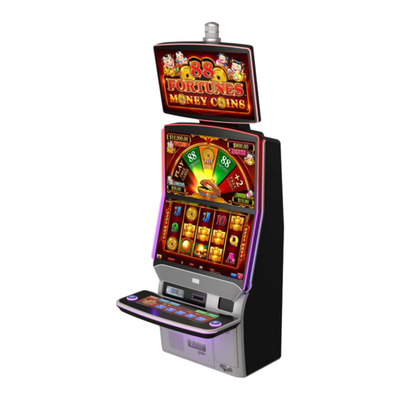
Cabinet Locks Chapter 1 Cabinet CAUTION Never remove or alter the cabinet serial number plate. Figure 1 Cabinet example Cabinet Locks The cabinet requires five to seven locks and a locking key switch to control access to the cabinet and specific machine components. -
Page 10: External Cabinet Lock Locations
Cabinet Locks Chapter 1 Cabinet External Cabinet Lock Locations The following figures show the locations of lock mechanisms and the Attendant key switch. Figure 2 External lock locations Table 1 External lock location legend Reference Description Main Door Locks (one or two) Lower (Belly) Door Locks (one or two) Cash Box Door Locks (one or two) Attendant Key Switch (one) - Page 11 Cabinet Locks Chapter 1 Cabinet Figure 4 Bill acceptor inner door Figure 5 Bill acceptor stacker © 2022 Light & Wonder, Inc. and its Subsidiaries. All rights reserved. CONFIDENTIAL Kascada™ (SK-1V227ST) Service Manual 1581413 [A] August 2022...
- Page 12 Cabinet Locks Chapter 1 Cabinet Figure 6 Lock assembly example Table 2 Lock assembly figure legend Callout Description Key, Shape May Vary 7 Pin Tumbler with Circular Key way and 3/4-Inch Diameter Body Barrel, Length May Vary Locked Position, Key Removable Counter Clockwise Rotation Locked Position Clockwise Rotation Locked Position Mounting Nut...
-
Page 13: Cabinet Troubleshooting
Cabinet Troubleshooting Chapter 1 Cabinet Cabinet Troubleshooting Cabinet Troubleshooting Flowchart Use the following flowchart to troubleshoot cabinet issues. Figure 7 Troubleshooting flowchart for the cabinet © 2022 Light & Wonder, Inc. and its Subsidiaries. All rights reserved. CONFIDENTIAL Kascada™ (SK-1V227ST) Service Manual 1581413 [A] August 2022... -
Page 14: Chapter 2 Bill Acceptor
Chapter 2 Bill Acceptor This chapter includes the following topics: Bill Acceptor Overview on page 14 Bill Acceptor Instructions on page 15 Bill Acceptor Troubleshooting on page 16 Bill Acceptor Overview A bill acceptor examines currency or tickets and communicates the value to the machine. A bill acceptor provides the ability to accept printed currency or tickets. -
Page 15: Bill Acceptor Instructions
Bill Acceptor Instructions Chapter 2 Bill Acceptor Bill Acceptor Instructions For optimal performance, keep the bill path, rollers, and belts clean. Use a soft lint-free cloth to clean the sensor lenses. Do not use any harsh solvent that will harm the transparent polymer material. To access the bill acceptor for maintenance, use the following steps. -
Page 16: Bill Acceptor Troubleshooting
Bill Acceptor Troubleshooting Chapter 2 Bill Acceptor Bill Acceptor Troubleshooting Figure 11 Bill acceptor troubleshooting flowchart © 2022 Light & Wonder, Inc. and its Subsidiaries. All rights reserved. CONFIDENTIAL Kascada™ (SK-1V227ST) Service Manual 1581413 [A] August 2022... -
Page 17: Chapter 3 Printer
Chapter 3 Printer This chapter includes the following topic: Printer Overview on page 17 Printer Overview A printer provides a machine the ability to create documents on thermal ticket stock. Typical documents created by a machine printer are vouchers, accounting statistics reports, diagnostic reports, and receipts for jackpots and other payments by Attendants. -
Page 18: Printer Troubleshooting Flowchart
Printer Overview Chapter 3 Printer Printer Troubleshooting Flowchart Use the following flowchart to troubleshoot printer issues. Figure 14 Printer troubleshooting flowchart © 2022 Light & Wonder, Inc. and its Subsidiaries. All rights reserved. CONFIDENTIAL Kascada™ (SK-1V227ST) Service Manual 1581413 [A] August 2022... -
Page 19: Chapter 4 Cpu Control System
Chapter 4 CPU Control System This chapter includes the following topics: CPU Overview on page 19 CPU Troubleshooting on page 20 CPU Overview The central-processing unit (CPU) is the hardware component that controls the machine. Figure 15 CPU control subsystem location Figure 16 CPU components ©... -
Page 20: Cpu Troubleshooting
CPU Troubleshooting Chapter 4 CPU Control System CPU Troubleshooting Codes Displayed by the CPU Table 3 Error codes Code Error Comment Three horizontal bars on the left digit BMC switched to low power mode, CPU Normal display when power is switched 6C/GC Missing PEG graphics card The graphics card may not be fully... -
Page 21: Why Is The Game Not Starting Up When The Power Is On
CPU Troubleshooting Chapter 4 CPU Control System Why is the game not starting up when the power is on? The CPU components may not be working correctly. Confirm the following: The 3.3V, 5V, 12V, and POWER GOOD power indicator LEDs illuminate when the machine power switch is on. ... -
Page 22: Cpu Control Subsystem Troubleshooting Flowchart
CPU Troubleshooting Chapter 4 CPU Control System CPU Control Subsystem Troubleshooting Flowchart Use the following flowchart to troubleshoot CPU issues: CAUTION To prevent damage to electronic components, always use appropriate electrostatic discharge (ESD) precautions. Use a wrist or ankle strap and ground all tools and equipment. -
Page 23: Chapter 5 Backplane Board
Chapter 5 Backplane Board This chapter provides the following information: Backplane Board Overview on page 23 Backplane Board Instructions on page 32 Backplane Troubleshooting on page 34 Backplane Board Overview The backplane board is the main signal and power interconnect between the CPU board and most cabinet components. The backplane board interfaces the CPU board with the remainder of the machine and distributes signals and power. - Page 24 Backplane Board Overview Chapter 5 Backplane Board The following is a representation of the backplane board. Figure 20 Backplane board © 2022 Light & Wonder, Inc. and its Subsidiaries. All rights reserved. CONFIDENTIAL Kascada™ (SK-1V227ST) Service Manual 1581413 [A] August 2022...
- Page 25 Backplane Board Overview Chapter 5 Backplane Board The following are the signals available at each backplane port connector. MPU Interface SIGNAL BOTTOM ROW TOP ROW DCM_POWER_GOOD PLAYER_BUTTON_LED0 DCM_POWER_ENABLE PLAYER_BUTTON_SW_0# CAB_POWER - NO LONGER USED BP_BMC_RESET_OUT# BP_I2C_DATA BP_I2C_CLK BOARDuC_SDA DOOR_SW0 BOARDuC_SCL Mechanical Key DOOR_SW1 DOOR_SW3...
- Page 26 Backplane Board Overview Chapter 5 Backplane Board POWER ENTRY/CONTROL DC-DC POWER MODULE - DCM EGM POWER SUPPLY INPUT PCB BOTTOM PCB TOP V_24V0 DC_PWR_MOD_SEATED V_24V0 V_24V0 C149 C150 C151 C152 C153 C154 10uF 100nF 220pF 10uF 10uF 10uF 100nF 100nF 100nF Header, Vertical, D/R V_12V0...
- Page 27 Backplane Board Overview Chapter 5 Backplane Board POWER DISTRIBUTION MONITOR POWER 1 MONITOR POWER 2 MONITOR POWER 3 V_24V0 V_24V0 V_24V0 100nF 10uF 10uF 100nF Header, MiniFit Jr, Vert, D/R 10uF 100nF 0039281043 Header, MiniFit Jr, Vert, D/R Molex 0039281043 Header, MiniFit Jr, Vert, D/R Molex 0039281043...
- Page 28 Backplane Board Overview Chapter 5 Backplane Board HARD METERS HARD_METER_5# HARD_METER_FAULT HARD_METER_4# HARD_METER_3# HARD_METER_PRESENT# HARD_METER_2# HARD METER PRESENT GND HARD_METER_1# V_12V0 HARD_METER_0# Header, Minifit Jr, Vert, D/R 10uF 100nF Molex 39-28-1123 HARD_METER_0# HARD_METER_1# HARD_METER_2# V_12V0 V_12V0 V_12V0 S1G-13-F S1G-13-F S1G-13-F 400V 400V 400V...
- Page 29 Backplane Board Overview Chapter 5 Backplane Board BV/CARD READER SERIAL PORT - SPARE1 SERIAL PORT - SPARE 2 V_5V0 SP9_CARD_READER_RS-232_RX SP9_CARD_READER_RS-232_TX SP12_SPARE2_RS-232_TX SP11_SPARE1_RS-232_TX 100nF 10uF SP12_SPARE2_RS-232_TX SP12_SPARE2_RS-232_RX SP11_SPARE1_RS-232_RX DOOR_SW3 SP12_SPARE2_RS-232_RX DOOR_SW1 BV_BEZEL_LED# Header, SL, 3 pos, Vert BV_LOCKOUT# BV_RESET# Header, SL, 3 pos, Vert 70543-0002 70543-0002 SP4_BILL_VAL_RS-232_TX...
- Page 30 Backplane Board Overview Chapter 5 Backplane Board USB 2.0 HUBS, PORTS 0-1, 4-9 4 PORT USB 2.0 HUB #1 4 PORT USB 2.0 HUB #2 Layout Note: Layout Note: USB 2.0 differential impedance = 90 ohms USB 2.0 differential impedance = 90 ohms +/- 15%, Single ended impedance = 45 ohms +/- 15%, Single ended impedance = 45 ohms +/- 10%.
- Page 31 Backplane Board Overview Chapter 5 Backplane Board USB 2.0 PORTS 2, 3, 10, 11 USB 2.0 AUDIO/ROOT - PORTS 2,3 V_5V0 C139 100nF USB_3_OC# OUT1 OUT2 USB_2_OC# STMPS2252MTR TVS7 C141 FB 100 Ohm 2A C143 120uF 20mOhm 100nF 0 Ohm USBLC6-2P6 497-5026-1-ND USB 2.0 RIGHT...
-
Page 32: Backplane Board Instructions
Backplane Board Instructions Chapter 5 Backplane Board Backplane Board Instructions Removing the Backplane Board from the Housing Follow these steps to remove the backplane board from the housing. Unlock and open the CPU door. Remove the CPU assembly. Disconnect all cables from the board. To remove the entire assembly, remove the remaining three screws shown in Figure Figure 21 Removing the backplane assembly... - Page 33 Backplane Board Instructions Chapter 5 Backplane Board Remove backplane board by removing the 13 Philips screws securing it to the backplane housing show in Figure Figure 23 Removing the screws Secure the new backplane board to the backplane housing with 13 screws. Reconnect the cables.
-
Page 34: Backplane Troubleshooting
Backplane Troubleshooting Chapter 5 Backplane Board Backplane Troubleshooting Backplane Board Troubleshooting Flowchart Use the following flowchart to troubleshoot backplane issues: CAUTION To prevent damage to electronic components, always use appropriate electrostatic discharge (ESD) precautions. Use a wrist or ankle strap and ground all tools and equipment. -
Page 35: Chapter 6 Power Supplies
Chapter 6 Power Supplies This chapter provides the following information: Power Supply Overview on page 35 Power Supply Instructions on page 37 Power Supply Troubleshooting on page 38 Power Supply Overview AC Power Module The machine receives power from a floor or wall outlet on a grounded circuit capable of sustaining the power requirements. -
Page 36: Dc Power Module
Power Supply Overview Chapter 6 Power Supplies DC Power Module The DC Power module supply converts the incoming AC power to DC required for machine components. It provides power to the CPU Board and other cabinet components through the backplane board. The location of the power supply is at the left of the backplane housing assembly. -
Page 37: Power Supply Instructions
Power Supply Instructions Chapter 6 Power Supplies Power Supply Instructions Replacing the AC Power Module Use the following instructions to replace the AC power module. Disconnect the power cord from the power module. Using a nut driver, remove the nut securing the top of the assembly and loosen the nut at the bottom until the assembly lifts free from the cabinet wall. -
Page 38: Power Supply Troubleshooting
Power Supply Troubleshooting Chapter 6 Power Supplies Power Supply Troubleshooting Power Supply Troubleshooting Flowchart CAUTION To prevent damage to electronic components, always use appropriate electrostatic discharge (ESD) precautions. Use a wrist or ankle strap and ground all tools and equipment. Use the following flowchart to troubleshoot power supply issues: Figure 31 Troubleshooting flowchart for the power supply ©... -
Page 39: Chapter 7 Deck
Chapter 7 Deck This chapter includes the following topics: Deck Overview on page 39 Deck Instructions on page 40 iDeck Troubleshooting on page 41 Deck Overview All machines provide an interactive touch-panel deck to accept input from the player for game play. The player touches the interactive deck to select the number of pay lines, make wagers, or choose other available options. -
Page 40: Deck Instructions
Deck Instructions Chapter 7 Deck Deck Instructions Removing the iDeck Monitor Use the following instructions to remove the iDeck monitor. Using a Phillips head screwdriver, remove 10 screws from the bottom of the iDeck. Figure 34 iDeck bottom view While holding the main door release, lift the iDeck monitor from the deck assembly. Disconnect the USB cable from the iDeck monitor. -
Page 41: Ideck Troubleshooting
iDeck Troubleshooting Chapter 7 Deck iDeck Troubleshooting Deck Troubleshooting Flowchart Use the following flowchart to troubleshoot deck issues Figure 36 Deck troubleshooting flowchart © 2022 Light & Wonder, Inc. and its Subsidiaries. All rights reserved. CONFIDENTIAL Kascada™ (SK-1V227ST) Service Manual 1581413 [A] August 2022... -
Page 42: Chapter 8 Monitors
Chapter 8 Monitors This chapter includes the following topics: Monitor Overview on page 42 Removing Monitors on page 44 Monitor Troubleshooting on page 45 NOTE Machine configurations may vary. See your cabinet manuals for parts specific to your machine. -
Page 43: Backplane Displayport Connectors
Monitor Overview Chapter 8 Monitors Backplane Displayport Connectors The following figures show the Displayport connectors. CAUTION Always refer to the label on the Salem MPU for the correct port order as new video card variants may have a alternate configuration than shown in Figure Figure 38 Displayport connections Figure 39 Alternate Displayport connections... -
Page 44: Removing Monitors
Removing Monitors Chapter 8 Monitors Removing Monitors Removing the Dual Monitors Use the following instruction to remove the primary and secondary monitors. Open the main door. Switch power OFF. Disconnect the power, touchscreen, bezel lighting, and video cables. Figure 40 Monitor connections Unfasten and remove the four nuts holding each display in place. -
Page 45: Monitor Troubleshooting
Monitor Troubleshooting Chapter 8 Monitors Monitor Troubleshooting Frequently Asked Questions (FAQ) Why is there no video when the power indicator LEDs are on? The video signal cable connections are incorrect. Ensure the video cables are connected correctly. Replace if necessary. Why is there no video when the cabinet power is on? If the cabinet and main power are on and the CPU power is on and nothing displays on the monitor, then the monitor cable connections are incorrect or disconnected. -
Page 46: Monitor Troubleshooting Flowchart
Monitor Troubleshooting Chapter 8 Monitors Monitor Troubleshooting Flowchart Use the following flowchart to troubleshoot monitor issues: CAUTION To prevent damage to electronic components, always use appropriate electrostatic discharge (ESD) precautions. Use a wrist or ankle strap and ground all tools and equipment. Figure 42 Troubleshooting flowchart for a monitor ©... -
Page 47: Chapter 9 Topper
Chapter 9 Topper This section provides the following information: Topper Overview on page 47 Topper Assembly Replacement Instructions on page 48 Topper Replacement Campaign on page 50 Topper Troubleshooting on page 50 NOTE Machine configurations may vary. See your cabinet manuals for parts specific to your machine. -
Page 48: Topper Assembly Replacement Instructions
Topper Assembly Replacement Instructions Chapter 9 Topper Topper Assembly Replacement Instructions Use the following instructions to replace the Kascada Dual topper assembly. Open the main door and switch power OFF. Ensure you can access the topper. If necessary, unbolt the EGM and use a ladder. Disconnect the V4 video cable from the main logic board. - Page 49 Topper Assembly Replacement Instructions Chapter 9 Topper CAUTION The following steps require two technicians. The topper unit is not hinged and must be held during removal and assembly. Ask the second technician to hold the front of the topper monitor. Unfasten six mounting nuts from the standoffs located under the topper from inside the main cabinet.
-
Page 50: Topper Replacement Campaign
Topper Replacement Campaign Chapter 9 Topper Topper Replacement Campaign For information regarding the topper replacement campaign, check technical bulletin 1585417. Topper Troubleshooting Topper Troubleshooting Flowchart Use the following flowchart to troubleshoot topper issues: CAUTION To prevent damage to electronic components, always use appropriate electrostatic discharge (ESD) precautions. -
Page 51: Chapter 10 Tower Light
Chapter 10 Tower Light This section provides the following information: Tower Light Overview on page 51 Tower Light Troubleshooting on page 53 NOTE Machine configurations may vary. See your cabinet manuals for parts specific to your machine. Tower Light Overview The tower light is a multi-level, tiered lamp with colored lenses. - Page 52 Tower Light Overview Chapter 10 Tower Light The following figure displays a super candle tower light assembly example: Figure 50 Super candle tower light assembly view © 2022 Light & Wonder, Inc. and its Subsidiaries. All rights reserved. CONFIDENTIAL Kascada™ (SK-1V227ST) Service Manual 1581413 [A] August 2022...
-
Page 53: Tower Light Troubleshooting
Tower Light Troubleshooting Chapter 10 Tower Light Tower Light Troubleshooting If the tower light does not illuminate, the following causes apply: failed LEDs or damaged or disconnected cables. Replace failed LEDs. Inspect and connect cables. Replace if necessary. Tower Light Troubleshooting Flowchart Use the following flowchart to troubleshoot tower light issues: CAUTION To prevent damage to electronic components, always use appropriate... -
Page 54: Appendix A Periodic Maintenance
Appendix A Periodic Maintenance This section provides the following information: Maintenance Schedule on page 54 Cabinet Periodic Maintenance on page 55 Cable Periodic Maintenance on page 55 Door and Key Switch Periodic Maintenance on page 56 Lock, Cam, and Key Periodic Maintenance on page 57 ... -
Page 55: Cabinet Periodic Maintenance
Cabinet Periodic Maintenance Appendix A Periodic Maintenance Cabinet Periodic Maintenance Use the following instructions to maintain the cabinet: Cabinet Interior Maintenance Maintenance Service Interval: 60 days Vacuum the inside of the cabinet. Remove all dust and debris from the bill and printer chutes. ... -
Page 56: Testing Cable Continuity Using A Continuity Tester (Or Multimeter)
Door and Key Switch Periodic Maintenance Appendix A Periodic Maintenance Testing Cable Continuity using a Continuity Tester (or Multimeter) Use the following instructions to test a cable for continuity: Switch on the continuity tester and adjust the controls as appropriate. Continuity testers may differ slightly. For a multimeter, adjust the controls to measure continuity or resistance (ohms). -
Page 57: Lock, Cam, And Key Periodic Maintenance
Lock, Cam, and Key Periodic Maintenance Appendix A Periodic Maintenance Lever switches connect to the cabinet or components with brackets, screws or nuts. Secure the switch to the cabinet, bracket, or component with screws or nuts. Figure 53 Lever switch example Key switches connect to the cabinet with nuts. -
Page 58: Cpu Periodic Maintenance
CPU Periodic Maintenance Appendix A Periodic Maintenance CPU Periodic Maintenance Use the following information to maintain the CPU: CPU Maintenance For detailed CPU information, see your Service Manual and User Guide. Power Supply Periodic Maintenance Use the following information to maintain the power supply: Power Supply Maintenance For information on power supply status LEDs on the CPU front panel, see page... -
Page 59: Bill Acceptor Periodic Maintenance
Bill Acceptor Periodic Maintenance Appendix A Periodic Maintenance Bill Acceptor Periodic Maintenance Use the following information to maintain the bill acceptor: Flash Media Maintenance Service Interval: 30 days Verify the flash media version is correct and is the latest revision. For example, there may be a newer version available for the changing currency. -
Page 60: Tower Light Periodic Maintenance
Tower Light Periodic Maintenance Appendix A Periodic Maintenance Tower Light Periodic Maintenance Use this information to maintain the tower light components: LEDs Maintenance Service Interval: As needed Replace any failed LEDs. Maintenance Before Storing Machine It is recommend to shut down power at the main power switch and to deactivate NVRAM jumpers when a machine is to be powered down for an extended period of time.
Need help?
Do you have a question about the Kascada SK-1V227ST and is the answer not in the manual?
Questions and answers
what are the dimensions of a kascada cabinet please both 2 screen and 3 screen? please