Table of Contents
Advertisement
Quick Links
User manual
This document refers to the following products:
907 910
Netsilon 9 AC
907 911
Netsilon 9 DC
907 912
Netsilon 9 AC+DC
907 913
Netsilon 9 AC+AC
This document refers to the following products:
907 915
Netsilon 11 AC
907 916
Netsilon 11 DC
907 917
Netsilon 11 AC+DC
907 918
Netsilon 11 AC+AC
www.bodet-time.com
On receipt, ensure that the product has not been damaged during transportation and report any concerns to
the carrier.
TIME SERVER
NETSILON 9 / 11
BODET Time & Sport
1 rue du Général de Gaulle
49340 TREMENTINES - France
Tél. support France: 02 41 71 72 99
Tel.: +33 (0) 2 41 71 72 33
1
Advertisement
Table of Contents

Summary of Contents for Bodet Time Time Server Netsilon 9
- Page 1 Netsilon 11 DC 907 917 Netsilon 11 AC+DC 907 918 Netsilon 11 AC+AC BODET Time & Sport 1 rue du Général de Gaulle 49340 TREMENTINES - France Tél. support France: 02 41 71 72 99 www.bodet-time.com Tel.: +33 (0) 2 41 71 72 33 On receipt, ensure that the product has not been damaged during transportation and report any concerns to the carrier.
-
Page 2: Table Of Contents
TABLE OF CONTENTS SAFETY INFORMATION 1. GENERAL INFORMATION 1.1 Use of the instructions 1.2 Introduction 1.3 Netsilon presentation 1.3.1. Front panel 1.3.2. Rear panel 1.4 Specifications 1.4.1. Accuracy 1.4.2. Connections for time synchronisation and broadcasting 1.4.3. Mechanical characteristics 1.4.4. Electrical characteristics 1.4.5. - Page 3 3. COMMISSIONING 3.1 Factory configuration 3.2 Choosing the LCD screen display language 3.3 Choosing the network interface 3.4 Configuration with a DHCP server 3.5 Configuration without a DHCP server 4. CONFIGURATION VIA WEB SERVER 4.1 Start-up 4.1.1. Presentation of the main menu 4.1.2. Configuring the Netsilon front panel 4.1.3. Changing the language 4.2 Managing users 4.2.1. Local management 4.2.1.1 Changing the password 4.2.1.2 Creating or modifying an account 4.2.1.3 Deleting an account...
- Page 4 4.5 Choosing synchronisation sources 4.5.1. Status of sources 4.5.2. Priority of sources 4.5.3. Satellite receivers 4.5.4. Jamming and spoofing of GNSS signals 4.5.5. IRIG INPUT option card (ref. 907 947) 4.6 NTP 4.6.1. NTP service 4.6.2. NTP client 4.6.3. NTP servers 4.6.4. NTP peers 4.6.5. NTP key 4.6.6. NTP Autokey 4.6.7.
- Page 5 4.10.4. Importing public keys 4.11 System supervision 4.11.1. SNMP agent 4.12 System monitoring 4.12.1 Homepage 4.12.2. GNSS statistics 4.12.3. NTP statistics 4.12.4. PTP statistics 4.12.5. IRIG statistics 4.12.6. Oscillator statistics 4.12.7. NTP log 4.12.8. Syslog log 4.12.9. Alarm history 4.13 System tools 4.13.1. Firmware update 4.13.2. Loading and saving a configuration 4.13.3.
- Page 6 7.1.3. USB transfer menu 7.2 Technician menu 8. SUPPORT 8.1 Status of LEDs on the front panel 8.2 Impossibility to open the web browser 8.3 Inactive control panel 8.4 Data synchronisation 8.5 USB loading 8.6 BODET technical support 8.7 Update history of this user manual 9.
-
Page 7: Safety Information
SAFETY INFORMATION The following icons are used to indicate risks or sources of danger when installing, using and maintaining this product. Symbol Description IEC60417 - 1641 Operating instructions IEC60417 - 5002 Positioning of cell IEC60417 - 5017 Class I IEC60417 - 5018 Functional earthing IEC60417 - 5019 Protective earth (ground) -
Page 8: General Information
1. GENERAL INFORMATION Thank you for choosing the BODET Netsilon 9 / 11 time server. This product has been carefully designed for your satisfaction, according to the rules of our ISO9001 and ISO14001 quality system. We recommend that you read this manual carefully before using the product for the first time. Retain this manual throughout the lifespan of your product so that you can refer to it when necessary. -
Page 9: Netsilon Presentation
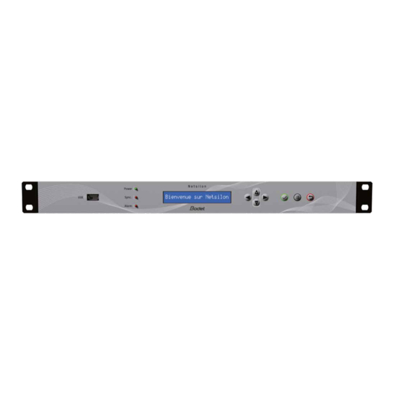
1.3 Netsilon presentation 1.3.1. Front panel The Netsilon front panel contains: > a USB port > three status LEDs for power supply, synchronisation and alarms (Power, Sync and Alarm) See chapter 8.1 Status of LEDs on the front panel > a two-line LCD display >... - Page 10 Common/Normally-Closed/Normally-Open relay contact output. If contact Normally-Open: no alarms / if contact Normally-Closed: alarms. SLOT A SLOT B SLOT C SLOT D GNSS ETH0 ANTENNA ALARM OUT ALARM IN 10 MHz MADE IN FRANCE Alarms input: interfaces with the dry contact of the client equipment. SLOT A SLOT B SLOT C...
-
Page 11: Specifications
1.4 Specifications 1.4.1. Accuracy Typical values - Netsilon 9 Typical values - Netsilon 11 Accuracy 1x10 1x10 Stability 1x10 /day 1x10 /day Holdover 15 µs (after 24 hours) 2.5 µs (after 24 hours) average after 24 hours with GPS signal average after 2 weeks with GPS signal typical value, after a 2-week GPS synchronisation at constant temperature 1.4.2. Connections for time synchronisation and broadcasting Standard Option GNSS Inputs IRIG Outputs 10 MHz... -
Page 12: Network Characteristics
Two synchronisation sources are available for the Netsilon 9 / 11: the BODET GNSS antenna or an NTP server present on the computer network. NTP Synchronisation GNSS Synchronisation SATELLITES GNSS antenna (Bodet) GPS antenna Time Server Netsilon 9 / 11 NTP Server (Client equipment) Time Server Netsilon 9 / 11 1PPS Other equipment ALERT Ethernet... -
Page 13: Installation
2. INSTALLATION This chapter provides an overview of the steps to be followed to install a Netsilon 9 or Netsilon 11. Several factors must be taken into account when installing Netsilon 9 / 11: 1) The type of power supply: AC, DC, AC+DC, AC+AC 2) The type of installation: integration of a Netsilon 9 / 11 into an existing Ethernet network or new installation (ensure cable accessibility). -
Page 14: Electrical Installation
2.4 Electrical installation All cables must be securely attached to the chassis before being connected to the various terminal blocks in order to prevent traction on connections. Furthermore, conductors on the same circuit must be attached to each other close to the terminal block to avoid reduced isolation should one of the terminals become loose. -
Page 15: Commissioning
3. COMMISSIONING Netsilon configuration is performed exclusively on the web server. In order to be able to access the web server, it is necessary to configure the ETH0 port via the front panel keypad and the LCD screen. In order not to disrupt Netsilon synchronisation with the other products present on the network, it is important to maintain identification of the time server. -
Page 16: Choosing The Lcd Screen Display Language
3.2 Choosing the LCD screen display language The network settings for configuration of the ETH0 port (assignment of an IP address) can be read or configured via the Netsilon control panel. It is necessary to first select the product’s display language: 10:54.32 Mon 19 SEPT 20__ System... -
Page 17: Configuration With A Dhcp Server
3.4 Configuration with a DHCP server 1) On start up, the Netsilon 9 / 11 time server waits for automatic assignment of an IP address by the DHCP server. This may take a few minutes. 2) Once assigned, this IP address is shown on the LCD screen. By default, the LCD screen alternately displays several settings. -
Page 18: Configuration Without A Dhcp Server
3.5 Configuration without a DHCP server Without automatic assignment of an IP address by a DHCP server, it is necessary to manually assign a fixed IP address. To manually configure the Netsilon network settings, enter the following three parameters: > IP address assignment > This is a unique address assigned to Netsilon by the network administrator. Ensure that the chosen address is available. -
Page 19: Configuration Via Web Server
4. CONFIGURATION VIA WEB SERVER The order of the chapters corresponds to the steps to be completed as part of an initial commissioning. It is important to observe this order to ensure correct deployment of the system. An administrator profile is required to modify the web server parameters presented in this chapter. To view rights according to the profile used, please refer to Annex 3: rights according to profile. - Page 20 2) Click on , the following window will appear: 3) Perform the desired configuration: Can be used to lock the Netsilon control panel when the box is checked. This function can be used to prevent any misuse by a third party. >...
-
Page 21: Changing The Language
4.1.3. Changing the language To make the configuration easier, it is recommended to select the language you are the most comfortable with: To choose the web server display language, follow these steps: 1) SYSTEM menu > General > Settings: Modify the domain name of the time server Modify the language of the web server and the idle... -
Page 22: Creating Or Modifying An Account
4.2.1.2 Creating or modifying an account To create a new account, follow these steps: 1) SECURITY menu > User management > Local users 2) Click on to add an account, and the following window will appear: Enter a username between 5 and 32 characters Select a profile type Enter a password between 7 and 32 characters 3) Click on... -
Page 23: Centralised Management
4.2.2. Centralised management 4.2.2.1 RADIUS service RADIUS authentication (Remote Authentication Dial-In User Service) implies the use of an external server allowing centralised management of users to log in to Netsilon. The login password entered by the user is stored in a RADIUS server on the network. - Page 24 2) To make the settings, click on , and the following window will appear: 3) Fill in the various fields to configure the settings: Tab - General Base DN (Distinguished Name): enter the name of the search base containing the server directories to be queried for an authentication match.
- Page 25 Tab - Mapping / Options If one or several variables do not exist in your LDAP server database in the user account section, the connections will be impossible. However, it is possible to map the following variables “Login uid attribute”, “uidNumber” and “gidNumber” to other variables. Variable corresponding to the login attribute used during the connection.
- Page 26 4) Add an LDAP server by clicking on , and the following window will appear: (Possibility to add up to five servers maximum) Enter the IP address or host name of the LDAP server. For certificate validation, it is mandatory to indicate the full host name of the LDAP server. It is strongly recommended to use different user names between those used via the LDAP server and those used locally. Do not duplicate users (declaration of local accounts in LDAP and vice versa). 5) Click on to view the certificate information that may have been imported from the certificate menu and on configure certificates and keys...
-
Page 27: Configuring The Time Zone
4.3 Configuring the time zone The time zone section enables centralised time zone creation and time scale management. Each output can be defined in a time zone, defined earlier in this chapter. 4.3.1. Defining the local time system and date The local time should only be changed when replacing the CR2032 battery. For the local time system and date, follow these steps: 1) TIME menu >... -
Page 28: Creating A Time Zone Manually
4.3.2. Creating a time zone manually To create a time zone, follow these steps: 1) TIME menu > Time zone > Time zones. The UTC reference is present by default. 2) Click on to create a zone, then tick Manual, and the following window will appear: Enter the name of the time zone. -
Page 29: Programming A Manual Leap Second
UTC+04:00 ABU DHABI UTC+05:30 CALCUTTA UTC+07:00 BANGKOK UTC+08:00 SINGAPORE UTC+09:00 TOKYO UTC+09:30 ADELAIDE UTC+10:00 SYDNEY UTC+11:00 NOUMEA Time changes are indicated in accordance with the chosen time zone. It is possible to create up to 20 time zones (including UTC). The UTC time zone cannot be deleted. 4.3.4. Programming a manual Leap Second If the programming of a Leap Second is planned and if Netsilon is synchronised from a source that does not manage this information (e.g IRIG synchronisation), then it must be entered manually in Netsilon. -
Page 30: Set Tai / Utc Offset
4.3.5. Set TAI / UTC offset If the synchronisation source used does not provide the Leap Second information (e.g: IRIG) and if Netsilon broadcasts in TAI, this value must be entered manually in Netsilon. The TAI/UTC offset is particularly dedicated to the particular case of IRIG synchronisation when Netsilon is also PTP master (see chapter 4.5.5 IRIG INPUT option card). To manually enter the TAI/UTC offset, follow these steps: 1) TIME menu > Time zone > TAI to UTC offset 2) Click on to configure the offset management, and the following window will appear: Define the offset mode: automatic/manual. -
Page 31: Configuring The Computer Network
4.4 Configuring the computer network 1) Click on the NETWORK to configure the network interfaces. As for network interface configuration, navigation is interactive: move the mouse over the connector of the interface to be configured, then click on it: Slot A Slot B Slot C Slot D 4.4.1. Network interface configuration To configure a network interface, follow these steps:... - Page 32 Enter the address of the primary DNS in order to assign a domain name. Enter the domain name extension in order to access the product’s web server from the DNS. e.g: if the name of the product is “Netsilon” (see chapter 4.1 Start-up) Example of access to the web server using the domain name: https://netsilon.test.local IPv6 settings:...
- Page 33 Bonding (Ethernet redundancy): The bounding allows to link several network interfaces (at least one Network option card must be available in Netsilon) to a group called "bond". This port redundancy provides security in the event of a network interface failure, as the time server remains accessible and available via one or several other interfaces from the group (bond). Two operating modes are available for each bond.
- Page 34 VLAN (virtual local area network): VLANs reinforce computer security of networks by providing logical segmentation inside an extensive physical network. Each VLAN has its own broadcast domain. Netsilon uses “VLAN tagged” with an assignment to the virtual local networks via the use of a tag in the message packet frame.
- Page 35 The following diagram summarises the frames exchanged during the authentication process: Switch RADIUS Server Supplicant (authenticator) (authentication server) EAP (start) EAP (request identity) EAP (response identity) RADIUS (access-request) RADIUS (access-challenge) EAP (request authentication) EAP (response authentication) RADIUS (access-request) RADIUS (access-accept) EAP (success) RADIUS (access-reject) EAP (failure)
- Page 36 2) Click on , the following window opens: 3) Activate the 802.1x protocol by checking the activation box, then choose the authentication protocol type: The “Authentication” field refers to the protocol used to secure the 802.1x connection between the supplicant and the authenticator and identify the supplicant using its identity or user name. 4) Set the parameters according to the chosen authentication protocol: - PWD: authentication by password.
- Page 37 - TTLS: authentication by encapsulating a TLS session in 2 phases: authentication of the server to the device (supplicant) through the use of a certificate to create a secure TLS tunnel for data exchange between the 2 parties during the second phase. During the second phase, the client is authenticated to the server using an internal authentication mechanism (PAP, MSCHAPv2...), through the secure tunnel.
- Page 38 - FAST: authentication via a secure TLS tunnel using a Protected Access Credential (PAC) dynamically generated by the authentication server. Enter the user name of the supplicant (Netsilon). Enter the password. This will be verified by the authentication server. To protect the user name of the supplicant (Netsilon) during the first identification phase, when the connection between Netsilon and the switch (authenticator) is not yet secured by the TLS tunnel, an “Anonymous identity”...
-
Page 39: Configuration Of Ipv4/Ipv6 Static Routes
4.4.2. Configuration of IPv4/IPv6 static routes To configure static routes: 1) NETWORK menu > Routes 2) Click on and a window will appear, then fill in the various parameters required to configure the routing: - Destination networks, - Subnet mask (or prefix for IPv6), - Gateway. - Page 40 > HTTP - HTTPS HTTPS (Hypertext Transfer Protocol Secure) is a communication protocol used to access a secure web server. If HTTPS is included in the URL instead of the usual HTTP, the message will be sent to a secure entry port on the server.
- Page 41 3) Go to the browser’s advanced settings, then click on “proceed to netsilon.be.local”: T he connection is secure, even if “https” is crossed and in red. This warning only indicates that the certificate has not been authenticated by a certified organisation. B odet recommends the use of the “https” mode to optimise security when accessing the Netsilon web server. > DNS The DNS (Domain Name System) is a protocol which can be used to associate a domain name, known as Hostname (e.g.
- Page 42 Activation of the SSH service Authentication by: - Only password: authentication by password only - Only public key: authentication by public key only. - Public key or password: authentication by password or public key. Types of keys supported: - RSA: 1024/ 2048/4096 bits - DSA: 1024 bits (fixed) - ECDSA: 256/384/521 bits - ED25519: 256 bits (fixed)
- Page 43 > SMTP SMTP (Simple Mail Transfer Protocol) is used to transfer electronic messages (alarms) in a computer network. An SMTP server is a service which listens on port 25. Its primary purpose is to route emails to a recipient. Click on Configure then refer to chapter 4.9.1 SMTP configuration.
-
Page 44: Choosing Synchronisation Sources
4.5 Choosing synchronisation sources To choose the synchronisation source(s), follow these steps: 1) TIME menu > Synchronisation 4.5.1. Status of sources An overview is provided. This area shows if the available synchronisation sources have been activated. 4.5.2. Priority of sources The priority of synchronisation sources can be used to define the priorities between each available source, in order to enable Netsilon to transmit a continuous, accurate time signal. -
Page 45: Satellite Receivers
4.5.3. Satellite receivers Enable GNSS synchronisation using the button. 1) Click on to select the type of antenna and the constellation(s). The button lists the authorised GNSS combinations. Choice of the type of antenna: GNSS or Secure GNSS (anti-jamming and anti-spoofing); If the GNSS secure antenna is chosen, an option is provided to exclude GNSS synchronisation in the event of spoofing detection. - Page 46 “Reset position” is only accessible in “time mode” and is used to restart the “survey” procedure to automatically determine the position of the antenna (e.g. if the position of the antenna has been altered). "Reset receiver” is used to restart the GNSS receiver if required. 1) To set the alarm threshold, click on the link Configure alarm thresholds, and the following window will...
-
Page 47: Jamming And Spoofing Of Gnss Signals
4.5.4. Jamming and spoofing of GNSS signals GNSS satellites operate from the Earth’s orbit. The transmitted signal is extremely weak when it reaches the earth’s surface. This low signal strength near the receivers makes the use of GNSS signals sensitive to intentional (malicious) or unintentional interference. There are mainly 2 types of interference: spoofing and jamming. - Page 48 2 time servers installed on 2 different sites synchronise together (via NTP, PTP or IRIG) over a private network (VPN) This option assumes that the 2 Bodet time servers are in automatic mode (choice of the source) and have 3 independent synchronisation sources each.
-
Page 49: Irig Input Option Card (Ref. 907 947)
4.5.5. IRIG INPUT option card (ref. 907 947) The IRIG INPUT option card makes it possible to synchronise Netsilon from an IRIG signal. To set up the IRIG input, follow these steps: 1) TIME menu > Synchronisation > IRIG 2) Enable the synchronisation using the button. - Page 50 (1) 100 Hz (2) 1 kHz (3) 10 kHz (4) 100 kHz Choose the coded expression. It depends directly on the format and the type of modulation previously chosen. This defines the data structure in the IRIG signal. Coded expressions (0) BCD TOY, Ctrl Func, Binary Seconds (1) BCD TOY, Ctrl Func (2) BCD TOY...
-
Page 51: Ntp
4.6 NTP 4.6.1. NTP service To enable the NTP service, proceed as follows: 1) TIME menu > NTP > NTP service Service ON/OFF button. Check this box to query the NTP server remotely. Authorisation of mode 6 and 7 NTP packets (remote information queries). -
Page 52: Ntp Client
4.6.2. NTP client In client mode: Netsilon synchronises on an NTP server in unicast. To add an NTP synchronisation source, follow these steps: 1) TIME menu > NTP > NTP client: 2) Add an NTP server by clicking on , and the following window will appear: (Possibility to add up to 10 servers maximum.) Enter the IP address (or the hostname) of the NTP server. -
Page 53: Ntp Servers
4.6.3. NTP servers In server mode: Netsilon broadcasts the time in multicast, broadcast or unicast. To enable the NTP Servers mode, follow these steps: 1) TIME menu > NTP > NTP servers: 2) Select the communication mode: multicast or broadcast. 3) Add an NTP server by clicking on , and the following window will appear: (Possibility to add up to 5 servers in multicast and broadcast) -
Page 54: Ntp Peers
4.6.4. NTP peers NTP peer is defined between two or more time servers. If neither of them is authorised (at the same hierarchical level) to know the time, both will work to obtain an identical synchronisation. Scenario 1: the reference server transmits the time signal SATELLITES GNSS Antenna Reference NTP server... - Page 55 To enable the NTP Peers mode, follow these steps: 1) TIME menu > NTP > NTP peers: 2) Add an NTP server by clicking on , and the following window appears: (Possibility to add up to five servers maximum) Enter the IP address of the NTP client. Poll interval: this is the period of time in seconds between two queries.
-
Page 56: Ntp Key
4.6.5. NTP key The NTP key enables secure communication between a server and an NTP client in order to prevent intrusion by a third-party server. SATELLITES NTP Key : Reference server Trusted enabled Symmetric Key ID: 12345 Digest scheme: MD5 Secure NTP information Key string Netsilon 9 / 11 Netsilon 9 / 11... - Page 57 Choose the authentication from the following list: - MD5 - SHA - SHA1 - MDC2 - RMD160 - MD4 Enter a key between 1 and 16 characters (speical and non-alphabetic characters not allowed. E.g.: !, $, #, %)
-
Page 58: Ntp Autokey
4.6.6. NTP Autokey Server (Trusted) Certificate Certificate generated by the server Private authentication Public authentication Client Copy and paste the public certificate into the client Autokey parameters. Remember that the devices must have different host names. To enable the NTP autokey mode, follow these steps: 1) TIME menu >... -
Page 59: Ntp Anycast
4.6.7. NTP Anycast Anycast is applied to the NTP protocol to establish reliable communication between the client and the server (server redundancy). The network (router / switch) must support the OSPF protocol. The clocks (clients) send a query to the servers. The Anycast OSPF switch will select the server that responds fastest in order to pass the information on to the clients. -
Page 60: Time Distribution
4.7 Time distribution Time distribution can be carried out in several ways: - NTP by using the Ethernet RJ45 and/or Ethernet SFP option cards, - PTP, - IRIG. Option cards can be selected in two ways: - In dynamic mode: hover the mouse over the desired option card, then click. The menu dedicated to this option card is shown on the screen. -
Page 61: Ptp Option Card (Ref: 907 922)
4.7.2. PTP option card (ref: 907 922) PTP (Precision Time Protocol - IEEE1588) is an Ethernet protocol that achieves a high level of time accuracy in the nanosecond range. Unlike NTP, PTP uses the physical layer to achieve this level of accuracy by time-stamping and transmitting the time stamp when sending frames over the network. - Page 62 To ensure a high level of accuracy on a network carrying PTP frames, specific switches must be used. There are two types of switches: The Boundary Clock (BC) which synchronises with the Master Clock (thus becoming its Slave) but becomes >...
- Page 63 3) Click on , and the following window will appear: PTP Profile: choose the “PTP profile” which will define: > The algorithm parameters for choosing the best Master Clock on the network (BMCA), > Parameters for configuring and sending data frames, >...
- Page 64 (End-to-end) and Default PTP (Peer-to-Per) profiles since there are two different mechanisms for measuring the delay period of a message. >E2E: the packet delay time is directly determined by an exchange of direct requests over the network from the Master to the Slaves. >P2P: The packet delay time is determined between two consecutive network elements (switch...) and then successfully added together to give the total delay time from the Master to the Slaves.
- Page 65 4) Setting up the PTP Network: Operating in IPv4: fixed IP configuration or DHCP service Operating in IPv6: local link address (with IPv4 address: fixed IP or DHCP service enabled) VLAN tagging support: optimised traffic management (VLAN ID + priority index). 5) Configure PTP SyncE.
-
Page 66: Irig Output Option Card (Ref: 907 930)
6) Setting up the Frequency output. - The SMA frequency output is always linked to the master. o Master mode: the frequency and the phase of the 1pps are the image of the Netsilon time zone. o Slave mode: the frequency and the phase of the 1pps are the image of the master’s Time zone to which the option is synchronised. - Page 67 Choose the output format: IRIG A/B/E/G, AFNOR 87500. The IRIG formats are defined by different pulse rates. Format Pulse rate Interval IRIG A 1000 PPS 1 ms IRIG B 100 PPS 10 ms IRIG E 10 PPS 100 ms IRIG G 10000 PPS 0.1 ms Choose the type of modulation of the output signal:...
-
Page 68: 1Pps And 10 Mhz Outputs
4.8 1PPS and 10 MHz outputs 4.8.1 1PPS output The 1PPS output on the BNC connector emits one high-precision pulse per second. 1) TIME menu > Outputs > Mouse pointer on the 1PPS output: To set up the 1PPS output, click on . The following window is displayed: Activation: - Always (by default) - Sync or Holdover - Sync... -
Page 69: 10 Mhz Output
4.8.2 10 MHz output The 10 MHz output on the BNC connector emits a 10 MHz sinusoidal signal. The 1PPS output and the 10 MHz output are linked. 1) TIME menu > Outputs > Mouse pointer on the 10 MHz output: Click on to set up the 10 MHz output. -
Page 70: Management Of Notifications
4.9 Management of notifications 4.9.1. SMTP configuration To register an SMTP server in order to send emails, follow these steps: 1) NOTIFICATION menu > SMTP: Click on to test the service directly (without having to generate a fault on the device). 2) In SMTP - service, click on , and the following window will appear: Enter the IP address of the receiving server (50 characters max.) Enter the communication port. -
Page 71: Snmp Trap Configuration
2) Enter the list of recipients: (5 recipients max). 3) Click on to add the e-mail address: (50 characters max) 4) Enable the service using the button, then save. 4.9.2. SNMP trap configuration To configure trap reception, follow these steps: 1) NOTIFICATION menu > SNMP Trap: Click on to test the service directly (without having to generate a fault on the device). -
Page 72: Configuration Of Alarms
Select the supported SNMP version: V1, V2C or V3. Enter a community name between 5 and 32 characters with no spaces. Enter the IP address of the trap destination server. 3) Click on 4) Enable the service using the button, then save. Version V3: (5 accounts maximum) 1 3 4... -
Page 73: Syslog Configuration
Check the box to enable alarm selection. Check the box for the alarm to be identified by the LED on the front panel of Netsilon and notified via a relay contact. Check the box for the alarm to be sent by e-mail (please refer to chapter 4.9.1 SMTP configuration). Check the box for the alarm to be sent in trap format (please refer to chapter 4.9.2 SNMP trap configuration). - Page 74 Choose a category for the type of message / system that caused the event (Free local use). For “Auth”, the facility option is not adjustable since it is standardised by the Syslog protocol. Choose the severity index of the message. Check to enable log local storage.
-
Page 75: Certificate And Key Management
4.10 Certificate and key management This menu allows importation of certificates and public keys in Netsilon. 4.10.1. Importing CA certificates To add CA certificates: 1) SECURITY menu > Certificates and keys > CA certificates 2) Click on , a window opens: Enter a certificate name (16 characters maximum). Select the use cases of the certificate: Syslog, LDAP, 802.1x (TLS, TTLS, PEAP). -
Page 76: Importing Signed Certificates
4.10.2. Importing signed certificates To add signed certificates: 1) SECURITY menu > Certificates and keys > Signed certificates To import signed certificates, a Certificate Signing Request (CSR) is required beforehand. This CSR must be signed by the Certification Authority. Then, the signed certificate can be imported into Netsilon. It is not possible to import a private key directly. -
Page 77: Certificate Expiration (Ca And Signed Certificates)
The certificates must be in X.509 Base64 format. As a reminder, a X.509 format certificate begins with «---BEGIN CERTIFICATE---» and ends with «---END CERTIFICATE---». The number of signed certificates is limited to 20. 5) Click on to see the information of the imported certificate. 4.10.3. Certificate expiration (CA and signed certificates) It is possible to set an alarm to inform of upcoming certificate expiry. 1) NOTIFICATION menu >... -
Page 78: System Supervision
4.11 System supervision 4.11.1. SNMP agent > ENABLING THE SNMP AGENT (EXAMPLE V1) 1) SECURITY menu > SNMP agent: 2) Click on , the following window will appear: Select the SNMP version. Enter a community name between 5 and 32 characters with no spaces. Choose the IP communication version: IPV4. Enter the IP address of the server. -
Page 79: System Monitoring
4.12 System monitoring 4.12.1 Homepage The homepage is a consultation page: This menu displays the current synchronisation status: The current synchronisation status and the synchronisation source used: > > Green = synchronisation OK > Red = no synchronisation. The stratum level: level in relation to the synchronisation source (satellite). >... -
Page 80: Gnss Statistics
4.12.2. GNSS statistics To see the Netsilon GNSS synchronisation statistics, follow these steps: 1) HISTORY menu > GNSS statistics 2) Select the date using the drop-down menu: The status of the GNSS reception is symbolised by two status levels: 0: GPS reception frame but no synchronisation (waiting period to check if the source is reliable). >... -
Page 81: Ntp Statistics
4.12.3. NTP statistics To see Netsilon NTP synchronisation statistics, follow these steps: 1) HISTORY menu > NTP statistics 2) Select the date using the “Date” drop-down menu: Time offset: time offset in relation to the reference synchronisation source. Drift compensation: gradual correction of the Netsilon oscillator in relation to the source. The idea is to move closer to the synchronisation source in a gradual manner (without any time jump). -
Page 82: Irig Statistics
4.12.5. IRIG statistics To see Netsilon IRIG synchronisation statistics, follow these steps: 1) HISTORY menu > IRIG statistics 4.12.6. Oscillator statistics To see the Netsilon oscillator statistics, follow these steps; 1) HISTORY menu > Oscillator statistics When the product starts up, the oscillator is in Freerun status (as if it had never been slaved). Then, it searches for the PPS signal to slave itself and switches to the Tracking status (tracking the PPS signal). Once it has been successfully slaved to the PPS, the oscillator locks on this signal (Locked status). If the PPS signal is lost, it switches to the Holdover status, then to the Freerun status when its own time zone is not longer reliable enough. -
Page 83: Ntp Log
4.12.7. NTP log To see the Netsilon log records, proceed as follows: 1) HISTORY Menu > NTP logs: This log contains saved information. It is a standard log generated by the NTP protocol. It is possible to perform a search on this log using the search bar. 4.12.8. -
Page 84: Alarm History
4.12.9. Alarm history To see the history of alarms and acknowledge them, follow these steps: 1) HISTORY menu > Alarms: > To refresh this list, click on There are two ways to acknowledge the alarms: > - individually by selecting the alarm to be acknowledged and clicking on - all alarms at once by clicking on Confirm by clicking on “Yes”... -
Page 85: System Tools
4.13 System tools 4.13.1. Firmware update To update the Netsilon firmware, follow these steps: 1) SYSTEM menu > Tools > Update and backup. 2) Click on , and the following window will appear to select the file to import: The latest version of the firmware is available at www.bodet-time.com 4.13.2. Loading and saving a configuration To save a configuration, follow these steps: 1) SYSTEM menu >... -
Page 86: Firmware Version And Online Help
4.13.3. Firmware version and online help To see the firmware version of Netsilon and the option cards, proceed as follows: 1) SYSTEM menu > General > Versions: To access the product user manual, proceed as follows: 1) SYSTEM menu > General > Online help: 4.13.4. -
Page 87: Removing An Option Card
4.13.7. Removing an option card If an option card is physically removed from Netsilon, it must also be removed from the web server so as not to generate false alarms. To remove an option card from the Netsilon software, follow these steps: 1) SYSTEM menu >... -
Page 88: Configuration By Ssh
5. CONFIGURATION BY SSH > To access the SSH online command set interface, follow these steps (Netsilon must be connected to the network via its ETH0 port) : 5.1 Authentication by password 1) Download a program enabling you to log into Netsilon remotely (e.g.: PuTTY). 2) Provide the Netsilon IP address. -
Page 89: Authentication By Public Key
5.2 Authentication by public key 1) Download a program that will generate public/private keys (e.g.: PuTTY Key Generator). 2) Generate a public/private key by clicking on Hover your PC mouse over this space to generate the key 3) Save the public key in a file (.txt type) to be imported in the Certificates and keys menu of Netsilon in the “public keys”... - Page 90 5) Download a program enabling the connection (e.g: PuTTY). 6) Open the program (PuTTY). 7) Enter the IP address of Netsilon: 8) Enter the location on your PC containing the private key matching the public key imported to Netsilon: 9) Enter the user: 10) Click on the following window opens:...
-
Page 91: Configuration By Console
6. CONFIGURATION BY CONSOLE > To access the Netsilon web server, follow these steps (Netsilon must be connected to the PC via its COM serial port). T he physical connection between the PC and Netsilon must be provided by an RS232 (DB9) male/ female serial cable. -
Page 92: Configuration By Control Panel
7. CONFIGURATION BY CONTROL PANEL 7.1 Main menu tree Configuration of menus via the control panel provides for basic settings. Advanced settings are configured via the web server. Menus are automatically closed after 45 seconds of inactivity on the control panel. 10:54.32 Tues 19 SEPT 20__ System ok See chapter 7.1.1 System menu Network õ Network ok See chapter 7.1.2 Network menu USB transfer õ... -
Page 93: System Menu
7.1.1. System menu This menu can be used to see the following parameters: > the product’s MAC address, > the name of the product and its firmware version, > the option card(s) installed, > the language used for the menus displayed on the LCD screen. 10:54.32 Tues 19 SEPT 20__ System... -
Page 94: Network Menu
7.1.2. Network menu This menu can be used to see, define and configure the parameters of the ETH0 network port only. 10:54.32 Tues 19 SEPT 20__ System ok Network õ Network ok USB transfer õ 192.168.1.0/24 With DHCP server Display eth0 ok No gateway ok Config. eth0 õ No IP address Without DHCP server No gateway ok... -
Page 95: Usb Transfer Menu
7.1.3. USB transfer menu The Netsilon time server can load or save its programming via a USB key. Before creating any new programming, it is necessary to save the existing one on a USB key. 10:54.32 Tues 19 SEPT 20__ System ok Network õ... -
Page 96: Technician Menu
7.2 Technician menu This menu is only accessible with a technician code. This daily code is held by BODET. To obtain this code, contact BODET customer support and ensure that you have the MAC address of the ETH0 network output. In this menu, it is possible to: >... -
Page 97: Support
8. SUPPORT 8.1 Status of LEDs on the front panel The LEDs can provide Netsilon status information. Status and Description Check that... colour 1) The mains (AC) power supply cable is connected to a Netsilon connector and the No power supply power switch is ON. -
Page 98: Impossibility To Open The Web Browser
8.2 Impossibility to open the web browser > With DHCP server Check that the DHCP server delivers the IP address: the IP address is displayed on the Netsilon LCD screen (see chapter 3.4 Configuration with a DHCP server) > Without DHCP server: fixed IP address Check that the network settings are correct: IP address available, subnet mask, gateway... -
Page 99: Data Synchronisation
8.4 Data synchronisation To configure Netsilon via the web server, several parameters must be observed: > The PC must be on the same network as Netsilon. Make sure that a web browser is installed on the PC (Google Chrome®, Mozilla Firefox, Microsoft Edge or Internet Explorer®). If the PC cannot access the web server, there is a network problem. -
Page 100: Annexes
9. ANNEXES 9.1 Annex 1: synchronisation 9.1.1. Primary source / secondary source Scenario 1: loss of synchronisation of the primary then the secondary source > Freerun on product start-up > Synchronisation with the primary source (e.g.: GNSS) > Loss of synchronisation of the primary source >... - Page 101 Scenario 3: restoring the primary source > Freerun on product start-up > Synchronisation with the primary source (e.g.: GNSS) > Loss of synchronisation of the primary source > Holdover > Synchronisation with the secondary source (e.g. NTP) > Switch to the primary synchronisation source. Primary Secondary Primary...
-
Page 102: Automatic Selection
9.1.2. Automatic selection The synchronisation source is automatically selected according to the reception quality. There is no specific holdover between source changes. Scenario 1: Loss of synchronisation of the primary then secondary source > Freerun on product start-up > Synchronisation with the primary source (e.g.: GNSS) >... -
Page 103: Annex 2: Functions
9.2 Annex 2: functions The following table summarises the availability of functions: Functions Description Web server Console: Control panel Network Interfaces: configure the ETH0 interface √ √ √ √ Interfaces: configure the other network interfaces √ √ √ Routes: configure IPv4/IPv6 static routes √... -
Page 104: Annex 3: Rights According To Profile: Administrator & User
9.3 Annex 3: rights according to profile: administrator & user The following table summarises the availability of functions: Functions Description Admin User Network Interfaces: configure the ETH0 interface Interfaces: configure the other network interfaces Routes: configure IPv4/IPv6 static routes Services: activate services Notification Alarms: configure alarms and alarm thresolds (satellite reception and certificate expiration) SNMP trap: enable and configure the SNMP trap SMTP: enable and configure the SMTP Syslog: enable and configure the Syslog log... -
Page 105: Annex 4: Saved Settings
9.4 Annex 4: saved settings Functions Description Backup Network Interfaces: configure the ETH0 interface Interfaces: configure the other network interfaces Routes: configure IPv4/IPv6 static routes Services: activate services Notification Alarms: configure alarms and alarm thresholds (satellite reception and certificate expiration) SNMP trap: enable and configure the SNMP trap √... -
Page 106: Annex 5: List Of Command Sets
9.5 Annex 5: list of command sets List of Netsilon commands: Category Command Description General helpcli List of all commands System systemversion Displays the versions of Netsilon and its option cards systemoptioncard List of option cards installed systemlistservices Displays the status of services systemservice [service] [ON/OFF] Change the status of a service... - Page 107 net4setgate [interface][addr4] Set the gateway Interface =0 or 1 or 2 or 3 or 4 or 5 net4setstaticip [interface] Set the static IP address and mask Interface =0 or 1 or 2 or 3 or 4 or 5 net4getstaticip [interface] [addr4/cidr] Indicates the static IP address and mask of all ports or the requested port Interface =0 or 1 or 2 or 3 or 4 or 5...
-
Page 108: Annex 6: Secure File For Scp And Sftp Transfer
9.6 Annex 6: secure file for SCP and SFTP transfer Netsilon has a secure file transfer functionality that uses client tools: SCP and SFTP. The authentication is made with the default account password or the public key. 1. Make an SCP file transfer to Netsilon using authentication by default account password: scp authorized_keys scp@10.10.200.5: .ssh scp@10.10.200.135 password: admin49 (Always use the same password as bodetadmin)
Need help?
Do you have a question about the Time Server Netsilon 9 and is the answer not in the manual?
Questions and answers