Table of Contents
Advertisement
Quick Links
PLEASE READ FIRST
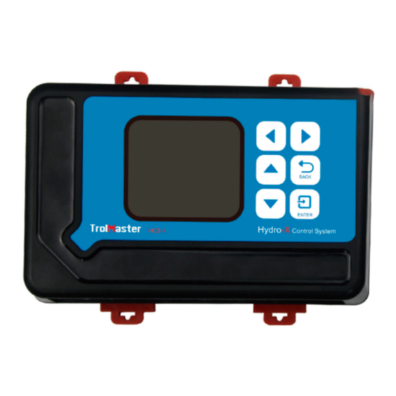
Congratulations on your purchase of the TrolMaster HCS-1 Hydro-X Control
System. This unit is an efficient and affordable way to fully control your grow
rooms. To ensure safety, please read this instruction manual carefully before
installation and follow the instructions herein. It will provide detailed instructions
and guidelines that will help to set up the unit, and to understand the full
capability of this unit. Any use or application of this product, other than for its
original intended purposes are prohibited. Store this manual in a secure place
for future reference.
INTRODUCTION
Hydro-X Control System is the most intelligent and versatile environmental
control system on the market. It could control up to 512 lights, 4 temperature
devices, 2 humidity devices, 2 CO2 devices, 9 preprogram devices. With the
incredible flexibility, anyone could easily customize their own grow room system
for maximum yield.
The system comes with a 3-in-1 sensor detecting temperature, humidity & light.
A CO2 sensor is available for measuring CO2 level. When the measured value
exceeds your custom setting range, a warning message will be sent to your
smartphone. Smoke detectors are also available for smoke detection to alert you
if there is a fire. Hydro-X helps you to monitor your grow environments perfectly.
Hydro-X is specially designed to set up a daily lighting management for your
lighting system. Having 2 separate lines allows the user to create multiple
lighting layouts (and dimming sequence) based on their individual preferences.
This system can efficiently control your lighting system by running a schedule
with advanced functions like auto dimming, overheat shutdown, sunrise &
sunset simulation.
Advertisement
Table of Contents

Related Manuals for TrolMaster HCS-1


Summary of Contents for TrolMaster HCS-1
- Page 1 PLEASE READ FIRST Congratulations on your purchase of the TrolMaster HCS-1 Hydro-X Control System. This unit is an efficient and affordable way to fully control your grow rooms. To ensure safety, please read this instruction manual carefully before installation and follow the instructions herein. It will provide detailed instructions and guidelines that will help to set up the unit, and to understand the full capability of this unit.
- Page 2 Hydro-X can control almost all kinds of devices in your grow rooms by its 4 types of device stations. Temperature device stations, humidity device stations, CO2 device stations and program device stations are designed to be connected to different devices for centralized control. Hydro-X offers a more smart and flexible approach for the connection of the devices you want to be controlled.
- Page 3 RJ12 cables and additional T-shape splitters can be purchased separately. A maximum distance of 1000ft / 300 meters between the HCS-1 Hydro-X Control System and the devices to be controlled. Follow all local and national electrical codes for installation requirements.
-
Page 4: Installation
1. Controller 2. Back Plate(Bracket) 3. 4ft RJ12 Cable 4. T-Shape Splitter 5. 12DC Power Supply 6. 3-in-1 Sensor 7. 16ft RJ12 Cable INSTALLATION... - Page 5 4 tabs back in to lock the unit in place. The interconnecting RJ12 communication cables are available in different lengths, select the correct length for your application. The HCS-1 Hydro-X Control System is supplied with a 4ft and 16ft cable. These interconnecting RJ12 cables are also available in lengths of 25ft and 50ft.
- Page 7 CONNECTIONS CONTINUED... 1. Power Connection: Connect the plug-in power supply to the power (DC) connector. 2. Sensor connection: Connect the RJ12 cable to the SENSORS connector and connect to a splitter on the other end. Plug the 3-in-1 sensor to the splitter for connection. The other connector on the splitter can be used to continuously connect to the next splitter.
- Page 8 this process until all ballasts (fixtures) are connected to the LINE 1. Connect more lights through the LINE 2 port. Same procedures applied for LINE 1. b) For Traditional Lights If connected to traditional lights which are controlled by analog (0-10v) such as Gavita fixtures, a lighting control adapter (signal converter) is necessary to convert the digital signal into analog signal.
- Page 9 INTERNET connector BUTTONS The HCS-1 Hydro-X Control System is extremely easy to use. The backlit 128x128 LCD display will provide the user with the current conditions and access all settings.All settings are accessed by using the 6 pushbuttons on the front of the unit.
-
Page 10: Start Settings
Familiarize yourself with the function of the 6 buttons on the front of the HCS-1 Hydro-X Control System in order to able to access settings, and to better understand how to use the HCS-1 Hydro-X Control System to its greatest potential. - Page 11 HCS-1 Hydro-X Control System, the Welcome screen / page will be displayed. *NOTE : Press ENTER button to rst go to the Conguration page and begin set- Time Setting : please refer to P25 for the time setting so as to change the default time into the current time before use.
- Page 12 1 ). The main menu displays three elements: Temperature Value (��F) eg: 78.8��F Humidity Value (%) eg: 20.2% CO2 Level (PPM) eg: 1200 PPM The top title bar indicates current date & time: Month/Date eg: 09/07 Hour/Minute eg:18:20 Day Mode Night Mode...
- Page 13 Internect Connected No Network Connection (no icon) NOTE : Download the TrolMaster app from App Store or Google Play 2 ). On the Main Menu page, press LEFT button to get access to Devices Status page. The screen will show devices in 3 states .
-
Page 14: Setting Page
3 ). On the Main Menu page, press RIGHT button to get access to Alarm Message page. The LCD screen will show records of all alarm messages. *NOTE : a ). On the Devices Status page, the device states are not suitable to lighting devices.The LCD screen will display the lighting status for two lighting lines L1 &... -
Page 15: Lighting Settings
On the Main Menu page, Device Status page or Alarm Message page, press ENTER button to get access to the SETTING page. The LCD screen will display 6 subjects ( Light / Temp / Humid / CO2 / Program / System) as shown on the picture. - Page 16 On the Setting page, select the Light subject and then press ENTER button to confirm your selection. The screen will display Line 1 and Line 2. Press UP button or DOWN button to select Line 1 or Line 2. Then press ENTER button to get into the configuration page.
- Page 17 2 ) Use the UP and Down button to select the optional item. Press ENTER button, the digits will be flashing, then press UP or DOWN button for change. Finally, press ENTER button to confirm and save change. Wattage : Select the wattage of ballast that will be connected to this line.
-
Page 18: Temperature Settings
Dim at : Select the temperature you want the lights within each line to dim. Stop at : The max temperature that the growing area can get to before shutting down the lights. Normally, set at least 5oF up to 10 degrees F above the "Dim at"... - Page 19 1 ) On the Setting page, select the Temp subject and then press ENTER button to access the Temp setting page. Use the Up button or DOWN button to select the device or Alarm Setting.
- Page 20 2 ) When the Device 1 is selected, user can set the temperatuesetpoint for Day / Night mode for the Device 1. The unit will automatically turn ON the Temp Device 1 when the measured temperature is ABOVE or BELOW the setpoint. Press ENTER button and the Above or Below text will be flashing.
- Page 21 be flashing. Press UP or DOWN button to change the setpoint. Finally, press ENTER button to confirm and save the change. The LCD will display " Setting saved ". 3 ). Press DOWN button to select and enter the Temp Alarm page. The screen will display the Min/Max setpoint.
-
Page 22: Humidity Settings
warning message to your smartphone The setting procedure of other Temp Device Station is same as above HUMIDITY SETTINGS 1 ). On the Setting page, select the Humid subject and then press ENTER button to access the Humid setting page. Use the Up button or Down button to select the Device 1 or Device 2 or Alarm Setting. - Page 23 2 ). When the Device 1 is selected, user can set the humidity setpoint for Day / Night mode for the Device 1. The unit will automatically turn ON the Humid Device 1 when the measured humidity is ABOVE or BELOW the setpoint. Press ENTER button and the Above or Below text will be flashing.
- Page 24 ENTER button to confirm and save the change. The LCD will display " Setting saved". 3 ). Press DOWN button to select and enter the Humid Alarm page. The screen will display the Min/Max setpoint. Press UP or DOWN button to select the Min or Max setpoint.
- Page 25 The setting procedure of other Humid Device Station 2 is same as above CO2 SETTINGS 1 ). On the Setting page, select the CO2 subject and then press ENTER button to access the CO2 setting page. Use the Up button or Down button to select the Device 1 or Device 2 or Alarm setting.
- Page 26 2 ). When the Device 1 is selected, user can set CO2 setpoint during Daytime for the Device 1. The unit will automatically turn ON the CO2 Device 1 when the measured CO2 level is ABOVE or BELOW the setpoint. Press ENTER button and the Above or Below text will be flashing.
- Page 27 press ENTER button to confirm and save the change. User an also turn ON or OFF the Fuzzy Logic mode. Press DOWN button to select the Fuzzy subject and then press UP or DOWN button to change between ON and OFF status. Finally, press ENTER button to confirm and save teh change.
-
Page 28: Program Settings
3 ). Press DOWN button to select and enter the CO2 Alarm page. The screen will display the min/max setpoint. Press UP or DOWN button to select the Min or Max setpoint. The selected item will be highlighted. Then press ENTER button again, the current CO2 setpoint will be flashing. - Page 29 1 ) On the Setting page, select the Program subject and then press ENTER button to confirm your selection. The screen will display total 9 preset numbers: 1, 2, 3...9. You can assign total 9 additional devices with the preset numbers from program device 1 to program device 9.
- Page 30 2). Press number 1 to enter into the Program Device 1 page. There are two timing control type: By Schedule & By Recycle. Press ENTER button, the TICK icon will be highlighted and flashing. Then press UP or DOWN button to select By Schedule or By Recycle.
-
Page 31: System Settings
NOTE : if the total cycle time exceeds 24 hours, the maximum cycle times will be reduced automatically. SYSTEM SETTINGS 1 ).On the Setting page, select the System subject and then press ENTER button to confirm your selection . There are 6 subjects: Temp Format : Select whether to display F or C for temperature measurements. - Page 32 System Reset : Enter the system reset page. Calibration : Enter the temperature humidity and CO2 sensor calibration page. DeadBand : Enter the temperature humidity and CO2 deadband setting page. 2 ). Time Setting : Press UP or DOWN, LEFT or RIGHT buttons to select subject and press ENTER to start setting.
- Page 33 3 ) Override : When Override function is selected on the System page, the cursor will be flashing. Use UP or DOWN, LEFT or RIGHT to move to the device you want to manually override (force) to turn on or off. Press ENTER button to active the override effect.
- Page 34 4 ). CO2 Calibration : After being used for some time, the CO2 sensor may need to be recalibrated if tolerance occurred. Press Enter and UP or DOWN button to adjust the calibration level if you have an accurate reference. Otherwise, the recommended level will be 400. Press Start button to start with the CO2 calibration process.
-
Page 35: General Information
calibration function. 5 ).System Reset : Devices Reset : When using this function, the unit will delete all addresses assigned to the connected Device Stations. User can reconnect Device Stations for resign addresses. Factory Reset : This function will restore the unit to factory default settings. Firmware Update : Update a new firmware to fix bugs or add new functions to the unit. - Page 36 Components that are excluded from warranty are components that have failed due to abnormal usage. In the case of defects of the HCS-1 Hydro-X Control System, the Controller will either be replaced or repaired using new or reconditioned products or parts. If the Controller will be replaced, this limited warranty shall apply to the replacement product for the remaining initial warranty period, i.e.
-
Page 37: Troubleshooting
TROUBLESHOOTING Some of the most common issues or problems can be found within this section. Before returning the unit for service, please consult the troubleshooting points below, additional information can be found online at www.trolmaster.com... - Page 38 Troubleshooting Continued...
-
Page 39: Specifications
WARNING : DO NOT allow the Hydro-X Control System to be exposed to water or excessive heat. DO NOT open or attempt to repair or disassemble the controller, as there are no user-servicealbe parts inside. Opening the controller will void the warranty. If the surface of Hydro-X is dirty, wipe it with a dry towel. - Page 40 ENVIRONMENTAL AND DISPOSAL CONCERNS: THIS PRODUCT CONTAINS A BATTERY AND OTHER COMPONENTS WHICH MUST BE DISPOSED OF PROPERLY. This symbol displayed on a product, its accessories, or its packaging indicates that this product may not be discarded as household waste. Dispose of the equipment through a recycling center that handles electronics and electrical appliances.
Need help?
Do you have a question about the HCS-1 and is the answer not in the manual?
Questions and answers