
Related Manuals for ZOYI ZT-703S

Summary of Contents for ZOYI ZT-703S
- Page 1 User Manual All rights reserved; offenders will be prosecuted. Specifications are subject to change without prior notice.
- Page 2 Limited Warranty and Scope of Rights and Responsibilities This product is eligible for a one-year warranty from the date of purchase. This warranty does not cover blown fuses, damage to general accessories, or damage caused by accidents, negligence, misuse, modifications, pollution, and abnormal operating environments.
-
Page 3: Table Of Contents
Table of Contents Title Page Overview............1 Safety Instructions...........1 Main Interface..........3 Oscilloscope Mode Main Interface......4 Panel Function Keys........7 MENU interface..........8 Oscilloscope Functions Introduction......9 Probe Inspection........9 Safety..........9 Manual Compensation........9 Probe Attenuation Setting......10 Channel Settings........11 Auto Setup..........12 Vertical System........13 Horizontal System........13 Trigger System.........14 Numeric Measurement........15 XY Display Mode........16 Persistence Time........16... - Page 4 Operating Modes........19 Backlight Brightness........19 Baseline Calibration........19 Signal Generator Output Waveform Settings....20 Multimeter Functions Introduction......22 LCD Display Screen........22 Multimeter Input Ports.........24 Measurement Methods........25 Measurement of AC and DC Voltage.......25 Measurement of AC and DC Current.......25 Measuring Resistance........26 Measuring Continuity........26 Measuring Diodes........27 Measuring Capacitance........27 Multimeter Extension Functions.......28 Maintenance and Care.........29...
-
Page 5: Overview
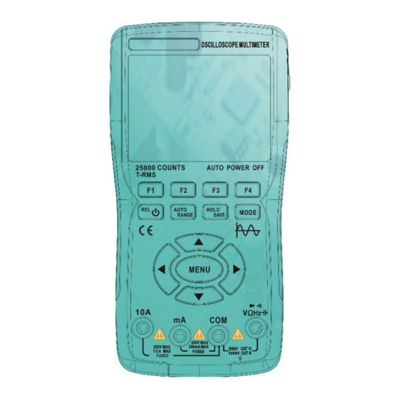
Overview This handheld oscilloscope adopts a dual injection molding process, featuring a beautiful appearance, compact size, convenient portability, and flexible operation. The functional buttons have a clear and intuitive menu interface. The screen utilizes a 3.5-inch IPS full-view color display, with a multimeter display of up to 25,000 counts. - Page 6 • Do not touch unused input ports when the product is connected to the circuit under test. Disconnect the test probes and the circuit before changing the test range. • When the DC voltage under test is higher than 36V, or the AC voltage is higher than 25V, it may cause serious harm to the human body;...
-
Page 7: Main Interface
Main Interface CH1 Input CH2 Input Interface Signal Display Generator Screen Output Port Keys Multimeter Measurement Input Terminal... -
Page 8: Oscilloscope Mode Main Interface
Oscilloscope Mode Main Interface ③ ④ ⑤ ⑥ ① ② ⑦ ⑨ ⑧ ⑩ ⑪ ⑰ ⑯ ⑱ ⑮ ⑬ ⑫ ⑭ RUN: Automatic waveform acquisition state WAIT: Normal trigger mode, blinking waiting Operating for trigger signal Status T.D: Captured triggered waveform data Display STOP: Lock the current waveform, acquisition stopped... - Page 9 Trigger Display the current trigger mode as rising Mode edge or falling edge Level Display the current set trigger voltage value Battery Displaying the current battery status Level and charging status. Horizontal Displaying the current horizontal Trigger time base position triggered. Showing the waveform of CH1 in Channel1 yellow.
- Page 10 Press the up/down keys to adjust the Trigger vertical trigger position and the Cursor left/right keys to adjust the (TRIGGER) horizontal trigger position. Measurement Press this key to select the cursor Cursor axis that needs adjustment. Displaying the coupling mode and CH1 Voltage voltage scale of Channel 1.
-
Page 11: Panel Function Keys
Panel Function Keys F1-F4 Keys: Correspond to the four functional menus displayed on the screen, and you can select the respective function by pressing the keys. Power Button: Long press for 2 seconds to power on/off; in multimeter mode, a short press enters relative value (REL) measurement. -
Page 12: Menu Interface
MENU Interface Main Menu The first page Channel Settings menu The second page Trigger Setup menu The third page Auxiliary Functions menu The fourth page Auxiliary Functions menu The fifth page Extended Functions menu The sixth page ... -
Page 13: Oscilloscope Functions Introduction
Introduction to Oscilloscope Functions Probe Check Safety: When using the probe, to avoid electric shock, ensure that your fingers are kept behind the safety collar on the probe body. Do not touch the metal parts on the top of the probe when it is connected to a high-voltage source. -
Page 14: Probe Attenuation Setting
Introduction to Oscilloscope Functions 3, If it is necessary to cooperate with the adjustment, you can adjust the capacitance on the probe to change the compensation state; the adjustment tool is the accessory adjustment rod that comes with the probe or a suitable non-metallic handle adjustment rod. The adjustment method is as shown in the figure below ... -
Page 15: Channel Settings
Introduction to Oscilloscope Functions Channel Settings Press the MENU key to display the first page of the channel settings menu Press F1 to switch between CH1 and CH2, selecting the channel that needs to be configured. 2. Press F2 to toggle between open and closed. When open, the screen displays the waveform of the current channel, and when closed, the screen does not display the current channel waveform. -
Page 16: Auto Setup
Introduction to Oscilloscope Functions Vertical System The vertical system can be used to set the voltage amplitude, scale size, and position of the waveform. Vertical voltage scale setting: Press the F1 key on the oscilloscope's main interface to select the Voltage/Time menu. Use the panel's upper direction key to increase the voltage setting and the lower direction key to decrease the voltage setting. -
Page 17: Trigger System
Introduction to Oscilloscope Functions 3. Scroll Mode: When the horizontal time base is set to 200ms/div, the oscilloscope automatically enters Scroll Mode. In Scroll Mode, triggering and horizontal position settings are not controlled; the waveform scrolls from left to right. Scroll Mode is suitable for low- speed signals and allows for long-term observation of waveform changes according to measurement needs. - Page 18 Oscilloscope Functions Introduction 1. Auto: Auto triggering continuously refreshes the waveform record inreal- time, without the waveform pausing. 2. Normal: When the amplitude of the captured signal reaches the set trigger level, the trigger system locks and holds the waveform on the screen. The oscilloscope continues continuous acquisition, updating the waveform on the screen with each trigger event, creating continuous triggering.
-
Page 19: Numeric Measurement
Oscilloscope Functions Introduction Numeric Measurement: Press the MENU key and then press the right direction key to enter the sixth- page menu Automatic Measurement: When measuring an unknown signal waveform, press the AUTO key, and the measurement system will automatically recognize and adjust the waveform amplitude and time base. -
Page 20: Xy Display Mode
Oscilloscope Functions Introduction XY Display Mode: Enter the fifth page of the extended function menu and press F1 to select the X-Y display mode. At this point, the screen switches to the vertical display of CH1 and CH2. Based on the frequency ratio and phase difference of the measured signals from CH1 and CH2, it generates various shapes and changes in Lissajous patterns. -
Page 21: Cursor Measurement
Oscilloscope Functions Introduction Cursor Measurement: Typically, during the waveform measurement process, there is a need to capture a specific segment of the waveform to individually measure its amplitude or time. This gives rise to the cursor measurement function. Press the MENU key, then press the right arrow key to enter the... -
Page 22: Waveforms
Oscilloscope Functions Introduction How to Save Measurement Waveforms: To save a measurement waveform, press and hold the [Save] key for 2 seconds. Release the key when the screen displays the 'Save' prompt. The oscilloscope will automatically save the current measured waveform data, sequentially numbered, and store it as images in the memory. -
Page 23: Operating Modes
Oscilloscope Functions Introduction Run Mode: The oscilloscope is equipped with two operating modes: Normal mode and High-Speed mode. Enter the fourth menu, press F3 to toggle between them. Depending on the measurement signal, if the input signal is less than 30MHz, it is recommended to use Normal mode. If the measurement signal frequency is higher than 30MHz, it is advisable to switch to High-Speed mode. -
Page 24: Signal Generator Output Waveform Settings
Signal Generator Functions Introduction Setting the Signal Generator Output Waveform: Navigate to the sixth page menu and press the F4 key for signal output settings. The screen will display the output signal settings window. 1. The signal settings window has four groups of settings. The border color of a setting field turns red to indicate it is currently selected for configuration. - Page 25 Signal Generator Mode Signal Output Enter the sixth page menu, press the F1 key to access the extended applications. At this point, the screen displays options for image browsing and signal output patterns. Choose signal output, then press the MENU key to enter the signal generator output settings interface.
-
Page 26: Multimeter Functions Introduction
Introduction to Multimeter Mode (Enter by pressing the MODE button) ② ① ③ ⑥ ④ ⑤ ⑦ ⑪ ⑧ ⑨ ⑬ ⑭ ⑮ ⑫ ⑩ Pressing the HOLD button on the panel will HOLD ① freeze the current displayed data. Display the current battery level status and Battery ②... - Page 27 Displays the multimeter measurement value, with a Main display ⑥ maximum display of 25,000 counts. Unit symbol Displays the unit symbol of the measured data. ⑦ Automatic Range (AUTO): The multimeter automatically selects the appropriate testing range. Testing Manual Measurement (MANU): Press the RANGE ⑧...
-
Page 28: Multimeter Input Ports
Multimeter Input Terminal Input port for current measurement (≤9.999A) Input port for current measurement (≤250mA) Common (return) port for all measurements Input port for the following measurements: AC/DC voltage Resistance Capacitance VΩHz Frequency Continuity Diode... -
Page 29: Measurement Methods
Measurement Method Measuring AC Voltage and DC Voltage Insert the black probe into the COM terminal and the red probe into the VΩHz terminal. If measuring voltage less than 250mV, press the F4 key once to select the millivolt range or press twice to enter the AC millivolt range. -
Page 30: Measuring Resistance
Disconnect the circuit under test, and connect the meter probes in series with the circuit before restoring power. Read the displayed current value on the screen. • The measured current should not exceed the rated maximum test value to avoid damaging the instrument and jeopardizing personal safety. If the magnitude of the current to be measured is unknown, perform a preliminary test on the A-terminal, then select the test port and range based on the displayed value. -
Page 31: Measuring Diodes
Measuring Diode 1.In the continuity mode, press F2 to enter the diode test mode. 2.Connect the red test lead to the positive lead of the diode under test and the black test lead to the negative lead. Then, read the forward voltage displayed on the screen. -
Page 32: Multimeter Extension Functions
Multimeter Extended Functions When in multimeter mode, press the MENU key, and the screen will display the following extended menu: F1: Switch language between Chinese and English. F2: Set the auto-off time to 1 minute, 10 minutes, 30 minutes, 60 minutes, 120 minutes, or turn off (no auto-off time limit). -
Page 33: Maintenance And Care
Maintenance and Care Except for battery and fuse replacement, do not attempt to repair this product or alter its circuit unless you have the necessary qualifications and possess corresponding calibration, performance testing, and maintenance operation instructions. Cleaning the Product Use a damp cloth and mild detergent to clean the casing. Do not use corrosive or solvent-based cleaners. -
Page 34: Battery Storage
Battery Storage If the instrument is not used for an extended period (such as more than 6 months), it should be charged to 50%-70% and stored in a cool, dry environment. If the lithium battery shows signs of rust, leakage, swelling, etc., it should be immediately removed and disposed of. -
Page 35: Technical Specifications
Technical Specifications General Technical Specifications for Multimeter Display (IPS) 25000 counts Range Automatic/Manual Material ABS+TPE Sampling Rate 3 times per second True RMS √ Data Hold √ Screen Backlight √ Low Battery Indicator √ Auto Power Off √ Mechanical Technical Specifications Dimensions 177*89*40mm Weight... -
Page 36: Multimeter Specifications
Multimeter Technical Specifications Function Range Resolution Accuracy 2.5000V 0.0001V 25.000V 0.001V DC Voltage (V) 250.00V 0.01V ±(0.05% 1000.0V 0.1V 25.000mV 0.001mV DC Voltage (mV) 250.00mV 0.01mV 2.5000V 0.0001V 25.000V 0.001V AC Voltage (V) 250.00V 0.01V ±(0.5%+3) 750.0V 0.1V 25.000mV 0.001mV AC Voltage (mV)... - Page 37 Function Range Resolution Accuracy 2.5000A 0.0001A DC Current ±(0.5%+3) (A) 10.000A 0.001A 25.000mA 0.001mA DC Current ±(0.5%+3) (mA) 250.00mA 0.01mA 2.5000A 0.0001A AC Current ±(0.8%+3) (A) 10.000A 0.001A 25.000mA 0.001mA AC Current ±(0.8%+3) (μA/mA) 250.00mA 0.01mA AC Current Frequency Response:40Hz~1kHz 250.00Ω...
- Page 38 Function Range Resolution Accuracy 9.999nF 0.001nF ±(5.0%+20) 99.99nF 0.01nF 999.9nF 0.1nF 9.999μF 0.001μF ±(2.0%+5) Capacitance 99.99μF 0.01μF 999.9μF 0.1μF 9.999mF 0.001mF ±(5.0%+5) 99.99mF 0.01mF 99.99Hz 0.01Hz Frequency (Up to 999.9Hz 0.1Hz 100kHz only 9.999kHz 0.001kHz ±(0.1%+2) applicable in AC 99.99kHz 0.01kHz Voltage 999.9kHz...
-
Page 39: Oscilloscope Specifications
Oscilloscope Specifications Characteristics Description Bandwidth 50MHZ Dual Channel Sampling Method Real-time sampling Sampling Sampling Rate 200M/280MSa/s Channels Dual Channel Input Coupling DC, AC Input Impedance 1MΩ,@16pf Input Attenuation X1, X10 Maximum Input X1 range <150V, X10 range <300V Voltage (DC+AC peak) Rate Range 1.5Sa/s - 280MSa/s Interpolation...
Need help?
Do you have a question about the ZT-703S and is the answer not in the manual?
Questions and answers