Table of Contents
Advertisement
Advertisement
Table of Contents

Related Manuals for Asus PRIME X570-PRO


Summary of Contents for Asus PRIME X570-PRO
- Page 1 PRIME X570-PRO...
- Page 2 Product warranty or service will not be extended if: (1) the product is repaired, modified or altered, unless such repair, modification of alteration is authorized in writing by ASUS; or (2) the serial number of the product is defaced or missing.
-
Page 3: Table Of Contents
Contents Safety information ....................... v About this guide ......................vi PRIME X570-PRO specifications summary ............viii Package contents ...................... xii Installation tools and components ................. xiii Chapter 1: Product Introduction Motherboard overview ................1-1 1.1.1 Before you proceed ..............1-1 1.1.2... - Page 4 3.8.2 CSM (Compatibility Support Module) ........3-18 3.8.3 Secure Boot ................3-18 Tool menu ....................3-18 3.9.1 ASUS EZ Flash 3 Utility ............3-18 3.9.2 ASUS User Profile..............3-18 3.9.3 ASUS SPD Information ............. 3-19 3.9.4 Graphics Card Information ............3-19 3.9.5...
-
Page 5: Safety Information
Safety information Electrical safety • To prevent electrical shock hazards, disconnect the power cable from the electrical outlet before relocating the system. • When adding or removing devices to or from the system, ensure that the power cables for the devices are unplugged before the signal cables are connected. If possible, disconnect all power cables from the existing system before you add a device. -
Page 6: About This Guide
Refer to the following sources for additional information and for product and software updates. ASUS website The ASUS website (www.asus.com) provides updated information on ASUS hardware and software products. Optional documentation Your product package may include optional documentation, such as warranty flyers, that may have been added by your dealer. - Page 7 Conventions used in this guide To ensure that you perform certain tasks properly, take note of the following symbols used throughout this manual. DANGER/WARNING: Information to prevent injury to yourself when trying to complete a task. CAUTION: Information to prevent damage to the components when trying to complete a task.
-
Page 8: Prime X570-Pro Specifications Summary
.C.)/2933/2800/2666/2400/2133 MHz, un-buffered memory Dual channel memory architecture ECC Memory (ECC mode) support varies by CPU. * Refer to www.asus.com for the Memory QVL (Qualified Vendors List). ** The maximum memory capacity supported vary depending on the CPU you installed. - Page 9 PRIME X570-PRO specifications summary and 2 Gen AMD Ryzen™ Processors - Supports NVIDIA 2-Way SLI Technology ® ® - Supports AMD 3-Way CrossFireX™ Technology Multi-GPU support and 1 Gen AMD Ryzen™ with Radeon™ Vega Graphics Processors - Supports AMD 2-Way CrossFireX™ Technology Gen AMD Ryzen™...
- Page 10 - Aura RGB Strip Headers ASUS Q-Design - ASUS Q-Slot - ASUS Q-DIMM - ASUS Q-Connector - ASUS Q-LED (CPU, DRAM, VGA, Boot Device LED) ASUS Exclusive Features - OptiMem - Turbo LAN - ASUS Ai Charger - ASUS AI Suite 3...
- Page 11 - ASUS Overvoltage Protection - World-class circuit-protecting Special Features power design - ASUS DIGI+ VRM - Digital power design with Dr. MOS - ASUS DRAM Overcurrent Protection: Enhanced DRAM overcurrent protection - ASUS Stainless-Steel Back I/O: 3X corrosion-resistance for...
-
Page 12: Package Contents
1 x Power-on button 1 x T_Sensor Header 256 Mb Flash ROM, UEFI AMI BIOS, PnP, SM BIOS 3.2, ACPI 6.2, Multi-language BIOS, ASUS EZ Flash 3, CrashFree BIOS 3, F6 Qfan Control, F3 My Favorites, Last Modified log, F12 BIOS... -
Page 13: Installation Tools And Components
Installation tools and components 1 Bag of screws Phillips (cross) screwdriver PC chassis Power supply unit AMD AM4 CPU AMD AM4/AM3 compatible CPU Fan DDR4 DIMM SATA hard disk drive SATA optical disc drive (optional) Graphics card (optional) The tools and components in the table above are not included in the motherboard package. xiii... -
Page 15: Chapter 1: Product Introduction
Before you install or remove any component, ensure that the ATX power supply is switched off or the power cord is detached from the power supply. Failure to do so may cause severe damage to the motherboard, peripherals, or components. ASUS PRIME X570-PRO... -
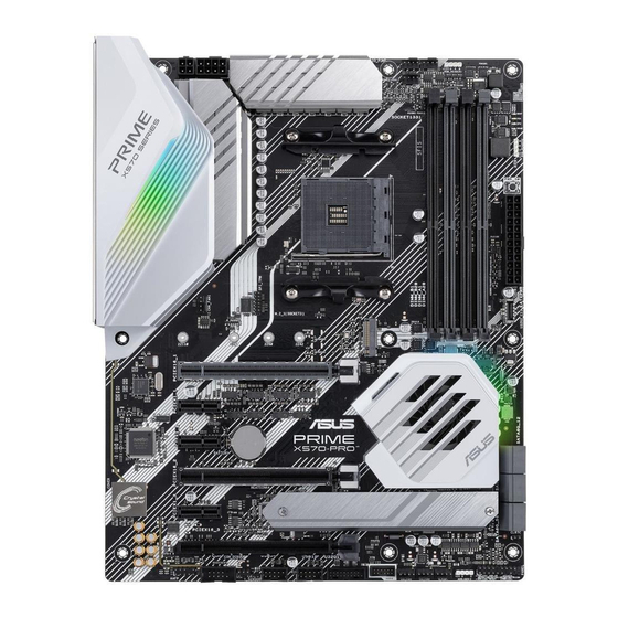
Page 16: Motherboard Layout
1.1.2 Motherboard layout 24.4cm(9.6in) CPU_FAN AIO_PUMP RGB_HEADER1 KBMS EATX12V_1 _U32G1 PLUG_8PIN_PWR1 _910 CPU_OPT EATX12V_2 BOOT_DEVICE_LED VGA_LED DIGI CPU_LED DRAM_LED +VRM HDMI_DP U32G2_C8 PWR_SW U32G2_7 U32G2_56 LAN_U32G1_34 SPI_TPM AUDIO 256Mb BIOS 22110 2280 2260 2242 PCIEX16_1 Intel ® PCIEX1_1 I211AT ® Super PCIEX1_2 X570... - Page 17 19. Thermal sensor connector (2-pin T_SENSOR) 1-15 20. Serial port connector (10-1 pin COM) 1-19 21. Front panel audio connector (10-1 pin AAFP) 1-12 22. SPI_TPM connector (14-1 pin SPI_TPM) 1-12 23. 8-pin power plug LED 1-22 ASUS PRIME X570-PRO...
-
Page 18: Central Processing Unit (Cpu)
The motherboard comes with four Double Data Rate 4 (DDR4) Dual Inline Memory Modules (DIMM) slots. A DDR4 module is notched differently from a DDR, DDR2, or DDR3 module. DO NOT install a DDR, DDR2, or DDR3 memory module to the DDR4 slot. PRIME X570-PRO 288-pin DDR4 DIMM sockets Chapter 1: Product Introduction... - Page 19 (D/C) from the same vendor. Check with the vendor to get the correct memory modules. • Visit the ASUS website for the latest QVL.same vendor. Check with the vendor to get the correct memory modules. ASUS PRIME X570-PRO...
-
Page 20: Expansion Slots
1.1.5 Expansion slots Unplug the power cord before adding or removing expansion cards. Failure to do so may cause you physical injury and damage motherboard components. PCIEX16_1 PCIEX1_1 PCIEX1_2 PCIEX16_2 PCIEX1_3 PCIEX16_3 Slot No. Slot Description PCIe 4.0 / 3.0 x16_1 slot PCIe 4.0 x1_1 slot PCIe 4.0 x1_2 slot PCIe 4.0 / 3.0 x16_2 slot... - Page 21 Single VGA/PCIe card • We recommend that you provide sufficient power when running CrossFireX or SLI ® mode. • Connect chassis fans to the motherboard chassis fan connectors when using multiple graphics cards for better thermal environment. ASUS PRIME X570-PRO...
-
Page 22: Onboard Leds
VGA (WHITE) CPU (RED) DRAM (YELLOW) PRIME X570-PRO CPU/DRAM/BOOT_DEVICE/VGA LED The Q LEDs provide the most probable cause of an error code as a starting point for troubleshooting. The actual cause may vary from case to case. Chapter 1: Product Introduction... -
Page 23: Headers
CLRTC PIN 1 PRIME X570-PRO Clear RTC RAM To erase the RTC RAM: Turn OFF the computer and unplug the power cord. Use a metal object such as a screwdriver to short the two pins. - Page 24 RGB_HEADER2 +12V PIN 1 PRIME X570-PRO RGB_HEADER connectors The RGB header supports 5050 RGB multi-color LED strips (12V/G/R/B), with a maximum power rating of 3A (12V), and no longer than 3 m. Before you install or remove any component, ensure that the ATX power supply is switched off or the power cord is detached from the power supply.
- Page 25 LED strips. ADD_GEN2 PIN 1 PRIME X570-PRO ADD_GEN2 header The addressable gen 2 RGB header supports WS2812B addressable RGB LED strips (5V/ Data/Ground), with a maximum power rating of 3A (5V) and a maximum of 120 LEDs Before you install or remove any component, ensure that the ATX power supply is switched off or the power cord is detached from the power supply.
-
Page 26: Internal Connectors
Audio. Connect one end of the front panel audio I/O module cable to this connector. AAFP HD-audio-compliant pin definition PRIME X570-PRO front panel audio connector We recommend that you connect a high-definition front panel audio module to this connector to avail of the motherboard’s high-definition audio capability. SPI_TPM connector (14-1 pin SPI_TPM) - Page 27 RSATA_RXN2 RSATA_RXP1 RSATA_RXP2 PRIME X570-PRO SATA 6 Gb/s connectors • These connectors are set to [AHCI] by default. If you intend to create a Serial ATA RAID set using these connectors, set the SATA Mode Selection item in the BIOS to [RAID].
- Page 28 TX1- TX1+ VBUS PRIME X570-PRO USB3.2 Gen2 front panel connector USB 3.2 Gen 1 (up to 5Gbps) connector (20-1 pin U32G1_12) This connector allows you to connect a USB 3.2 Gen 1 module for additional USB 3.2 Gen 1 front or rear panel ports. With an installed USB 3.2 Gen 1 module, you can enjoy all the benefits of USB 3.2 Gen 1 including faster data transfer speeds of up to...
- Page 29 USB34 USB12 PIN 1 PIN 1 PRIME X570-PRO USB2.0 connectors Never connect a 1394 cable to the USB connectors. Doing so will damage the motherboard! Thermal sensor connector (2-pin T_SENSOR) This connector is for the thermistor cable that allows you to monitor the temperature of your motherboard’s critical components and connected devices.
- Page 30 PIN 1 HDD_LED RESET PLED PRIME X570-PRO System panel connector • System power LED (2-pin or 3-1 pin PLED) The 2-pin or 3-1 pin connector is for the system power LED. Connect the chassis power LED cable to this connector. The system power LED lights up when you turn on the system power, and blinks when the system is in sleep mode.
- Page 31 CHA FAN PWM CHA FAN IN CHA FAN PWR W_PUMP+ PRIME X570-PRO Fan connectors • DO NOT forget to connect the fan cables to the fan connectors. Insufficient air flow inside the system may damage the motherboard components. These are not jumpers! Do not place jumper caps on the fan connectors! •...
- Page 32 +3 Volts -12 Volts +3 Volts +3 Volts PIN 1 PRIME X570-PRO ATX power connectors • DO NOT connect the 4-pin power plug only, the motherboard may overheat under heavy usage. • Ensure to connect the 8-pin power plug, or both the 8-pin and 4-pin power plugs.
- Page 33 This connector is for a serial (COM) port. Connect the serial port module cable to this connector, then install the module to a slot opening at the back of the system chassis. PIN 1 PRIME X570-PRO Serial port (COM) connector The COM module is purchased separately. LED connector (13-pin LED1_CON) The LED connector is for connecting an RGB Card under the rear I/O cover.
- Page 34 This connector allows you to connect a compatible PSU. NODE PIN 1 PRIME X570-PRO Node connector Visit https://www.asus.com for more information about the devices and latest compatibility list. Power-on button (PWR_SW) The motherboard comes with a power-on button that allows you to power up or wake up the system.
- Page 35 22110 2280 2260 2242 PRIME X570-PRO M.2 sockets • For 3 Gen AMD Ryzen™ Processors, the M.2_1 socket supports PCIe 4.0 x4 mode and SATA mode M Key design and type 2242 / 2260 / 2280 / 22110 storage devices.
- Page 36 8-pin Plug Power LED The 8-pin Power Plug LED lights up to indicate that the 8-pin power plug is not connected. PLUG_8PIN_LED PRIME X570-PRO PLUG_8PIN_LED • DO NOT connect the 4-pin power plug only, the motherboard may overheat under heavy usage.
-
Page 37: Chapter 2: Basic Installation
The AMD AM4 socket is compatible with AMD AM4 processors. Ensure you use a CPU designed for the AM4 socket. The CPU fits in only one correct orientation. DO NOT force the CPU into the socket to prevent bending the connectors on the socket and damaging the CPU! ASUS PRIME X570-PRO... -
Page 38: Cooling System Installation
2.1.2 Cooling system installation Apply the Thermal Interface Material to the CPU cooling system and CPU before you install the cooling system, if necessary. CPU heatsink and fan assembly Type 1 Chapter 2: Basic Installation... - Page 39 CPU heatsink and fan assembly Type 2 When using this type of CPU fan, remove the screws and the retention module only. Do not remove the plate on the bottom. ASUS PRIME X570-PRO...
- Page 40 To install an AIO cooler AIO_PUMP CPU_FAN CPU_OPT Chapter 2: Basic Installation...
-
Page 41: Motherboard Installation
Place the motherboard into the chassis, ensuring that its rear I/O ports are aligned to the chassis’ rear I/O panel. Place nine (9) screws into the holes indicated by circles to secure the motherboard to the chassis. DO NOT over tighten the screws! Doing so can damage the motherboard. ASUS PRIME X570-PRO... -
Page 42: Dimm Installation
2.1.4 DIMM installation To remove a DIMM Chapter 2: Basic Installation... -
Page 43: Atx Power Connection
2.1.5 ATX power connection • DO NOT connect the 4-pin power plug only, the motherboard may overheat under heavy usage. • Ensure to connect the 8-pin power plug, or both the 8-pin and 4-pin power plugs. ASUS PRIME X570-PRO... -
Page 44: Sata Device Connection
2.1.6 SATA device connection Chapter 2: Basic Installation... -
Page 45: Front I/O Connector
This connector will only fit in one orientation. Push the connector until it clicks into place. To install USB 3.2 Gen 1 connector To install USB 2.0 connector USB 3.2 Gen 1 USB 2.0 To install front panel audio connector AAFP ASUS PRIME X570-PRO... -
Page 46: Expansion Card Installation
2.1.8 Expansion card installation To install PCIe x16 cards To install PCIe x1 cards Chapter 2: Basic Installation 2-10... -
Page 47: M.2 Installation
2.1.9 M.2 installation Supported M.2 type varies per motherboard. M.2_1 installation ASUS PRIME X570-PRO 2-11... - Page 48 M.2_2 installation Chapter 2: Basic Installation 2-12...
-
Page 49: Motherboard Rear And Audio Connections
3.2 Gen 1 / Gen 2 ports are controlled by the xHCI controller. • We strongly recommend that you connect USB 3.2 Gen 2 devices to USB 3.2 Gen 2 ports for faster and better performance from your USB 3.2 Gen 2 devices. ASUS PRIME X570-PRO 2-13... - Page 50 * LAN ports LED indications ACT/LINK SPEED Activity Link LED Speed LED Status Description Status Description No link 10 Mbps connection Orange Linked Orange 100 Mbps connection LAN port Orange (Blinking) Data activity Green 1 Gbps connection Orange (Blinking Ready to wake up then steady) from S5 mode ** Audio 2, 4, 6 or 8-channel configuration...
-
Page 51: Audio I/O Connections
2.2.2 Audio I/O connections Audio I/O ports Connect to Headphone and Mic Connect to Stereo Speakers Connect to 2-channel Speakers ASUS PRIME X570-PRO 2-15... - Page 52 Connect to 4-channel Speakers Connect to 6-channel Speakers Connect to 8-channel Speakers Chapter 2: Basic Installation 2-16...
-
Page 53: Starting Up For The First Time
While the system is ON, press the power button for less than four seconds to put the system on sleep mode or soft-off mode, depending on the BIOS setting. Press the power button for more than four seconds to let the system enter the soft-off mode regardless of the BIOS setting. ASUS PRIME X570-PRO 2-17... -
Page 54: Chapter 3: Bios Setup
BIOS Setup Knowing BIOS The new ASUS UEFI BIOS is a Unified Extensible Interface that complies with UEFI architecture, offering a user-friendly interface that goes beyond the traditional keyboard- only BIOS controls to enable a more flexible and convenient mouse input. You can easily navigate the new UEFI BIOS with the same smoothness as your operating system. -
Page 55: Bios Setup Program
RTC RAM via the Clear CMOS button. • The BIOS setup program does not support the Bluetooth devices. Please visit ASUS website for the detailed BIOS content manual. BIOS menu screen The BIOS Setup program can be used under two modes: EZ Mode and Advanced Mode. -
Page 56: Ez Mode
Click to go to Advanced mode Loads optimized Search on the FAQ default settings Click to display boot devices Selects the boot device priority The boot device options vary depending on the devices you installed to the system. ASUS PRIME X570-PRO... -
Page 57: Advanced Mode
3.2.2 Advanced Mode The Advanced Mode provides advanced options for experienced end-users to configure the BIOS settings. The figure below shows an example of the Advanced Mode. Refer to the following sections for the detailed configurations. To switch from EZ Mode to Advanced Mode, click Advanced Mode(F7) or press the <F7> hotkey. - Page 58 Refer to section 3.2.3 QFan Control for more information. Search (F9) This button allows you to search by BIOS item name, enter the item name to find the related item listing. ASUS PRIME X570-PRO...
- Page 59 Move your mouse over this button to show a QR code, scan this QR code on your mobile device to connect to the BIOS FAQ web page of the ASUS support website. You can also scan the following QR code:...
-
Page 60: Q-Fan Control
Click to activate DC Mode configured PWM Mode Select a profile to Click to apply the fan setting apply to your fans Click to undo the Click to go back to main menu changes Select to manually configure your fans ASUS PRIME X570-PRO... - Page 61 Configuring fans manually Select Manual from the list of profiles to manually configure your fans’ operating speed. Speed points Select to manually configure your fans To configure your fans: Select the fan that you want to configure and to view its current status. Click and drag the speed points to adjust the fans’...
-
Page 62: Ez Tuning Wizard
To start OC Tuning: Press <F11> on your keyboard or click from the BIOS screen to open EZ Tuning Wizard screen, and then click Next. Select a PC scenario Daily Computing or Gaming/Media Editing, and then click Next. ASUS PRIME X570-PRO... -
Page 63: My Favorites
Select a Main Cooling System BOX cooler, Tower cooler, Water cooler, or I’m not sure, then click Next. After selecting the Main Cooling System, click Next then click Yes to start the OC Tuning. My Favorites My Favorites is your personal space where you can easily save and access your favorite BIOS items. -
Page 64: Main Menu
RTC RAM via the Clear CMOS button. The Administrator or User Password items on top of the screen show the default [Not • Installed]. After you set a password, these items show [Installed]. 3-11 ASUS PRIME X570-PRO... -
Page 65: Ai Tweaker Menu
EPU Power Saving Mode The ASUS EPU (Energy Processing Unit) sets the CPU in its minimum power consumption settings. Enable this item to set lower CPU core/cache voltage and achieve the best energy saving condition. Configuration options: [Disabled] [Enabled] The items in this menu may vary based on the CPU installed. -
Page 66: Advanced Menu
This item allows you enable or disable simultaneous multithreading. Configuration options: [Disabled] [Auto] Core Leveling Mode This item allows you to change the number of compute unit in the system. Configuration options: [Automatic mode] [One Computer Unit] 3-13 ASUS PRIME X570-PRO... -
Page 67: Nb Configuration
3.6.3 NB Configuration NB Configuration function varies based on the CPU installed. Primary Video Device Selects the primary display device. Configuration options: [IGFX Video] [PCIE Video] 3.6.4 SATA Configuration While entering Setup, the BIOS automatically detects the presence of SATA devices. The SATA Port items show Empty if no SATA device is installed to the corresponding SATA port. -
Page 68: Onboard Devices Configuration
Enables or disables the Intel PXE OPROM. Configuration options: [On] [Off] USB power delivery in Soft Off state S5 This item allows you to charge USB devices even when the system is in Soft Off state S5. Configuration options: [Disabled] [Enabled] 3-15 ASUS PRIME X570-PRO... -
Page 69: Apm Configuration
3.6.6 APM Configuration The items in this menu allow you to set system wake and sleep settings. ErP Ready [Disabled] This item allows you to switch off some power at S4+S5 or S5 to get the system ready for ErP requirement. When set to [Enabled], all other PME options are switched off. Configuration options: [Disabled] [Enable(S4+S5)] [Enable(S5)] Restore On AC Power Loss This item allows your system to go to ON state, OFF state, or both states after an AC power... -
Page 70: Hdd/Ssd Smart Information
Accelerates the boot speed on the next boot after an AC power loss. Setup Mode [Advanced Mode] This item allows you to go to Advanced Mode of the BIOS after POST. [EZ Mode] This item allows you to go to EZ Mode of the BIOS after POST. 3-17 ASUS PRIME X570-PRO... -
Page 71: Csm (Compatibility Support Module)
3.9.1 ASUS EZ Flash 3 Utility This item allows you to run ASUS EZ Flash 3. When you press <Enter>, a confirmation message appears. Use the left/right arrow key to select between [Yes] or [No], then press <Enter> to confirm your choice. -
Page 72: Asus Spd Information
This feature is only supported on selected ASUS graphics cards. 3.9.5 ASUS Armoury Crate This item allows you to download and install the ASUS ARMOURY CRATE app. 3.10 Exit menu The Exit menu items allow you to load the optimal default values for the BIOS items, and save or discard your changes to the BIOS items. -
Page 73: Updating Bios
® ASUS EZ Flash 3: Updates the BIOS using a USB flash drive. ASUS CrashFree BIOS 3: Restores the BIOS using the motherboard support DVD or a USB flash drive when the BIOS file fails or gets corrupted. 3.11.1... -
Page 74: Asus Ez Flash 3
3.11.2 ASUS EZ Flash 3 ASUS EZ Flash 3 allows you to download and update to the latest BIOS through the Internet without having to use a bootable floppy disk or an OS-based utility. Updating through the Internet varies per region and Internet conditions. Check your local Internet connection before updating through the Internet. - Page 75 To update the BIOS by Internet: Enter the Advanced Mode of the BIOS setup program. Go to the Tool menu to select ASUS EZ Flash Utility and press <Enter>. Select via Internet. Press the Left/Right arrow keys to select an Internet connection method, and then press <Enter>.
-
Page 76: Asus Crashfree Bios 3
The BIOS file in the motherboard support DVD may be older than the BIOS file published on the ASUS official website. If you want to use the newer BIOS file, download the file at https://www.asus.com/support/ and save it to a USB flash drive. - Page 77 Chapter 3: BIOS Setup 3-24...
-
Page 78: Appendix
Appendix Notices FCC Compliance Information Responsible Party: Asus Computer International Address: 48720 Kato Rd., Fremont, CA 94538, USA Phone / Fax No: (510)739-3777 / (510)608-4555 This device complies with part 15 of the FCC Rules. Operation is subject to the following two conditions: (1) This device may not cause harmful interference, and (2) this device must accept any interference received, including interference that may cause undesired operation. - Page 79 Compliance Statement of Innovation, Science and Economic Development Canada (ISED) This device complies with Innovation, Science and Economic Development Canada licence exempt RSS standard(s). Operation is subject to the following two conditions: (1) this device may not cause interference, and (2) this device must accept any interference, including interference that may cause undesired operation of the device.
- Page 80 ASUS Recycling/Takeback Services ASUS recycling and takeback programs come from our commitment to the highest standards for protecting our environment. We believe in providing solutions for you to be able to responsibly recycle our products, batteries, other components as well as the packaging materials.
- Page 81 доступний на: www.asus.com/support Cijeli tekst EU izjave o sukladnosti dostupan je na: www.asus.com/support Türkçe AsusTek Computer Inc., bu aygıtın temel gereksinimlerle ve ilişkili Čeština Společnost ASUSTeK Computer Inc. tímto prohlašuje, že toto Yönergelerin diğer ilgili koşullarıyla uyumlu olduğunu beyan eder.
-
Page 82: Asus Contact Information
+1-510-739-3777 +1-510-608-4555 Web site http://www.asus.com/us/ Technical Support Support fax +1-812-284-0883 Telephone +1-812-282-2787 Online support http://qr.asus.com/techserv ASUS COMPUTER GmbH (Germany and Austria) Address Harkort Str. 21-23, 40880 Ratingen, Germany +49-2102-959931 Web site http://www.asus.com/de Online contact http://eu-rma.asus.com/sales Technical Support Telephone +49-2102-5789555 Support Fax... - Page 83 Appendix...
Need help?
Do you have a question about the PRIME X570-PRO and is the answer not in the manual?
Questions and answers