Table of Contents
Advertisement
Quick Links
May, 2007
Table of Contents
Cautionary Notes ..............................................................2
Main Specifications ...........................................................3
Location of Controls .........................................................4
Location of Controls Parts List........................................5
Exploded View (1).............................................................6
Exploded View (1) Parts List ...........................................7
Exploded View (2).............................................................8
Exploded View (2) Parts List ...........................................9
Exploded View (3)...........................................................10
Exploded View (3) Parts List .........................................11
Copyright © 2007 ROLAND CORPORATION
All rights reserved. No part of this publication may be reproduced in any form without the written permission
of ROLAND CORPORATION.
Revice Infomation
July, 18, 2008
Part Name Corrected
17058511E0
SERVICE NOTES
Issued by RJA
Parts List ...........................................................................12
Verifying the Version Number......................................16
Factory Reset ....................................................................16
System Update.................................................................16
Test Mode .........................................................................16
Circuit Board (Jack Board) .............................................24
Circuit Diagram (Jack Board) ........................................26
Circuit Board (Panel Board)...........................................28
Circuit Diagram (Panel Board)......................................30
(p. 7, p. 13)
Printed in Japan (0370) (SC-MZ)
RE-20
Advertisement
Table of Contents

Related Manuals for Boss RE-20 COSM


Summary of Contents for Boss RE-20 COSM
-
Page 1: Table Of Contents
May, 2007 RE-20 SERVICE NOTES Issued by RJA Table of Contents Cautionary Notes ..............2 Parts List ................12 Main Specifications ............3 Verifying the Version Number........16 Location of Controls ............4 Factory Reset ..............16 Location of Controls Parts List........5 System Update..............16 Exploded View (1).............6 Test Mode .................16 Exploded View (1) Parts List ...........7 Circuit Board (Jack Board) ..........24... -
Page 2: Cautionary Notes
May, 2007 RE-20 Cautionary Notes Before beginning the procedure, please read through this document. The matters described may differ according to the model. No User Data This product cannot save user data. Backing up user data during servicing is not required. Parts List A component whose part code is ******** cannot be supplied as a service part because one of the following reasons applies. -
Page 3: Main Specifications
May, 2007 RE-20 ●Dimensions Main Specifications 173 (W) x 158 (D) x 57 (H) mm RE-20 (40370): Space Echo 6-13/16 (W) x 6-1/4 (D) x 2-1/4 (H) inches ●Weight ●Controls • EFFECT ON/OFF pedal 1.2 kg / 2 lbs 11 oz (including batteries) •... -
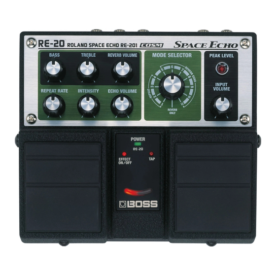
Page 4: Location Of Controls
May, 2007 RE-20 Location of Controls fig.panel.eps... -
Page 5: Location Of Controls Parts List
May, 2007 RE-20 Location of Controls Parts List Part Code Part Name Description Q’ty G2357116R0 PEDAL PLATE 62X53 G2217784R0 LED PANEL G2147896R0 LED COVER G2217785R0 PANEL 75D522N0R0 MINIMUM VR KNOB G2477521R0 R-KNOB G2207420R0 LED ESCUTION G2127314R0 REAR PANEL F3449415R0 ADAPTOR JACK KM02009BB F3159104R0 SLIDE SWITCH... -
Page 6: Exploded View (1)
May, 2007 RE-20 Exploded View (1) fig.bunkai1.eps... -
Page 7: Exploded View (1) Parts List
May, 2007 RE-20 Exploded View (1) Parts List Part Code Part Name Description Q’ty 75E282C0R0 CASE G2357111R0 CUSHION R H5029851R0 PEDAL SHAFT 22157702R0 PEDAL GUIDE BUSH 22177109R0 COIL SPRING G2357116R0 PEDAL PLATE 62X53 G2357115R0 PEDAL FOOT 75E282R0R0 PEDAL R 75E282L0R0 PEDAL L H5029852R0 SCREW 4M3 FEBZC... -
Page 8: Exploded View (2)
May, 2007 RE-20 Exploded View (2) fig.bunkai2.eps... -
Page 9: Exploded View (2) Parts List
May, 2007 RE-20 Exploded View (2) Parts List Part Code Part Name Description Q’ty 75D522N0R0 MINIMUM VR KNOB G2477521R0 R-KNOB G2207420R0 LED ESCUTION G2217785R0 PANEL G2217784R0 LED PANEL G2147807R0 JACK HOLDER 75E283S0R0 PANEL+JACK BOARD ASSY NOTE: ‘PANEL+JACK BOARD ASSY’ includes the following parts. ******** JACK BOARD ASSY ********... -
Page 10: Exploded View (3)
May, 2007 RE-20 Exploded View (3) fig.bunkai3.eps... -
Page 11: Exploded View (3) Parts List
May, 2007 RE-20 Exploded View (3) Parts List Part Code Part Name Description Q’ty 75D422E0R0 BOTTOM COVER G2357118R0 BOTTOM FOOT G2017621R0 BATTERY COVER G2017620R0 BATTERY CASE G2177308R0 BATTERY TERMINAL (+) G2177309R1 BATTERY TERMINAL (-) G2177307R1 BATTERY TERMINAL (+-) G2257130R0 BATTERY INSULATING SHEET G2547131R0 BOTTOM COVER LABEL H5019115R0... -
Page 12: Parts List
May, 2007 RE-20 Parts List Due to one or more of the following reasons, SAFETY PRECAUTIONS: parts with parts code ******** cannot be supplied as service parts. The parts marked have safety-related characteristics. Use only listed parts for replacement. • Part supplied only as a component in a complete assembly •... - Page 13 May, 2007 RE-20 POTENTIOMETER F3229194R0 POTENTIOMETER RV112FF-40B1-125F-0B20K- VR3 on Panel 1H57 F3229167R1 POTENTIOMETER RD902F-40-125F-A250K-00DL5 VR2 on Panel F3279802R0 9M/M POTENTIOMETER RD901F-40-125F-B54-00D VR4,VR5,VR6,VR9 on Panel F3279819R0 POTENTIOMETER RD901-40-125F-B54-0CD VR7,VR8 on Panel CAPACITOR F5369547R0 CAPACITOR RV2-25V470MU-R 47/25 C193,C195,C197 on Panel 02345101 CAPACITOR RV2-16V100MU-R 10/16 C199,C201,C202,C203,C209 on Panel INDUCTOR, COIL, FILTER...
- Page 14 May, 2007 RE-20 ACCESSORIES (Standard) G6017303R3 LEAFLET JAPANESE/ENGLISH G6017467R0 OWNER’S MANUAL JAPANESE G6027121R1 OWNER’S MANUAL ENGLISH...
- Page 15 May, 2007 RE-20...
-
Page 16: Verifying The Version Number
May, 2007 RE-20 Verifying the Version Test Mode Number Items Required Connect an AC adapter (PSA series). • Noise meter Adjust the MODE SELECTOR control to REVERB ONLY, and turn all • Oscilloscope other controls all the way counterclockwise (minimum). •... - Page 17 May, 2007 RE-20 Quitting the Test Mode Details of the Test Items Detach the plug inserted into the INPUT A/MONO jack and switch off the power. 1. Version Check Set the DIRECT switch to OFF, then connect an AC adapter. Skipping Adjust the MODE SELECTOR control to REVERB ONLY, and turn all other controls all the way counterclockwise (minimum).
- Page 18 May, 2007 RE-20 Starting at the REVERB ONLY position, slowly turn clockwise, one click 4. EXP Pedal Check at a time, to make one full turn (i.e., returning to the “REVERB ONLY” Set the MIN volume on the EV-5 to 0. position).
- Page 19 May, 2007 RE-20 Input the signal to INPUT A (MONO) and insert a 47 kΩ short plug into 7. Analog Maximum-amplitude Waveform Check INPUT B. Input the signal to both INPUT A (MONO) and INPUT B. • INPUT A (MONO): Rectangular wave -- 200 Hz, 500 mVp-p •...
- Page 20 May, 2007 RE-20 Verify that the waveform shown below is output. 8. Analog Bypass-path FET Switch Operation Check * Position where clipping disappears fig.check005.eps_48 Input the signal to both INPUT A (MONO) and INPUT B. • INPUT A (MONO): Rectangular wave 200 Hz, 500 mVp-p •...
- Page 21 May, 2007 RE-20 9. D/A Output Waveform Check Verify that the waveform shown below is output. fig.check011.eps_48 Press the right pedal to perform the D/A output waveform check. * The leftmost Virtual Tape Display LED remains steadily illuminated. Verify the output from OUTPUT A (MONO) and OUTPUT B. Verify that the waveform shown below is output.
- Page 22 May, 2007 RE-20 10. DSP Throughput Waveform Check 11. Residual Noise Test Press the right pedal to perform the DSP throughput (output) waveform check. Set the potentiometers at the positions described below. • All except MODE SELECTOR and INPUT VOLUME: MAX position * The leftmost and center Virtual Tape Display LEDs light up.
- Page 23 May, 2007 RE-20...
-
Page 24: Circuit Board (Jack Board)
May, 2007 RE-20 Circuit Board (Jack Board) fig.JACK-COM.eps... - Page 25 May, 2007 RE-20 fig.PANEL-SOLDER.eps...
-
Page 26: Circuit Diagram (Jack Board)
May, 2007 RE-20 Circuit Diagram (Jack Board) fig.BG246-FOR SC.eps@L... - Page 27 May, 2007 RE-20 fig.BG246-FOR SC.eps@R...
-
Page 28: Circuit Board (Panel Board)
May, 2007 RE-20 Circuit Board (Panel Board) fig.PANEL-COM.eps... - Page 29 May, 2007 RE-20 fig.PANEL-SOLDER.eps...
-
Page 30: Circuit Diagram (Panel Board)
May, 2007 RE-20 Circuit Diagram (Panel Board) fig.panelboard.eps@L Connect the mounting leads for all potentiometers (frame ground) to... - Page 31 May, 2007 RE-20 fig.panelboard.eps@R chassis ground (screw holes).
- Page 32 May, 2007 RE-20 MEMO...
Need help?
Do you have a question about the RE-20 COSM and is the answer not in the manual?
Questions and answers