Advertisement
Quick Links
Distech Controls, Inc.
Toll-free: 1-800-404-0043
Tel. International: 450-444-9898
www.distech-controls.com
sales@distech-controls.com
Product overview
The Allure Communicating Roof Top (RT) and Heat Pump (HP) PI thermostat family
is specifically designed for single stage and multi-stage control of heating/cooling
equipment such as rooftop and self-contained units. The product features an intuitive,
menu-driven, back-lit LCD display, which walks users through the programming steps,
making the process extremely simple. Accurate temperature control is achieved due
to the product's PI time proportional control algorithm, which virtually eliminates
temperature offset associated with traditional, differential-based thermostats.
All models contain two digital inputs, which can be set by the user to monitor filter
status, activate a remote temporary occupancy switch, and/or used as a general
purpose service indicator. In addition, depending on the model, up to three remote
sensor inputs are available. All models contain a SPST auxiliary switch, which can be
used to control lighting or disable the economizer function and a discharge air sensor
-input.
For more advanced applications, economizer control logic has been integrated onto the thermostat for use with proportional damper
economizer actuators.
The thermostats are also compatible with the new Allure Cover accessories. Thermostats equipped with a PIR motion detector cover
provide advanced active occupancy logic, which will automatically switch occupancy levels from Occupied to Unoccupied as required by
local activity being present or not. This advanced occupancy functionality provides advantageous energy savings during occupied hours
without sacrificing occupant comfort. All thermostats can be ordered with or without a factory installed PIR motion detector cover ( see
ordering notes below).
Models available
Application
Model (programmable)
Ordering Information Notes:
-
(X) model number represents available communication options: X=E for LonWorks , X=B for BACnet MS-TP and X=W for Wireless
-
The Allure communicating thermostats are delivered with the Allure cover (without PIR motion detector) installed by default.
-
If motion detection is required, the appropriate Allure PIR motion detector covers need to be ordered separately and installed in the field.
-
However, for minimum order quantities of 50 thermostats (any model), you can have your thermostat with the Allure PIR motion detector cover factory
installed. Lead time of 20 business days. In the Product Number, please replace the 3rd character from the end with a "5" (ex. CDIVI-7600A55E1.)
Features and benefits
Features
• Advanced occupancy functions
• Ready for PIR motion detector accessory cover
• 2 digital inputs
• Smart fan operation
• Unique configuration key with password protection
• Lockable keypad
• 6 hour reserve time for clock
• Remote room and outdoor temperature sensor
• Auxiliary output
• Discharge air sensor
• Intuitive, menu-driven programming (7 day, 2/4 events - on
programmable models only)
• Economizer output 0-10 Vdc economizer models only
• 3 Heat/2 Cool (on heat pump models only)
Hardware Installation Guide
Roof Top (RT) Series:
ECL-STAT-RT1P, ECL-STAT-RT2P, ECL-STAT-RT2EP,
ECB-STAT-RT1P, ECB-STAT-RT2P, ECB-STAT-RT2EP,
ECW-STAT-RT1P, ECW-STAT-RT2P, ECW-STAT-RT2EP
Heat Pump (HP) Series: ECL-STAT-HPP, ECB-STAT-HPP, ECW-STAT-HPP
1 Heat / 1 Cool
2 Heat / 2 Cool
CDIVI-7652A50(X)1
CDIVI-7652B50(X)1
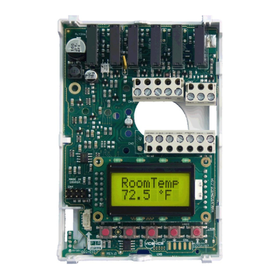
Fig.1
2 Heat / 2 Cool
with economizer
CDIVI-7656B50(X)1
Benefits
⇒ Through the network or smart local occupancy sensing
⇒ Fully integrated advanced occupancy functionality with a PIR
accessory cover
⇒ Adds functionality
⇒ Saves energy during night mode
⇒ Minimizes parameter tampering
⇒ Tamper proof, no need for thermostat guards
⇒ No need to reprogram day/time after power shortage
⇒ Increase flexibility and functionality
⇒ Can be used for lighting and/or economizer override
⇒ Can be used to monitor unit efficiency
⇒ Can be used for all types of establishments
⇒ Excellent retrofit opportunities
⇒ Support single and two stages heat pump with one auxiliary
heat stage
3 Heat / 2 Cool
heat pump
CDIVI-7652H50(X)1
Advertisement

Related Manuals for Distech Controls RT Series


Summary of Contents for Distech Controls RT Series
- Page 1 Hardware Installation Guide Roof Top (RT) Series: ECL-STAT-RT1P, ECL-STAT-RT2P, ECL-STAT-RT2EP, Distech Controls, Inc. ECB-STAT-RT1P, ECB-STAT-RT2P, ECB-STAT-RT2EP, Toll-free: 1-800-404-0043 ECW-STAT-RT1P, ECW-STAT-RT2P, ECW-STAT-RT2EP Tel. International: 450-444-9898 Heat Pump (HP) Series: ECL-STAT-HPP, ECB-STAT-HPP, ECW-STAT-HPP www.distech-controls.com sales@distech-controls.com Product overview The Allure Communicating Roof Top (RT) and Heat Pump (HP) PI thermostat family is specifically designed for single stage and multi-stage control of heating/cooling equipment such as rooftop and self-contained units.
- Page 2 Theory of operation - Rem NSB: remote NSB timer clock input. Will disable the internal scheduling of the thermostat. The scheduling will now The Allure communicating thermostats use a proprietary adaptive be set as per the digital input. The menu part related to logic algorithm to control the space temperature.
- Page 3 Installation Remove security screw on the bottom of thermostat cover. • Open up by pulling on the bottom side of thermostat. • Remove Assembly and remove wiring terminals from sticker. (Fig. 3) • Please note the FCC ID and IC label installed in the cover upon removal of cover •...
- Page 4 Wiring identification & screw terminal arrangement Multistage 1H / 1C Heat Pump Product Name STAT-RT2EP STAT-RT2P STAT-RT1P Product Name STAT-HPP Programmable Programmable Top left terminal block Top left terminal block Top right terminal block Top right terminal block Bottom terminal block Bottom terminal block Econo Scom...
- Page 5 Detailed wiring diagrams for selected models Thermostat Terminals - STAT-RT2EP CDIVI-7656B5XE1 2 Heat / 2 Cool / Economizer / Programmable AU DI1 DI2 Scom Digital Input #1 Jumper J1 See note 1 Digital Input #2 (previous page) Scom Cool Heat 0-10 Vdc Remote Remote...
- Page 6 Remote sensor accessories Model no. Description PDITE-SENSORX0 Wall mounted temperature sensor PDITE-SENSOROX0 Wall mounted temperature sensor w/ override button and occupancy status LED PDIGR-TE200F Series Outdoor temperature sensor PDIGR-TE200D Series Averaging temperature sensor PDIGR-TE200B Series Duct mounted temperature sensor PDITE-SENSOROX0, remote wall mount temperature sensors use 10K NTC thermistors. This sensor can be used for: Various averaging combinations •...
-
Page 7: Summary Specifications
78000 bits per second Network segment length varies depending on wire type. Table 1: Summary of Specifications for a Distech Controls’ LON Network Network Configuration The LonWorks network is designed to support free topology wiring and will accommodate bus, star, loop or any of these topologies. - Page 8 LonWorks Wiring Guide...
- Page 9 LonWorks Wiring Guide Maximum Number Of Devices Up to 64 transceivers are allowed per network segment. If your network requires more than 64 transceivers a repeater is then required to extend your network Maximum Cable Length The maximum length of a chain is related to its transmission speed. The longer the chain, the slower the speed.
-
Page 10: Network Adapter
Grounding Shielded Twisted Pair Cable When using Shielded Twisted Pair, terminate the twisted pair as listed in the previous section and ground the cable shield by using a capacitor, to tie the shield to earth ground, and a large-value resistor to bleed off any static charge on the shield. Tying the shield to earth ground through a capacitor will avoid DC and 50/60Hz ground paths from being formed through the shield. - Page 11 BACnet Wiring Guide Overview Distech Controls uses EIA-485 as the physical layer between their devices and supervisory controllers For clarity we will use the term “Device” to represent any product with an active EIA-485 network connection, including Distech Controls and non-Distech Controls controllers.
- Page 12 Other methods of wiring an EIA-485 network may give unreliable and unpredictable results. There are no troubleshooting methods for these types of networks. Therefore, a great deal of site experimentation may have to be done, making this a difficult task with no guarantee of success. Distech Controls will only support daisy chain configurations.
- Page 13 Using proper cable, the maximum length of an EIA-485 daisy chain is 4000-ft (1200 m). This will only work reliably for data rates up to 100,000 bps. Distech Controls’ maximum data rate is 76,800 bps. If you require a maximum network length of more than 4000 feet, then repeaters are required to extend the network.
- Page 14 BACnet Wiring Guide Figure 5: Correct usage – repeaters are daisy chained to the supervisory controller and separate daisy chains branch from each repeater. Do not install repeaters in series, as this may result in network reliability problems. Figure 6 demonstrates an incorrect use of a repeater in an EIA-485 network.
- Page 15 • Distech Controls thermostats are installed at both ends of the MSTP network: 120 Ohms resistor should be installed at each end. A Distech Controls thermostat is installed at one end of the MSTP network and a 3 party •...
- Page 16 BACnet Wiring Guide Condition of the Status LED Possible Cause Solution BACnet communication NOT active Change MAC address to at default MAC address = 254 another value from 0 to 127 1 short blink Incorrect module has been Incorrect module has been installed installed...
- Page 17 User menu flow chart: If status is: Override MENU Unoccupied schd Y/N If status is: Temporary Occupied Time, Cancel ovrd Y/N Temperat Sys mode Fan mode Clock Schedule Schedule Exit set? Y/N set? Y/N set? Y/N set? Y/N set? Y/N hold Y/N menu Y/N Resume...
- Page 18 Programming and status display instructions 1. Status display The thermostat features a two-line, eight-character display. There is a low level back-light level that is always active and can only be seen at night. When left unattended, the thermostat has an auto scrolling display that shows the actual status of the system. Each item is scrolled one by one with the back lighting off.
- Page 19 2. User programming instructions menu The Allure communicating thermostats feature an intuitive, menu-driven, back-lit LCD display that walks users through the programming steps, making the programming process extremely simple. This menu is typically accessed by the user to set the parameters such as temperature and time events, system mode, fan mode, etc.
- Page 20 A) Override an unoccupied period Override schd Y/N This menu will appear only when the thermostat is in unoccupied mode. The unoccupied mode is enabled either by the internal timer scheduling or by a remote NSB contact via DI1 or DI2. If DI1 or DI2 is configured to operate as a remote temporary override contact, this menu will be disabled.
- Page 21 E) Fan mode setting Fan mode set Y/N This section of the menu is permits the setting of the fan mode operation. Use ▲▼ to set value, Yes key to confirm Fan mode On fan mode Fan is on continuously, even when system mode is OFF. Fan mode Automatic fan mode Auto...
- Page 22 G) Schedule set (4 events) Schedule This section of the menu permits the user to set the whether 2 or 4 events is needed. Each day can be tailored to specific schedules if needed. • 4 events can be programmed per day. •...
- Page 23 H) Clock/Day Settings Clock This section of the menu permits the user to set the time and day. Time setting Day setting Time format setting Time No next → No next → 12/24hrs No = exit set? Y/N set? Y/N set? Y/N Yes down ↓...
- Page 24 30 thermostats per gateway ), be sure you set the SAME channel value both at the gateway and the thermostat(s). Distech Controls recommends using only the 2 last channels ( 25-@ 2575MHz and 26-@ 2580MHz ) The default value of 10 is NOT a valid channel. The valid...
- Page 25 2 = High level Default value = 0 No lock Permanent Resume/ Temporary Occupied and System mode Fan mode Schedules Level Override setpoints using Clock setting Unoccupied setting setting setting scheduling arrows Setpoints Resume RoomTemp Up key (▲) Sys mode Fan mode Schedule Clock...
- Page 26 For multi stage models, heat cph maximum number of cycles that the equipment will turn ON applies to W1 & W2 and OFF in one hour. For heat pump models, heat cph Note that a higher C.P.H will represent a higher accuracy of applies to W1 only control at the expense of wearing mechanical components (Emergency heat )
- Page 27 selects the number of compressor stages H lock Outside air temperature heating Disables heating stage operation based on outdoor air lockout temperature. Default value = 120 °F ( 49 °C ) Function will only be enabled if OS ( outside air temperature sensor ) is connected.
- Page 28 (outside air temperature sensor) is setpoint connected. 34 to 90 °F ( 1.0 to 32.0 °C ) low bp Low balance point In Heating, Cooling or Auto mode, it is the outside air Default value = -12 °F ( -24 °C ) temperature value at which the heat pump operation will be Function will only be enabled if OS cut off.
- Page 29 min pos Minimum position Outside air damper minimum position. Will be active only when fan is on ( G terminal ) and the Default value = 0% internal or remote scheduling is in occupied mode. When internal or remote scheduling is in unoccupied mode and/or fan is off, minimum position will be set to 0% 0 to 100 % = 0 to 10 Vdc output range Outside air...
-
Page 30: Troubleshooting Guide
Troubleshooting guide All models Symptom Possible Cause Corrective Action No display on the Absent or incorrect supply 1. Check power supply voltage between C & RC to be thermostat voltage from 19-30 Vac 2. Check for tripped fuse or circuit breaker Overloaded power Verify that the transformer used is powerful enough transformer... - Page 31 Troubleshooting guide Heatpump models Auxiliary heat does not Wrong mode selected Select emergency heat mode operate Thermostat in Unoccupied Select Override to force the thermostat Occupied mode heating setpoint Anticycle delay active Wait, the anticycling period will end and the equipment will start Heating setpoint is satisfied Raise the Heating setpoint...
-
Page 32: Specifications
Specifications Thermostat power requirements: 19-30 Vac 50 or 60 Hz; 2 VA ( RC & C ) Class 2 RC to RH jumper 2.0 Amps 48 VA maximum Operating conditions: 0 °C to 50 °C ( 32 °F to 122 °F ) 0% to 95% R.H.
Need help?
Do you have a question about the RT Series and is the answer not in the manual?
Questions and answers