Aquagem IP20 Installation And Operation Manual
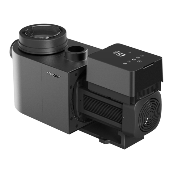
Inverter pool pump
Hide thumbs
Also See for IP20:
- Installation & operation manual (24 pages) ,
- Instruction manual (50 pages)
Advertisement
Advertisement
Table of Contents

Subscribe to Our Youtube Channel
Related Manuals for Aquagem IP20


Summary of Contents for Aquagem IP20
-
Page 2: Table Of Contents
CONTENTS IMPORTANT SAFETY INSTRUCTIONS .......................... 1 2. TECHNICAL SPECIFICATIONS ............................... 2 3. OVERALL DIMENSION (mm) ................................ 2 4. INSTALLATION ....................................3 5. SETTING AND OPERATION ................................5 6. WIFI OPERATION .................................... 13 7. EXTERNAL CONTROL ..................................20 8. PROTECTION AND FAILURE ............................... 21 9. -
Page 3: Important Safety Instructions
IMPORTANT SAFETY INSTRUCTIONS This guide provides installation and operation instructions for this pump. If you have any other questions about this equipment, please consult your supplier. 1.1 When installing and using this electrical equipment, basic safety precautions should always be followed, including the following: •... -
Page 4: Technical Specifications
2. TECHNICAL SPECIFICATIONS Model Advised Voltage Qmax Hmax Circulation (m³/h) Pool (V/Hz) (m³/h) At 8m At 10m Volume (m³) IP20 30-50 220-240/ 0.75 24.0 18.0 19.0 15.0 50/60 IP25 40-70 1.05 27.0 20.0 24.5 21.0 IP30 60-90 29.5 21.0 29.5 26.5... -
Page 5: Installation
4. INSTALLATION 4.1. Pump Location 1) Install the pump as close to the pool as possible, to reduce friction loss and improve efficiency, use short, direct suction and return piping. 2) To avoid direct sunshine, heat or rain, it is recommended to place the pump indoors or in the shade. 3) DO NOT install the pump in a damp or non-ventilated location. - Page 6 4.3. Valves and Fittings Elbows should be no closer than 350mm to the inlet. Do not install 90° elbows directly into the pump inlet/outlet. Joints must be tight. Elbow Return to pool 63mm 350mm Suction 63mm Figure 2 * The pump inlet/outlet union size: optional with 48.5/50/60.3/63mm 2) Flooded suction systems should have gate valves installed on suction and return line for maintenance;...
-
Page 7: Setting And Operation
4.5 Application conditions Ambient temperature Indoor installation, temperature range: -10 - 42℃ 5℃-50℃ Water temperature Salt pools Salt concentration up to 0.5%, i.e 5g/l Humidity ≤90% RH, (20℃±2℃) Installation The pump can be installed max. 2m above water level; Insulation Class F, IP55 5. - Page 8 5.2 Startup: When the power is switched on, the screen will fully light up for 3 seconds, the device code will be displayed, and then it will enter the normal working state. When the screen is locked, only the button will light up;...
- Page 9 5.4 Backwash User can start the backwash or fast re-circulation in any running state by pressing Default Setting range Time 180s Press to adjust from 0 to 1500s with 30 seconds for each step Running capacity 100% 80-120%, enter the parameter setting (see 5.10) Exit backwash: When backwash mode is on, user can hold for 3 seconds to exit, the pump will return to the...
- Page 10 7-22 m³/h. If the set flow is beyond the current adjustable range, the actual achievable flow rate will be displayed after the motor speed is stabilized. The default adjustable flow range for InverPro is as below: Model Default adjustable flow rate range IP20 5-20 m³/h IP25 5-25 m³/h IP30 5-30m³/h...
- Page 11 5.7 Timer mode The pump’s on/off and running capacity could be commanded by timer, which could be programmed daily as needed. Enter timer setting by pressing Press to set the local time Press to confirm and move to time-1 setting Press to choose the desired running periods, running capacity or flow rate (when % icon is flashing, user can change to set the flow rate by pressing...
- Page 12 5.8 Skimmer Mode The skimmer mode enables the pump to skim the water surface, prevents the debris from accumulating, and provides users with a cleaner pool. Hold to enter the preset interface of the skimmer mode, press view the 3 presets, the selected preset will be activated after 8s without operation. User can exit the skimmer mode without activating it by holding in the preset interface.
- Page 13 Skimmer Skimmer Skimmer Preset Time period Remark cycle duration speed Editable in 3 min 100% 7:00 – 21:00 parameter setting 10 min 100% 7:00 – 21:00 Not editable 3 min 7:00 – 21:00 Not editable 5.9 Speed Limit User can set the speed limit of the running capacity to meet the flow requirement of other equipment such as sand filters.
- Page 14 Parameter Default Description Setting Range Address Setting PIN3 100% 30-120%, by 5% increments PIN2 30-120%, by 5% increments PIN1 30-120%, by 5% increments Backwash capacity 100% 80-120%, by 5% increments Control mode of 0: current control Analog Input 1: Voltage control Enable or disable the priming that occurs at 25:enables 0: disables...
-
Page 15: Wifi Operation
6. WIFI OPERATION InverFlow Download Account registration Register by e-mail or third-party application Android Email Registration... - Page 16 b. Third-party application registration Create Home Please set home name and choose the location of the device. (It is recommended to set the location so the weather can be shown in the App for your convenience)
- Page 17 App pairing Please make sure your pump is turned on before you start. Option 1 (Recommended): With Wifi and Bluetooth (Network requirement: 2.4GHz; 2.4Ghz and 5GHz into one SSID; but no separate 5GHz network) 1) Please confirm that your phone is connected to Wifi and your Bluetooth is on. 2) Press for 3 seconds until hearing “Beep”...
- Page 18 Option 2: With Wifi (Network requirement: 2.4GHz only) Please confirm that your phone is connected to Wifi Press for 3 seconds until hearing “Beep” to unlock the screen. Press for 5 seconds until hearing “Beep” then release. Will flash. Click “Add Device”, and then follow the instructions to pair device.
- Page 19 Operation Using Auto Inverter mode: Change flow rate units Error code list Real-time power consumption Turn the control dial to set the flow rate Auto Inverter mode Timer Data On/off Backwash Using Manual Inverter mode: Real-time power consumption Turn the control dial to set the running capacity Manual Inverter mode Data...
- Page 20 Sharing Devices with your family members After pairing, if your family members also want to control the device, please let your family members register “InverFlow” first, and then the administrator can operate as below:...
- Page 21 Feedback If you have any problem while using, welcome to send feedback. Notice: Weather forecast is just for reference; The power consumption data is for reference only, as it may be affected by network problems and imprecision of the calculation. App is subject to updates without notice.
-
Page 22: External Control
7. EXTERNAL CONTROL External control can be enabled via following contacts. If more than one external control is enabled, the priority is as below: Digital Input > RS485 > Panel control Connector for configurable user inputs, including Digital Input and RS485 AC Power input Relay output... -
Page 23: Protection And Failure
Name Color Description PIN 1 Digital Input 4 PIN 2 Black Digital Input 3 PIN 3 White Digital Input 2 PIN 4 Grey Digital Input 1 PIN 5 Yellow Digital Ground PIN 6 Green RS485 A PIN 7 Brown RS485 B Digital input Running capacity is determined by the state of digital input, When PIN4 connects with PIN5, the pump will be mandatory to stop;... - Page 24 If current operating capacity is higher than 70%, the running capacity will be automatically reduced by 10%; If current operating capacity is lower than 70%, the running capacity will be automatically reduced by 8.2 Undervoltage protection When the device detects that the input voltage is less than 197V, the device will limit the current running speed.
-
Page 25: Maintenance
8.4 Error code When the device detects a failure (except for the running capacity reduction strategy and 485 communication failure), it will stop automatically and display the error code. After stopping for 15 seconds, check if the failure is cleared. If cleared, the pump will resume working. Item Error Code Description... -
Page 26: Warranty& Exclusions
4). Empty the trapped refuse from the basket, rinse out the debris if necessary. Note: Do not knock the plastic basket on a hard surface as it will cause damage 5). Inspect the basket for signs of damage, replace it. 6).
Need help?
Do you have a question about the IP20 and is the answer not in the manual?
Questions and answers