
Related Manuals for Avigilon 2.0C-H6X-B


Summary of Contents for Avigilon 2.0C-H6X-B
- Page 1 Installation Guide Avigilon H6X Box Camera Models: 2.0C-H6X-B 6.0C-H6X-B 4.0C-H6X-B 8.0C-H6X-B ...
- Page 2 Legal Notices © 2024, Avigilon Corporation. All rights reserved. A VIGILON, the AVIGILON logo, AVIGILON CONTROL CENTER, and ACC are trademarks of Avigilon Corporation. ONVIF is a trademark of Onvif, Inc. C overed by one or more claims of the patents listed at patentlist.hevcadvance.com. O ther names or logos mentioned herein may be the trademarks of their respective owners. The absence of the symbols ™ and ® in proximity to each trademark in this document or at all is not a disclaimer of ownership of the related trademark. Disclaimer This document has been compiled and published using product descriptions and specifications available at the time of publication. The contents of this document and the specifications of the products discussed herein are subject to change without notice. Avigilon Corporation reserves the right to make any such changes without notice. Neither Avigilon Corporation nor any of its affiliated companies: (1) guarantees the completeness or accuracy of the information contained in this document; or (2) is responsible for your use of, or reliance on, the information. Avigilon Corporation shall not be responsible for any losses or damages (including consequential damages) caused by reliance on the information presented herein. Avigilon Corporation avigilon.com PDF-H6X-B Revision: 1 - EN...
- Page 3 Important Safety Information WARNING Failure to observe the following instructions may result in severe injury or death. Installation must be performed by qualified personnel only, and must conform to all local codes. Any external power supply connected to this product may only be connected to another Avigilon product of the same model series. External power connections must be properly insulated. Do not connect directly to mains power for any reason. CAUTION Failure to observe the following instructions may result in injury to persons or damage to the device. Do not expose the camera directly to high levels of x-ray, laser, or UV radiation. Direct exposure may cause permanent damage to the image sensor. Do not install near any heat sources such as radiators, heat registers, stoves, or other sources of heat. Do not subject the device cables to excessive stress, heavy loads or pinching. Do not open or disassemble the device. There are no user serviceable parts. Refer all device servicing to qualified personnel. Servicing may be required when the device has been damaged (such as from a liquid spill or fallen objects), has been exposed to rain or moisture, does not operate normally, or has been dropped. Do not use strong or abrasive detergents when cleaning the device body. Use only accessories recommended by Avigilon.
- Page 4 This Class B digital apparatus complies with Canadian ICES-003 (B)/NMB-3(B). This equipment has been tested and found to comply with the limits for a Class B digital device, pursuant to part 15 of the FCC Rules. These limits are designed to provide reasonable protection against harmful interference in a residential installation. This equipment generates, uses and can radiate radio frequency energy and, if not installed and used in accordance with the instructions, may cause harmful interference to radio communications. However, there is no guarantee that interference will not occur in a particular installation. If this equipment does cause harmful interference to radio or television reception, which can be determined by turning the equipment off and on, the user is encouraged to try to correct the interference by one or more of the following measures: Reorient or relocate the receiving antenna. Increase the separation between the equipment and receiver. Connect the equipment into an outlet on a circuit different from that to which the receiver is connected. Consult the dealer or an experienced radio/TV technician for help. Changes or modifications made to this equipment not expressly approved by Avigilon Corporation or parties authorized by Avigilon Corporation could void the user’s authority to operate this equipment. To meet the requirements of the EN 50121-4 Railway Applications Standard, use an external power supply or POE injector that is also compliant with EN 50121-4. Please contact Avigilon for assistance regarding supporting equipment. To meet the requirements of the EN 50130-4 Alarm Systems Applications standard, use an external uninterruptible power supply (UPS). This equipment contains a coin cell battery. R isk of fire, explosion, and burns. Do not disassemble, crush, heat above 100°C (212°F), or incinerate. The use of EMC compliant support and auxiliary equipment with this device is required in order to fully comply with the EMC regulatory standards. This product is intended to be supplied by a UL Listed Power Unit marked “Class 2” or “LPS” or “Limited Power Source” with output rated 12-24 VDC, 13 W min. or Power over Ethernet (PoE), 13 W min.
- Page 5 For Korea Disposal and Recycling Information When this product has reached the end of its useful life, please dispose of it according to your local environmental laws and guidelines. European Union: This symbol means that according to local laws and regulations your product should be disposed of separately from household waste. When this product reaches its end of life, take it to a collection point designated by local authorities. Some collection points accept products for free. The separate collection and recycling of your product at the time of disposal will help conserve natural resources and ensure that it is recycled in a manner that protects human health and the environment. ...
-
Page 6: Table Of Contents
Table of Contents Overview Front View Rear View Installation Steps Required Tools and Materials Camera Package Contents Installation Steps Mounting the Camera Connecting Cables Initializing a Camera Username and Password (Optional) Using the USB Wi-Fi Adapter Assigning an IP Address Accessing the Live Video Stream Aiming and Focusing the Camera (Optional) Configuring microSD Card Storage Configuring the Camera Cable Connections Connecting External Power Seamless Failover Connecting to External Devices Connection Status LED Indicator Troubleshooting Network Connections and LED Behavior Resetting to Factory Default Settings Setting the IP Address Using the ARP/Ping Method For More Information Limited Warranty and Technical Support... -
Page 7: Overview
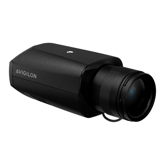
Overview Front View 1. Camera mounts Provides mounting points for the camera. Mounts accept 1/4”-20 x 5/16" max thread UNC bolts commonly found on tripods and mounting brackets. 2. iCS/CS plug port Accepts connection to a iCS or CS lens. 3. Serial number tag Device information, product serial number and part number label. Overview... -
Page 8: Rear View
Rear View 1. I/O connector block Provides connections to external input/output devices. 2. Ethernet port Accepts an Ethernet connection to a network. Server communication a nd image data transmission occurs over this connection. Also r eceives power when it is connected to a network that provides P ower over Ethernet. 3. USB-C port Accepts a USB-C adapter. Only required when using the USB Wi-Fi Adapter. 4. LED indicators Green LED provides information about device operation. Amber LED indicates if there is an active connection in the Ethernet port. For more information, see Connection Status LED Indicator on page 16. 5. microSD card slots Accept microSD cards for onboard storage. 6. Power connector block Accepts a terminal block with either an AC or DC power connection. DC i nput can be either polarity. Only required when Power over Ethernet ... -
Page 9: Installation Steps
Installation Steps Complete the following sections to install the device. Required Tools and Materials Small slotted screwdriver with 5/64” or 2 mm blade width — for connecting power when not using Power over Ethernet. Mounting bracket, enclosure or tripod. Camera Package Contents Avigilon H6X Box Camera Installation Steps Complete the following sections to install the device. Mounting the Camera Camera mounting points are provided on both the top and bottom of the camera body. Use these mounting points to mount the camera on a bracket, in an enclosure, or on a tripod. The mounting points have ¼”-20 UNC threaded holes which allow them to accept standard photographic mounting bolts. Consult the installation instructions provided with the bracket, enclosure or tripod for detailed mounting instructions. Installation Steps... -
Page 10: Connecting Cables
4. Connect a network cable to the Ethernet port (RJ-45 connector). The Link LED indicator will turn on once a network link has been established. 5. Check that the Connection Status LED indicator indicates the correct state. For more information, see Connection Status LED Indicator. Initializing a Camera Username and Password IMPORTANT You must create a user with administrator privileges before the camera is operational. The first user can be created using any of the following methods: Camera's Web Interface: enter the camera's IP address in a web browser to access the web interface. If the camera is in the factory default state you will be redirected to the Add a new user page to create the first user. For more information, see the Avigilon IP Camera Web Interface User Guide. Camera Configuration Tool: cameras discovered in the factory default state will be identified by . Select the Admin Users tab to create the first user. For more information, see the Avigilon Camera Configuration Tool User Guide . Avigilon Unity Video or Avigilon Control Center software version 7.4 or later, or version 6.14.12 or later: when connecting a device in the factory default state, the client software will ask you to create a new user. For more information, see the Avigilon Unity Video Client User Guide or the Avigilon Control Center Client User Guide . Avigilon Cloud Services (ACS) v3.0 or later: when adding a camera you will be asked to create a new user for cameras in the factory default state. For more information, see the Avigilon Cloud Services User Guide . Connecting Cables... -
Page 11: (Optional) Using The Usb Wi-Fi Adapter
TIP If you are connecting your Avigilon camera to a 3rd party VMS, you will need to set up the first user through the camera's Web Interface or Camera Configuration Tool before you connect to the 3rd party VMS. (Optional) Using the USB Wi-Fi Adapter If you have a USB Wi-Fi Adapter (USB-AC56-NA-MSI-B or USB-AC56-EU-MSI-B), attach it to the camera's USB-C port to access the camera's mobile web interface. After you connect to the Wi-Fi signal broadcast by the adapter, you can access the mobile web interface from any mobile device using the following address: http://camera.lan For more information about configuring the camera from the mobile web interface see USB Wi-Fi Adapter System User Guide . NOTE The camera will reserve the 10.11.22.32/28 subnet for internal use while the USB Wi-Fi Adapter is plugged in. Assigning an IP Address The device automatically obtains an IP address when it is connected to a network. NOTE If the device cannot obtain an IP address from a DHCP server, it will use Zero Configuration Networking (Zeroconf) to choose an IP address. When set using Zeroconf, the IP address is in the 169.254.0.0/16 subnet. The IP address settings can be changed using one of the following methods: Device's web browser interface: http:// <camera IP address>/ . Network Video Management software application (for example, the Avigilon Unity Video software). Setting the IP Address Using the ARP/Ping Method on ARP/Ping method. For more information, see page 18. NOTE When you log in the first time, the camera will be in a factory default state and no password is required. You must create a user with administrator privileges before the device is operational. ... -
Page 12: Accessing The Live Video Stream
Accessing the Live Video Stream Live video stream can be viewed using one of the following methods: The mobile web interface using the USB WiFi Adapter. For more information, see (Optional) Using the USB Wi-Fi Adapter. Web browser interface: http:// < camera IP address>/ . Network Video Management software application (for example, the Avigilon Unity Video software). NOTE When you log in the first time, the camera will be in a factory default state and no password is required. You must create a user with administrator privileges before the device is operational. For more information, see Initializing a Camera Username and Password on page 1. Aiming and Focusing the Camera Use the camera web browser interface or the Avigilon Control Center software to aim and focus the camera. Consult the software user guide for more information. For iCS lens: 1. In the Image and Display settings area, use the Zoom controls to set the zoom position for the camera. 2. Focus the camera: a. Click Auto Focus to focus the lens. b. If the preferred focus was not achieved, use the focus near and far buttons to adjust the focus. For CS lens: NOTE These steps should be completed any time a CS lens is installed or replaced. If a CS lens is not first focused correctly with manual focus adjustment, Auto Focus may not be able to perform automatic focusing. 1. Connect the CS lens to the camera and then power up the camera. The camera should automatically detect it. -
Page 13: (Optional) Configuring Microsd Card Storage
For the location of the microSD card slots, see Overview on page 7. It is recommended that the microSD card have a write speed of class 10 or better. If the microSD card does not meet the recommended write speed, the recording performance may suffer and result in the loss of frames or footage. 1. Insert one or two microSD cards into the slots on the back of the camera. Do not remove microSD cards while the camera is powered on. 2. Access the camera’s web interface to enable the onboard storage feature. For more information, see the Avigilon IP Camera Web Interface User Guide . Configuring the Camera Once installed, use one of the following methods to configure the camera: If you have installed multiple cameras, you can use the Camera Configuration Tool to configure common settings. For more information, see the Camera Configuration Tool User Guide . If the camera is connected to the Avigilon Control Center system, you can use the client software to configure the camera. For more information, see the Avigilon Control Center Client User Guide. If the camera is connected to the Avigilon Unity Video system, you can use the client software to configure the camera. For more information, see the Avigilon Unity Video Client User Guide . If the camera is connected to a third-party network management system, you can configure the camera's specialty features in the camera's web browser interface. For more information, see the Avigilon IP Camera Web Interface User Guide. (Optional) Configuring microSD Card Storage... -
Page 14: Cable Connections
Cable Connections Connecting External Power If PoE is not available, the camera needs to be powered through the removable power connector block. Refer to the diagrams in this guide for the location of the power connector block. The power consumption information is listed in the product specifications. To connect power to the power connector block, complete the following steps: 1. Remove the power connector block from the camera. 2. Remove the insulation from ¼” (6 mm) of the power wires. Do not nick or damage the wires. 3. Insert the two power wires into the two terminals on the power connector block. The connection can be made with either polarity. Use a small slotted (5/64” or 2 mm blade width) screwdriver to loosen and tighten the terminals. 4. Attach the power connector block back into the camera. Seamless Failover If the camera has power available from both an external Aux power supply and a PoE PSE (Power Sourcing Equipment) device, the camera will draw power from Aux. In the event that the camera loses power from the preferred Aux power supply it can transition to drawing power from the PoE PSE device. This camera is capable of Seamless Failover, allowing the camera to transition between PoE and auxiliary power sources without any interruption of camera operation or video recording. This is mainly useful if you want redundant power sources so that backup power will be available if one power source goes down. Cable Connections... -
Page 15: Connecting To External Devices
Connecting to External Devices External devices are connected to the camera through the I/O terminal block. The pinout for the I/O terminal block is shown in the following diagram: Figure 1: Example application. 1. Digital Output 2. Ground 3. Digital Input 4. Voltage Output (Max 50 mA) 5. Audio Ground 6. Audio Input (line level) 7. Audio Output (line level) 8. RS-485 B — Inverting RS-485 pin for controlling external equipment. 9. RS-485 A — Non-inverting RS-485 pin for controlling external equipment. 0 — External Device * — Relay ** — Switch M — Microphone ... -
Page 16: Connection Status Led Indicator
Obtaining One short flash Attempting to obtain an IP address. IP Address every second Discoverable Two short flashes Obtained an IP address but not connected to the Network Video every second Management software. Upgrading Firmware Two short flashes Updating the firmware. and one long flash every second Connected Connected to the Network Video Management software, a Unity Video Server, or an ACC™ Server. The default connected setting can be changed to Off using the camera's web user interface. For more information see the Avigilon IP Camera Web Interface User Guide . Troubleshooting Network Connections and LED Behavior NOTE For any of the below LED behaviors, ensure that the camera is getting power and is using a good network cable before trying another solution. LED Behavior Suggested Solution Green LED is off and amber is on Perform a factory reset of the camera using the physical firmware revert button. Resetting through the camera's web interface will not produce the desired result. Both LEDs are off and the camera is not Check the General setup page in the camera's web interface to connected or streaming video ensure the LEDs are not disabled. If the LEDs are not disabled, perform a factory reset of the camera using the physical firmware revert button. Resetting through the camera's web interface will not produce the desired result. -
Page 17: Resetting To Factory Default Settings
Resetting to Factory Default Settings If the device no longer functions as expected, you can choose to reset the device to its factory default settings. Use the firmware revert button to reset the device. The firmware revert button is shown in the following diagram: Resetting the camera will not affect video that has been recorded to the microSD card. Figure 2: The firmware revert button on the rear of the camera 1. Ensure the device is powered on. 2. Using a straightened paperclip or similar tool, gently press and hold the firmware revert button. 3. Release the button after three seconds. CAUTION Do not apply excessive force. Inserting the tool too far may damage the camera. Resetting to Factory Default Settings... -
Page 18: Setting The Ip Address Using The Arp/Ping Method
Setting the IP Address Using the ARP/Ping Method NOTE The ARP/Ping Method will not work if the Disable setting static IP address through ARP/Ping method checkbox is selected in the camera's device's web browser interface. For more information, see the Avigilon IP Camera Web Interface User Guide . Complete the following steps to configure the camera to use a specific IP address: 1. Locate and make note of the MAC Address (MAC) listed on the Serial Number Tag for reference. 2. Open a Command Prompt window and enter the following commands: a. arp -s <New Camera IP Address> <Camera MAC Address> For example: arp -s 192.168.1.10 00-18-85-12-45-78 b. ping -l 123 -t <New Camera IP Address> For example: ping -l 123 -t 192.168.1.10 3. Reboot the camera. 4. Close the Command Prompt window when you see the following message: Reply from <New Camera IP Address>: ... -
Page 19: For More Information
For More Information Additional information about setting up and using the device is available in the following guides: Avigilon Control Center Client User Guide Avigilon IP Camera Web Interface User Guide Camera Configuration Tool User Guide Designing a Site with Avigilon Video Analytics These guides are available on help.avigilon.com and on the Avigilon website: avigilon.com/support. For More Information... -
Page 20: Limited Warranty And Technical Support
Limited Warranty and Technical Support Avigilon warranty terms for this product are provided at avigilon.com/warranty. Warranty service and technical support can be obtained by contacting Avigilon Technical Support: avigilon.com/contact. Limited Warranty and Technical Support...
Need help?
Do you have a question about the 2.0C-H6X-B and is the answer not in the manual?
Questions and answers