
Related Manuals for Cavli Wireless C10QM


Summary of Contents for Cavli Wireless C10QM
- Page 1 C10QM/C20QM EVK User Manual Cavli C10QM/C20QM EVK User Manual External Release Version 1.1 www.cavliwireless.com www.cavliwireless.com...
- Page 2 COPYRIGHT THE INFORMATION CONTAINED HERE IS PROPRIETARY TECHNICAL INFORMATION OF CAVLI WIRELESS TRANSMITTING, REPRODUCTION, DISSEMINATION AND EDITING OF THIS DOCUMENT AS WELL AS UTILIZATION OF THE CONTENT ARE FORBIDDEN WITHOUT PERMISSION. OFFENDERS WILL BE HELD LIABLE FOR PAYMENT OF DAMAGES.
-
Page 3: Table Of Contents
2 Interfaces ..........................9 2.1 Chapter Overview ..............................9 2.2 EVK Layout ..................................9 2.3 Pin Layout ..................................10 2.3.1 P1 Pinout – C10QM/C20QM ..........................10 3 Component Description ...................... 12 3.1 Antenna ....................................12 3.1.1 LTE Antenna .................................. 12 3.1.2 Diversity Antenna .............................. - Page 4 C10QM/C20QM EVK User Manual 3.8.7 WLAN_EN ..................................20 3.8.8 STATUS ................................... 20 3.8.9 WWAN_STATE................................. 20 3.8.10 RESOUT_N ................................20 3.8.11 WAKEUP ..................................20 3.9 USB- UART Converter ............................21 3.10 50 Pin Connector ..............................21 3.11 USB Boot Button ..............................22 3.12 Reset Button ................................
- Page 5 Figure 4: C10QM/C20QM EVK JTAG Interface ...................... 14 Figure 5: C10QM/C20QM EVK SD interface ......................15 Figure 6: C10QM/C20QM EVK Micro SD socket ....................16 Figure 7:C10QM/C20QM EVK ethernet interface ....................17 Figure 8: C10QM/C20QM EVK LCD interface ......................18 Figure 9 : C10QM/C20QM EVK LED indicators ......................
- Page 6 C10QM/C20QM EVK User Manual VERSION HISTORY Version Edit Date Initial Version 09-08-2023 Updated features based on latest hardware 11-09-2023 www.cavliwireless.com...
-
Page 7: Introduction
This document aims to familiarize the reader on the different functionalities and interfaces of C10QM/C20QM Evaluation board. It also helps the customer in getting started with the C10QM/C20QM EVK. The EVK is a tool designed for engineers, programmers and developers who are looking to: •... -
Page 8: Interfaces
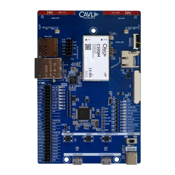
C10QM/C20QM EVK User Manual Interfaces 2.1 Chapter Overview Description: This chapter contains all the necessary information on C10QM/C20QM EVK Interfaces and Pin-outs. 2.2 EVK Layout Figure 1: C10QM/C20QM EVK Layout www.cavliwireless.com... -
Page 9: Pin Layout
C10QM/C20QM EVK User Manual 2.3 Pin Layout 2.3.1 P1 Pinout – C10QM/C20QM Pin No. Pin name Pin No. Pin name P_SYNC DBG_RX P_IN DBG_TX P_OUT U3_RX P_CLK U3_TX P_INT U3_CTS MOSI U3_RTS U4_RX MISO U4_TX 3.3V 1.8V(VCCB) BOOT ADC1 ADC2... - Page 10 C10QM/C20QM EVK User Manual WAKE GPIO42 WLAN GPIO43 FLIGHT GPIO44 GPIO47 GPIO45 PWRLCD GPIO46 www.cavliwireless.com...
-
Page 11: Component Description
Figure 2: C10QM/C20QM EVK Antennas 3.1.1 LTE Antenna C10QM/C20QM EVK comes with an integrated LTE antenna from Ignion. This part appears on the top left corner labelled as NN03_310. It offers worldwide coverage and works in multiple frequency regions. The frequency bands covered are Low (698-960 MHz), Mid (1710-2170 MHz) and High bands (2300- 2690 MHz). -
Page 12: Diversity Antenna
C10QM/C20QM EVK User Manual 3.1.2 Diversity Antenna C10QM/C20QM EVK comes with an integrated chip antenna (NN03_310) for diversity. Also, in every mini PCIe cards, SMA connectors are provided to connect an external antenna if the user wants to. 3.1.3 GNSS Antenna Users can connect an external GNSS antenna using the U.FL connector on the EVK. -
Page 13: Jtag Interface
C10QM/C20QM EVK User Manual 3.3 JTAG Interface The user can program the module using JTAG. Figure 4: C10QM/C20QM EVK JTAG Interface www.cavliwireless.com... -
Page 14: Sd Interface
C10QM/C20QM EVK User Manual 3.4 SD Interface This interface is used to access the SDC of the C10QM/C20QM. Figure 5: C10QM/C20QM EVK SD interface www.cavliwireless.com... -
Page 15: Micro Sd Card Socket
C10QM/C20QM EVK User Manual 3.5 Micro SD Card Socket The C10QM/C20QM EVK provides a micro-SD card socket. The user can insert a micro-SD card to the connector and access the files using the module. Figure 6: C10QM/C20QM EVK Micro SD socket... -
Page 16: Ethernet
Figure 7:C10QM/C20QM EVK ethernet interface 3.6.1 Ethernet chip C10QM/C20QM EVK has an ethernet interface. AR8033-ALIA-R is an integrated 10/100/1000 ethernet transceiver. A magnetic modular integrated jack is used to interface the AR8033-ALIA-R with RJ45 interface. The Integrated magnetic modular RJ45 Jack used is KLA1S109-43 LF. -
Page 17: Lcd Interface
C10QM/C20QM EVK User Manual 3.7 LCD Interface This is a MIPI DBI-2 Type B interface used for LCD interfacing. Figure 8: C10QM/C20QM EVK LCD interface www.cavliwireless.com... -
Page 18: Led Indicators
C10QM/C20QM EVK User Manual 3.8 LED Indicators Figure 9 : C10QM/C20QM EVK LED indicators 3.8.1 3.8 V This LED indicates 3.8V power input. 3.8.2 3.3 V This LED indicates 3.3V power input. www.cavliwireless.com... -
Page 19: Pwr_Lcd_En
C10QM/C20QM EVK User Manual 3.8.3 1.8 V This LED indicates 1.8V voltage source. 3.8.4 PWR_LCD_EN This LED is used to indicate power when LCD is enabled. 3.8.5 UIM_SEL This LED is used to indicate USIM selection. 3.8.6 FLIGHT This LED indicates flight mode of the module. -
Page 20: Usb- Uart Converter
3.9 USB- UART Converter A 48 pin FT4232 converter is used in the DDK. For more details refer UART interface section. Figure 10: C10QM/C20QM EVK USB UART Convertor 3.10 50 Pin Connector The 50-pin connector enables the user to access all the available interfaces. The signals from the 80-pin connector are available in this 50-pin connector. -
Page 21: Usb Boot Button
C10QM/C20QM EVK User Manual Figure 11: C10QM/C20QM EVK 50 pin connector 3.11 USB Boot Button This button is used to enter into bootloader. www.cavliwireless.com... -
Page 22: Reset Button
C10QM/C20QM EVK User Manual Figure 12: C10QM/C20QM EVK USB boot button 3.12 Reset Button This button is used to reset the module. www.cavliwireless.com... -
Page 23: Power Button
C10QM/C20QM EVK User Manual Figure 13: C10QM/C20QM EVK Reset button 3.13 Power Button This button is used to power on the module. www.cavliwireless.com... -
Page 24: Power Switch
C10QM/C20QM EVK User Manual Figure 14: C10QM/C20QM EVK power button 3.14 Power Switch The power switch is used to power on and off the EVK board. www.cavliwireless.com... -
Page 25: Power Input- (Type C)
C10QM/C20QM EVK User Manual Figure 15: C10QM/C20QM EVK Power switch 3.15 Power Input- (Type C) It is recommended to use a 5V/2A adapter for the input power supply. The user can also use PC USB port www.cavliwireless.com... -
Page 26: Usb Interface
C10QM/C20QM EVK User Manual to power the modules. Figure 16: C10QM/C20QM EVK Power input 3.16 USB Interface • Micro-USB Interface to access the module’s USB 2.0 Interface . www.cavliwireless.com... -
Page 27: Uart Interface
C10QM/C20QM EVK User Manual Figure 17: C10QM/C20QM EVK USB Interface 3.17 UART Interface When the user connects a USB cable to the UART micro-USB port, four ports will be displayed in the serial terminal. In which the first one is debug port and the third one is the AT Port. -
Page 28: Figure 18: C10Qm/C20Qm Evk Uart Interface
C10QM/C20QM EVK User Manual Figure 18: C10QM/C20QM EVK UART interface www.cavliwireless.com... -
Page 29: Setup Guide
C10QM/C20QM EVK User Manual Setup Guide Given below are the various steps involved in the connection of C10QM/C20QM with a PC: 1. Place the EVK on an insulated platform. 2. Connect the GNSS Antenna (if needed) to the corresponding UFL Connectors.
Need help?
Do you have a question about the C10QM and is the answer not in the manual?
Questions and answers