Table of Contents
Advertisement
Quick Links
Advertisement
Table of Contents

Related Manuals for SIGRIST TurBiScat 2 Ex


Summary of Contents for SIGRIST TurBiScat 2 Ex
- Page 1 TurBiScat 2 Ex Bedienungsanleitung sigrist.com...
- Page 2 © Copyright provisions (Copyright © This document was written by Sigrist-Photometer AG. The copyright is held by Sigrist-Photometer AG. Copying, modifying or translating the contents or passing it on to third parties is only permitted with the agree- ment of Sigrist-Photometer AG.
-
Page 3: Table Of Contents
Restrictions on use ......................... 7 Foreseeable misuse ....................... 7 Warnings .......................... 7 Residual risks ......................... 8 Device data ....................... 9 TurBiScat 2 Ex........................ 9 Nameplate .......................... 9 Scope of supply and accessory parts................... 10 Specification sheet ....................... 10 Mounting ......................... 13 Requirements ........................ - Page 4 Table of contents 9.3.2 Menu: Simulation .......................... 29 9.3.3 Menu: Recalibration ........................... 30 9.3.4 Menu: History............................. 30 9.3.5 Menu: System info .......................... 30 Advanced configuration mode .................... 31 9.4.1 Menu: IO module EG_IO ........................ 31 9.4.2 Menu: WLAN............................ 34 9.4.3 Menu: Display ............................
-
Page 5: About This Document
NOTE Non-compliance with the instruction manual Sigrist-Photometer AG accepts no liability for damage resulting from failure to observe the instruction manual. Storage of the instruction manual The instruction manual is an integral part of the unit. It must be available to staff at all times. - Page 6 About this document Symbol Name Function [Ok] Button Buttons used for navigation in the SIGRIST-Webinterface. Device-specific Placeholder Stands as a placeholder for unspecified, changing term. 6 / 62...
-
Page 7: Your Safety
Your Safety Your Safety Intended use The TurBiScat 2 Ex is designed for turbidity measurement in liquids in explosion hazard areas of zone 1 (Ex db IIC T3/T4/T5/T6 Ga/Gb). Possible applications can be found in the following areas: Areas of application... -
Page 8: Residual Risks
Your Safety Residual risks The device was built in accordance with the applicable standards and the recognized safety rules. It corresponds to the state of the art. Nevertheless, injuries to persons, damage to the device or material damage to the infra- structure may occur during use. -
Page 9: Device Data
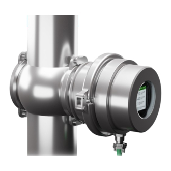
Device data Device data TurBiScat 2 Ex Explosive area TurBiScat 2 Ex WLAN connection WLAN input device explosion tested Operating device or control system Non explosive area Connecting cable explosion-protected Earth conductor terminal Nameplate Manufacturer Device type Serial number U: Service voltage... -
Page 10: Scope Of Supply And Accessory Parts
Scope of supply and accessory parts Please refer to the sales documents for the detailed scope of supply. Standard scope of supply Designation Variant View ® TurBiScat 2 Ex VARINLINE connection Flange connection ® Blanking plate with cone and O-ring VARINLINE... - Page 11 The flow must be at least 0.2 l/min. at a coolant tempera- ture of max. 20 °C. Max. pressure TurBiScat 2 Ex (window insert): 2 MPa (20 bar) at max. 180 °C. ® VARINLINE connection with blanking plate (art. no.: 122037): Note specification.
- Page 12 Device data Photometer Values Dimension Ø 134.5 x 139 mm ® Tube connections VARINLINE connection: DN 40 ... DN 150, 1 1/2" ... 6" Flange connection with special measuring cell: Ø 88.9 x 82.5 mm weld spigot Weight 4.7 kg Protection class IP 66 Display...
-
Page 13: Mounting
Mounting Mounting Requirements For the mounting of the photometer and its additional components, the detailed dimension drawings must be ob- served. The following provisions apply to the applications. The photometer must be installed in the line at least 2 m away from sight glass or other sources of interfering light. -
Page 14: Connecting The Cooling Unit
Mounting Connecting the cooling unit Use commercially available silicone hoses (interior diameter 6 mm) for the cooling unit. Ensure coolant flow from bottom to top. Ensure a flow rate of min. 0.2 l/min. Mount coolant supply line to the inlet Mount coolant return line to the outlet Open the coolant supply line and check for tightness. -
Page 15: Electrical Installation
Electrical installation Electrical installation DANGER Danger due to improper connection of the operating voltage. Improper connection of the electrical service voltage can be life-threatening. The system can also be damaged in the process. Connection must be carried out by a specialist in accordance with local regulations. Install a disconnecting device near the power supply to disconnect the device from the mains. - Page 16 Electrical installation Cable wh/gn wh/og wh/bu wh/bn strands Function 10/100BaseT POE Mode A POE Mode B 16 / 62...
-
Page 17: Operation
Operation Operation The device can be operated via the proximity sensor (TOUCH), with the finger on the device display or with WiFi- capable devices. Display 7.1.1 Operating elements You can switch between the different menu items by touching them. Short touch (<0.5s): navigate between menus Long touch (1...2s): Navigate within a menu For the input to be recognized, the finger must be lifted at least 5 cm after the touch. -
Page 18: Operation Sigrist-Webinterface
Operation Operation SIGRIST-Webinterface 7.2.1 SIGRIST-Webinterface Menu settings Status Current measured values 7-day logger diagram LED temperature Sensor internal temperature Sensor humidity Status inputs Status outputs 18 / 62... -
Page 19: Commissioning
Commissioning Commissioning Ensure correct mounting and electrical installation. Establish service voltage. w Start screen appears. Rotate display if necessary Display can only be rotated during start display. Without action, display changes to measuring mode after 15 seconds. Touch the proximity sensor for a long time. w Display rotates by 90°. - Page 20 Access URL with QR code. Alternative: Open browser (e.g. Chrome, Safari). Enter the displayed URL (192.168.10.1). w Login screen appears. Log in to SIGRIST-Webinterface Log in without password. Recommendation: Secure access to the SIGRIST-We- binterface with a password. 20 / 62...
-
Page 21: Settings
Settings Settings Displays on the photometer Info for navigation [} 17]. Displays on the photometer Sensor status Set standard display see menu Display. No fault Warning Error 21 / 62... - Page 22 Settings Start display For detailed information, see Commissioning/ Operating elements Touch for a long time (1... 2 s): Rotates the display (only possible during start display). Touch briefly (<0.5 s): Navigate between menu items. Software version No action (15 s): Display changes to measuring mode. Start display Symbol for rotating the display (only possible during start display)
- Page 23 Settings Graphic display Measurement info WLAN status (Off → grey/ On → light) Period: Function of how the measuring value is dis- played. Measuring value display with three time periods: 1 hour/ 1 day/ 7 days Channel name with measuring value, unit and dis- played measuring range.
- Page 24 DHCP: On/ Off Assigned IP address MAC address Station name of the unit Transparent Ethernet: 1: Sigrist web server/ 0: Web server of gateway module Profibus DP module: WLAN status (Off → grey/ On → light) Module status: Grey → Inactive/ Blue → Active in idle mode/ Green →...
- Page 25 Settings WLAN connection WLAN status (Off → grey/ On → light) Connection status SSID: Name of the WLAN network DHCP: On/ Off Assigned IP address Gateway address Connected devices WLAN base station (AP) WLAN connection (STA) LAN connection (POE, Profinet) Status Meter status WLAN status (Off →...
- Page 26 Settings Contact information For display adjustment, see System menu [} 37]. WLAN status (Off → grey/ On → light) Manufacturer of the unit Telephone number of the supplier Email address of the supplier Web address of the supplier System info WLAN status (Off → grey/ On → light) Device type Serial number Designation of the measuring point/device...
-
Page 27: Sigrist-Webinterface
Settings Sigrist-Webinterface 9.2.1 Homepage After logging in, the Sigrist-Webinterface appears in the measuring mode. Open menu Start menu Photometer settings Simple/ [} 29] Extended [} 31] configuration mode Logging on/off Change language Open logger diagram 9.2.2 First steps Open menu (1). Select «language» (2). -
Page 28: Change Configuration Mode
Settings 9.2.4 Change configuration mode Set the toggle switch from Simple to Advanced or from Advanced to Simple. w The corresponding menu structure appears. 28 / 62... -
Page 29: Simple Configuration Mode
0° Orientation of the display. «Access code» Enter access code (numbers only). Used to protect against unauthorised access. «Designation» Enter the name of the measurement point identification in the Sigrist-Webinterface (max. 13 characters). 9.3.2 Menu: Simulation Parameter Values Default value «Measured value mode»... -
Page 30: Menu: Recalibration
Settings 9.3.3 Menu: Recalibration Submenu: Recalibration C1 ... Cn Parameter Values Default value «Nominal value» Device-specific Enter the value of the control unit belonging to the unit or the nominal value for the formazine solution. «Actual value» Current measured value Current measured value. -
Page 31: Advanced Configuration Mode
«Version Sensor» Software version of the sensor controller. «Version Comm» Software version of the communication controller. «Version Web» Software version of the interface for the Sigrist-Webinterface. «Update firmware» [Check online] [Select file...] [Upload & update] Check online: With an Internet connection, it is possible to check whether new software is available. A valid DNS server address must be available in the communication module. - Page 32 Settings IO Configuration\ General Parameter Values Default value «0/4mA...20 mA» 0-20 mA/ 4-20 mA 4-20 mA Set current range for measured value output. «For service» 0 value/ Last value Last value Set the measured value output in service mode. «Max. value» 20 ...
- Page 33 Settings Parameter Values Default value «Baud rate» 4800/ 9600/ 19200/ 38400, 57600/ 115200 baud 115200/ 230400 baud Set the baud rate of the Modbus interface (baud rate in bits/s). «Parity» None/ Even/ Odd Even Set the parity bits of the Modbus interface. «Stop bit»...
-
Page 34: Menu: Wlan
Settings Parameter Values Default value «Source» C1 ... Cn/ M1 ... Mn/ Humidity C1 Turb90 Available sources. «Mode» Inactive/ Exceed./ Undershoot. Inactive Set whether the limit value function is inactive or should react to undercutting or exceeding the limit value. «Upper limit»... -
Page 35: Menu: Display
Settings WLAN\ WLAN connection Parameter Values Default value «Active» On/ Off Switch the WLAN connection on/off. «DHCP» On/ Off Automatic assignment of IP addresses. DHCP On: Assigned IP address, gateway address and subnet mask are displayed. DHCP Off: Enter IP address, gateway addr., sub-net mask and DNS server manually. «Set up»... -
Page 36: Menu: Sensor Check
Settings Parameter Values Default value «Display brightness» 0 ... 100% Set the brightness of the display on the photometer. NOTICE! Low brightness reduces power consumption and extends the life of the display. «Power-saving mode» 0 ... 65535 s 300 s Time period after which the display brightness on the photometer is reduced without manipulation. -
Page 37: Menu: System
During an online firmware update, operating hours, temperatures, voltages, intensities of the light sources and the error history are transmitted. «Contact information» Sigrist-Photometer AG Enter line 1 of the contact information (max. 47 characters). «Contact information» Switzerland Enter line 2 of the contact information (max. 47 characters). -
Page 38: Menu: Math. Channels
Settings Parameter Values Default value «Integration» 0 ... 60000 s 10 s Set the integration time for the forming of measured values. The integration is done via a low-pass filter. The set integration time corresponds to the step response of the measured value from 0 ... -
Page 39: Menu: Measuring Info
Settings Parameter Values Default value «Unit» Enter the unit (max. 7 characters). «Coeff. a/b/c/d» -5000 ... 999999 Device-specific Set the coefficient value a/b/c/d within the function. 9.4.8 Menu: Measuring info Parameter Values Default value «Measuring info» View various values of the current measuring operation. Measured values C1..C4/ Math values M1..M2/ Inner temperature/ LED temperature/ Humidity value/ +5V ana- logue voltage/ -10V analogue voltage Logger diagram... -
Page 40: Field Bus
Settings Settings Set the measuring ranges per channel (drop-down menu). Changes are adopted for the graphic display on the unit. Measured value display cursor position Measured value display refers to cursor position (3). The minimum (double arrow down), maximum (double arrow up) and average values are displayed. -
Page 41: Modbus Tcp General
Settings Register Address Data type Function Values 30003 0x0002 Real 32-bit Intel single precision bits Measured value 15-0 channel 1 30004 0x0003 Real 32-bit Intel single precision bits 31-16 30005 0x0004 Real 32-bit Intel single precision bits Measured value 15-0 channel 2 30006 0x0005... -
Page 42: Servicing
CAUTION Unit damage due to lack of maintenance Lack of or inadequate maintenance as well as the use of non-original Sigrist spare parts may damage the device and lead to measurement errors. Always carry out servicing work according to the servicing schedule. -
Page 43: Replace Desiccant
Servicing 10.2 Replace desiccant NOTE Condensation inside the electronics When the sample medium is cold, humidity can condense when the unit is opened and damage the electronics. Only open the photometer when the medium temperature is ≥ room temperature. If the desiccant needs to be replaced frequently, have the tightness checked by a service technician. DANGER! Explosion hazard! Disconnect the service voltage and disconnect all conductors. -
Page 44: Clean Sensor Head
Servicing 10.3 Clean sensor head NOTE Improper cleaning of the sensor head Cleaning with unsuitable cleaning agents can cause damage to windows and thus affect the measuring accuracy of the photometer. Do not use abrasive cleaning agents. Alcohol or soap, for example, are suitable. Soiling of the sensor head is largely compensated for by the photometer. -
Page 45: Cleaning The Sensor Head (Flange Connection)
Servicing ® Installing the photometer on the VARINLINE connection Fit the photometer including seal with clamp ® ring on VARINLINE connection (3). Ensure that the groove points in the flow direction. 10.3.2 Cleaning the sensor head (flange connection) Removing the photometer (flange connection) WARNING! The photometer must not be removed without draining the process line beforehand! Drain... -
Page 46: Calibration Check
Servicing Installing the photometer (flange connection) Fasten photometer crosswise to special measur- ing cell with 4 screws (4). Tighten the screws (tightening torque min. 30 Nm, max. 35 Nm). Ensure that the groove points in the flow direction. 10.4 Calibration check Calibration check, general An adjustment leads to deviations from the previous measured value. -
Page 47: Overview Of Control Units
Servicing 10.4.1 Overview of control units ® A distinction is made between VARINLINE connection and flange connection (2). The control units are equipped with the corresponding connection adapter. Overview of control units ® VARINLINE connection Flange connection ® Clamp ring VARINLINE Flange connection screws (4 x) ®... -
Page 48: Carry Out Calibration Check With Control Unit
Servicing 10.4.3 Carry out calibration check with control unit NOTE Use of an incorrect control unit. The use of an incorrect control unit can falsify the calibration check. The control unit number must match the serial number of the unit. ®... - Page 49 Servicing Remove solid reference from control unit When testing with formazine (C1, C2) and zeroing (C3, C4), remove the solid reference from the control unit (Calibration check [} 46]). Loosen two screws (1). Remove the solid reference from the control unit. Put on control unit Align pin with recess (2).
- Page 50 Servicing Fastening the control unit (flange connection) Fasten control unit with four screws (2). Filling the control unit Fill control unit with test medium via filling funnel (3). Make sure that the level indicator is filled up to approx. half. Bubble formation can be prevented by filling slowly.
-
Page 51: Replace Seals
Servicing Complete the calibration check Empty control unit and remove from photometer. ® Install photometer Installation on VARINLINE con- nector} 13] installation flange connection [} 13]). Put photometer into operation. Align solid reference with pins and fasten. Clean the control unit [} 47]. w The calibration check is completed. -
Page 52: Replace Seal (Flange Connection)
Servicing ® Installing the photometer on the VARINLINE connection Fit the photometer including seal with clamp ® ring on VARINLINE connection (3). Ensure that the groove points in the flow direction. 10.5.2 Replace seal (flange connection) Removing the photometer (flange connection) WARNING! The photometer must not be removed without draining the process line beforehand! Drain... -
Page 53: Spare Parts
Servicing Installing the photometer (flange connection) Fasten photometer crosswise to special measur- ing cell with 4 screws (4). Tighten the screws (tightening torque min. 30 Nm, max. 35 Nm). Ensure that the groove points in the flow direction. 10.6 Spare parts Article number Designation Comments... -
Page 54: Troubleshooting
Troubleshooting Troubleshooting 11.1 Isolate faults Malfunction Measure No display Check service voltage. Error message in display Analyse error message (Warning/error/priority messages). Measured value seems wrong Ensure correct operating conditions of the sample medium. Check calibration. Check correct mounting. Ensure that servicing duty has been carried out correctly. Perform sensor check. -
Page 55: Warning / (Prio) Error Messages
Troubleshooting 11.2 Warning / (prio) error messages In the event of a malfunction, either the measuring value or a corresponding status symbol is displayed ac- cording to the parameterization. By touching the proximity sensor for a long time, the detailed information appears. Warning messages System remains in operation. -
Page 56: Fault Messages
Troubleshooting Code Message Description Possible causes ADJUSTMENT Adjustment of the device could not Device is soiled be carried out Nominal value for adjustment does not match the value of the medium SENSOR CHECK Automatic sensor check failed Too much external light near the measuring cell (e.g. -
Page 57: Prio Fault Messages
Troubleshooting Code Message Description Possible causes LIGHT SOURCE 2 Detector for monitoring the light Defective light source source is not receiving light from the Contact service technician. corresponding light source. 11.5 Prio fault messages The following Prio fault messages may be displayed during operation. Code Message Description... -
Page 58: Repairs
Repairs Repairs 12.1 Replace basic device DANGER! Explosion hazard! Disconnect the service voltage and disconnect all conductors. Loosen allen screw (5) Remove the protective sleeve (4) from the clamp ring (3) Loosen and remove the clamp ring (3) Remove the old basic device from the sensor head. -
Page 59: Returns
Returns Returns Return to the appropriate country representative For all devices and spare parts that are returned, a completed RMA form must be sent to the responsible Sigrist- Photometer AG country representative (RMA form 14711D can be downloaded at www.sigrist.com... -
Page 60: Decommissioning/ Storage
Decommissioning/ Storage Decommissioning/ Storage Prepare components for storage The aim of decommissioning is to prepare the individual components of the unit properly for storage. DANGER! Explosion hazard! Disconnect the operating voltage and all conductors. Remove the photometer. Clean sensor head [} 44]. Check the desiccant and, if necessary, Replace desiccant [} 43]. -
Page 61: Disposal
Disposal Disposal The components must be disposed of in accordance with regional legal regulations. The components do not have any radiation sources that are harmful to the environment. The materials used must be disposed of or reused in accordance with the following table: Category Materials Disposal option... - Page 62 Your service partner Sigrist-Photometer AG Hofurlistrasse 1 CH-6373 Ennetbürgen Tel. +41 (0)41 624 54 54 Fax. +41 (0)41 624 54 55 www.sigrist.com info@sigrist.com 16108EN | 1 | 05-2022...
Need help?
Do you have a question about the TurBiScat 2 Ex and is the answer not in the manual?
Questions and answers