Table of Contents
Advertisement
Quick Links
Advertisement
Table of Contents

Related Manuals for Brooks MARATHON LEAP AX


Summary of Contents for Brooks MARATHON LEAP AX
- Page 1 MARATHON LEAP AX User Manual Part Number 606712 Rev. A...
- Page 2 MARATHON LEAP AX Part Number: 606712 Rev. A Brooks Automation, Inc. Information provided within this document is subject to change without notice, and although believed to be accurate, Brooks Automation, Inc. assumes no responsibility for any errors, omissions, or inaccuracies. ABF™, AcuLigner™, Advan Tag™, Align™, AutoTeach™, ATR™, AXM™, Basic Blue™, BiSymmetrik™, CenterSmart™, Crate to Operate™, CrossingConnect™, DARTS™, E nerta™, e-RMA™, e-Spares™, e- Volution™, F alcon™, FastRegen™, FIXLOAD™, FrogLeg™, Independent Twin Linear Exchange™, InLigner™, Interface™, I soport™, ITLX™, Jet™, Jet Engine™, LEAP™, LowProfile™, M2 Nano™, PASIV™, PowerPak™, PerformanceBlue™, Plate Auditor™, PowerPak™, PowerTools™, PuroMaxx™, QuadraFly™, Radius™, Radient™, Radient Express™, Reliance™, Reliance ATR™, RetroEase™, SCARA™, SmartPM™, SPOTLevel™, Sprint™, Synetics™, The New Pathway to Productivity™, Time Optimized Trajectory™, Time Optimal Trajectory™, Time Optimized Path™, TopCooler™, TopLigner™, Ultimate Blue™, VAC-407™, VacuTran™, VersaPort™, and WaferEngine™ are trademarks of Brooks Automation, Inc. AcuTran®, A syst®, Crossing Automation®, Fusion®, GOLDLink®, Guardian®, H elix®, L eapfrog®, MagnaTran®, ...
- Page 3 Chelmsford, MA 01824 U.S.A. For Technical Support: Location Contact Number Website +1-800-447-5007 (Toll Free) North America +1-978-262-2900 (Local) +49 800 000 9347 (Toll Free Germany) Europe +49 364 176 9999 6 (Has Toll) +81 120-255-390 (Toll Free) Japan +81 45-330-9005 (Local) http://www.brooks.com/ China +86 21-5131-7066 +886 080-003-5556 (Toll Free) Taiwan +886 3-5525258 (Local) Korea 1800-5116 (Toll Free) +65 1-800-4-276657 (Toll Free) Singapore +65 6309 0701 (Local) Contact Technical Publications directly: Technical.Publications@brooks.com Accelerating Innovation Copyright © 2023, Brooks Automation, Inc.
- Page 4 Zhangjiang Hi-Tech Malaysia Brooks Automation Ltd. (Germany) GmbH Park P udong, Shanghai ...
- Page 5 Brooks Automation Part Number: 606712 Rev. A Revision History Revision Date Action Author EC146978 7/20/2023 Initial release. K. Forscher Copyright © 2023, Brooks Automation, Inc.
-
Page 6: Table Of Contents
Shuttle Motion Interlock Carrier Detection Interlock Wafer Slide-out Interlock DIO Motion Interlock Lockout/Tagout Nitrogen Purge Interlock Trip Recovery Location of Hazardous Points Fire and Explosion Hazards Asphyxiation Hazards Mechanical Hazards Electrical Hazards Grounding System Grounding Point Ergonomics Hazards Tip Hazard Trip Hazard Environmental Information Noise Emission Vibration Recycling and Hazardous Materials Personal Protective Equipment (PPE) EMO Considerations EMO Activation Safety Precautions Equipment Lockout/Tagout Procedure Hardware Safety Interlock Lockout/Tagout Regulatory Compliance and Declaration of Incorporation Safety Data Sheets 2. Overview System Overview General Usage Overview N2 Purge Overview Using this Manual Copyright © 2023, Brooks Automation, Inc. - Page 7 Wafer Map Motors (Part of Wafer Mapper) Door Drive Mechanism N2 Purge User Interface Plumbing Architecture N2 Flow Flow Rate Specs 3. Specifications and Site Requirements Specifications Unit Dimensions Site Requirements Space Requirements Environmental Requirements Power Specifications Electrical System Facilities Specifications Network Interface Connections Standard Ethernet IP Address and Serial Gateway Port Addresses Wafer Engine Specifications System Specifications EC-6 Controller Specifications 4. Installation 5. Alignment and Teaching Overview MARATHON LEAP AX System Alignment and Teaching Required Tools and Test Equipment Alignment Process Adjust the Load Port Modules (LPMs) Verify the Level of the Load Locks/Process Tool Handoff and Custom Modules Adjust the End Effector(s) Mount Tie-Down Brackets Final Checkout Procedure Category Copyright © 2023, Brooks Automation, Inc.
- Page 8 Preparation Teaching the Load Port Passive End Effector Film Frame End Effector 300 mm Passive Edge Contact Teach the Pre-Aligner Station with Fixture 6. Operation Overview Theory of Operation Operation Overview Block Diagrams Station Naming System Frame of Reference System Frame of Reference Wafer Engine Frame of Reference Start-Up Safe Shutdown Safety Interlocks Door Interlock Circuit Emergency Off (EMO) Circuit System Lockout/Tagout Procedure Remove System Lockout/Tagout Wafer Engine Lockout/Tagout Procedure Remove Wafer Engine Lockout/Tagout Fan Filter Unit (FFU) Description Operational Interlocks Facilities Panel Facilities Panel Functions Connections, Controls, and Indicators Power Distribution Unit - PDU PDU Functions Load Port Swap Configuration Setup Procedure Internal Lighting Copyright © 2023, Brooks Automation, Inc.
- Page 9 Description Optional Optical Character Reading Mounting Description Optional Light Tower Description Theory of Operation Optional SEMI E84 Interface Description Theory of Operation Safety Interlocks Optional Wafer Mapping Description Wafer Engine Camera Mapper Setup 7. Preventative Maintenance PSP 1 Radial Motors Belt Tensioning Required Tools Pre-Service Access the Mini-Environment Remove Slide Body Cover Verify Belt Tension Attaching the Belt Tension Measurement Tool Adjusting the Tension Remove Belt Tension Measurement Tool Post-Service PSP 2 - XPS Drive Belt Tensioning Required Tools Pre-Service Adjust the XPS Drive Belt Tension Post-Service PSP 3 - Periodic Inspection/Cleaning of All wafer Contact Surfaces Required Tools and Materials Pre-Service Clean/Inspect the Wafer Contact Surfaces Post-Service Copyright © 2023, Brooks Automation, Inc.
- Page 10 MARATHON LEAP AX Part Number: 606712 Rev. A PSP 4 - Ionizer Inspection and Cleaning PSP 5 - FFU Sensor Calibration PSP 6 - Load Port Inspection and Cleaning PSP 7 - Load Port APHD Module Inspection PSP 8 - Internal Wipe Out 8. Troubleshooting SMART FRU Part Numbers SMART FRU Warning Message Instructions Problem Identification Probable Cause Theory Test the Theory Plan of Action Full system Functionality Verifcation/Preventative Measures Documentation 9. Appendices Appendix A: Layout Drawings Appendix B: Contact Brooks Automation Technical Support Copyright © 2023, Brooks Automation, Inc.
-
Page 11: Safety
Part Number: 606712 Rev. A 1. Safety Read the Safety Chapter Failure to review the Safety chapter and follow the safety warnings can result in death or serious injury. All personnel involved with the operation or maintenance of this product must read and understand the information in this safety chapter. Follow all applicable safety codes of the facility as well as national and international safety codes. Know the facility safety procedures, safety equipment, and contact information. Read and understand each procedure before performing it. It is the responsibility of each person working on this product to know the applicable regulatory safety codes as well as the facility safety procedures, safety equipment, and contact information. This product is intended for use by industrial customers and should be serviced only by Brooks or Brooks trained representatives. The service manuals and related materials are provided in English at no charge and are intended for use by experienced technicians. It is the responsibility of the user to obtain and assure the accuracy of any needed translations of manuals. If you require assistance please contact Brooks service department. Contact information can be found at www.brooks.com. Copyright © 2023, Brooks Automation, Inc. -
Page 12: Explanation Of Hazards And Alerts
Danger signal word is white on a red background with an iconic exclamation point inside a yellow triangle with black border. Warning indicates a hazardous situation which, if not avoided, could result in death or serious injury. Warning signal word is black on an orange background with an iconic exclamation point inside a yellow triangle with black border. Caution indicates a hazardous situation or unsafe practice which, if not avoided, may result in minor or moderate personal injury. Caution signal word is black on a yellow background with an iconic exclamation point inside a yellow triangle with black border. Indicates a situation or unsafe practice which, if not avoided, may result in equipment damage. Notice signal word is white on blue background with no icon. Copyright © 2023, Brooks Automation, Inc. -
Page 13: Alert Example
Brooks Automation 1. Safety Part Number: 606712 Rev. A Explanation of Hazards and Alerts Alert Example The following is an example of a Warning hazard alert. Figure 1-1: Components of a Safety Alert How to Avoid the Hazard Source of Hazard and Severity General Alert Icon Signal Word Type of Hazard Hazard Symbol(s) Copyright © 2023, Brooks Automation, Inc. -
Page 14: General Safety Considerations
Only qualified personnel are allowed to transport, assemble, operate, or maintain the Product. Properly qualified personnel are those who have received certified training and have the proper qualifications for their jobs. Training and Unauthorized Service Personal injury or damage to equipment may result if this product is operated or serviced by untrained or unauthorized personnel. Only qualified personnel who have received certified training and have the proper qualifications for their jobs are allowed to transport, assemble, operate, or maintain the product. Personal Protective Equipment This product contains heavy objects that may cause personal injury. Use safety shoes and head protection when installing or maintaining the product. Wear protective eyewear when setting up or testing the system. Seismic Restraint The use of this product in an earthquake prone environment may cause equipment damage or personal injury. The user is responsible for determining whether the product is used in an earthquake prone environment and installing the appropriate seismic restraints in accordance with local regulations. Copyright © 2023, Brooks Automation, Inc. - Page 15 Only use the product for its intended application. Do not modify this product beyond its original design. Always operate this product with the covers in place. Damaged Components The use of this product when components or cables appear to be damaged may cause equipment malfunction or personal injury. Do not use this product if components or cables appear to be damaged. Place the product in a location where it will not get damaged. Route cables and tubing so that they do not become damaged and do not present a personal safety hazard. Nitrogen Purge This product is incomplete machinery intended to be integrated into a final product. The use of the Nitrogen purge function of this product may expose the operator or service technician to excess Nitrogen from the purge operation. Excessive Nitrogen concentrations in breathing air can cause personal injury or asphyxiation. The product should be used in a facility that has adequate air flow. It is the responsibility of the final integrator to safely control the Nitrogen exposure to operators and service personnel. It is the responsibility of each person working on this product to know the applicable regulatory safety codes as well as the facility safety procedures, safety equipment, and contact information. Copyright © 2023, Brooks Automation, Inc.
- Page 16 1. Safety MARATHON LEAP AX General Safety Considerations Part Number: 606712 Rev. A Please follow all facility and local wiring regulations before operating or servicing the product. Where required, it is the responsibility of the equipment supplier to state that Protective Personal Equipment (PPE) should be used. If PPE is required, it should be used in accordance with the supplier's instructions. Copyright © 2023, Brooks Automation, Inc.
-
Page 17: Safety And Identification Labels
Brooks Automation 1. Safety Part Number: 606712 Rev. A Safety and Identification Labels Safety and Identification Labels Labels are used to alert personnel to hazards on or within the MARATHON LEAP AX and to provide information about the system. The following table lists the labels that are placed on the MARATHON LEAP AX system, the name of the label, the part number, quantity, and approximate location. To replace a lost or damaged label, order from Brooks Automation using the label part number. The following graphics have alphabetical callouts. Refer to Table 1-1 for label names and descriptions. Copyright © 2023, Brooks Automation, Inc. - Page 18 1. Safety MARATHON LEAP AX Safety and Identification Labels Part Number: 606712 Rev. A Copyright © 2023, Brooks Automation, Inc.
- Page 19 Brooks Automation 1. Safety Part Number: 606712 Rev. A Safety and Identification Labels *Top of X-axis Copyright © 2023, Brooks Automation, Inc.
- Page 20 1. Safety MARATHON LEAP AX Safety and Identification Labels Part Number: 606712 Rev. A Copyright © 2023, Brooks Automation, Inc.
- Page 21 Brooks Automation 1. Safety Part Number: 606712 Rev. A Safety and Identification Labels Copyright © 2023, Brooks Automation, Inc.
- Page 22 1. Safety MARATHON LEAP AX Safety and Identification Labels Part Number: 606712 Rev. A Copyright © 2023, Brooks Automation, Inc.
- Page 23 Brooks Automation 1. Safety Part Number: 606712 Rev. A Safety and Identification Labels Copyright © 2023, Brooks Automation, Inc.
- Page 24 1. Safety MARATHON LEAP AX Safety and Identification Labels Part Number: 606712 Rev. A Copyright © 2023, Brooks Automation, Inc.
- Page 25 Safety and Identification Labels Table 1-1: Labels Letter Label Name Description Sample Label Serial number/product Product label information. MARATHON LEAP AX Logo label label. Provides a warning statement to service personnel Mechanical Hazard label regarding potential Pinch or Crush hazards. Pinch Point Hazard label Pinch Point Hazard. Lifting Hazard label– Lifting requires two Two Person Lift people or lifting aid. Lifting Hazard label – Lift Lifting requires lifting aid. Aid Required Copyright © 2023, Brooks Automation, Inc.
- Page 26 FFU Spring Warning hazard requiring label protective equipment. This label is located under the system covers adjacent to the FFU Springs. Shows the locations Seismic Attachment where the system must label be secured to the floor. Warning for Warning label Electrical/Mechanical hazards. Warning to check and Entrapment Warning make sure no personnel label are inside the EFEM prior to closing the door. Warning for pacemaker Magnetic Field Hazard wearers to keep an Warning label appropriate distance. Protective Earth Ground Grounding symbol. label Copyright © 2023, Brooks Automation, Inc.
- Page 27 Brooks Automation 1. Safety Part Number: 606712 Rev. A Safety and Identification Labels Letter Label Name Description Sample Label Low Oxygen Warning for low oxygen Atmosphere Warning atmosphere. label Copyright © 2023, Brooks Automation, Inc.
-
Page 28: Interlocks
Additional interlocks may be added by the user. NOTE: There is no separate EMO connector for the MARATHON LEAP Load Port. When integrated, the disconnection of the main power serves as EMO. Electrical power for the N2 Purge Option is supplied by the MARATHON LEAP AX. In the event of an emergency, all power can be removed by pressing the red E MO button that is mounted on the system. Table 1-2: Interlocks on the Product Interlock Function Protective devices prevent current overload of motors and/or the control sys- tem. Circuit Breakers Circuit breakers require manual reset. Prevents Wafer Engine motors from being energized whenever the service Service Door Safety Switch door is open. Shuttle Motion Interlock The MARATHON LEAP Load Port shuttle only moves when a carrier is present. Pinch sensing on the shuttle advance detects obstructions between the front of the carrier or shuttle and the FIMS plane. Motion stops if an obstruction is encountered during a load. Software Interlock The shuttle only moves when a carrier is present. An error signal is displayed on the LED panel. The error must be cleared from the software. After the error is cleared, the system must be reinitialized. Copyright © 2023, Brooks Automation, Inc. -
Page 29: Carrier Detection Interlock
Wafer Slide-out Interlock A wafer protrusion sensor detects wafers that are not seated fully in the carrier (slid out) currently placed on the MARATHON LEAP Load Port that could be damaged by raising the FIMS door. The FIMS door is prevented from raising and an error message is generated. The MARATHON LEAP Load Port has a wafer slide-out sensor located at the pod opening. Any material that moved out of the correct location within the carrier interrupts the sensor’s beam. If the WSO is interrupted by a wafer, the vertical motion of the FIMS door is disabled and an error message is sent. An error signal is displayed on the LED panel. The error must be cleared from the software. After the error is cleared, the system must be reinitialized. DIO Motion Interlock The MARATHON LEAP Load Port is equipped with a DIO Motion Interlock that supports hardwired interlocking with other devices. This capability is available through the Door Status interface on the main board. This interface allows an external device to monitor the condition of the MARATHON LEAP and enable door motion as desired. The Interlock Connector provides 4 hardwired status signals and a door motion enable signal. This allows remote equipment to monitor the state of the MARATHON LEAP Load Port. Additionally, the motion of the Pod Door Opener may be enabled or disabled by the remote equipment. Typically, the Door Motion Interlock would be used to enable door motion only when a carrier needs to be opened or closed. By controlling PDO motion, any safety risks associated with the load port’s door opener are minimized. The Interlock Connector provides four optically isolated status signals and a door motion enable signal. If the DOOR_MOTION input is open, the interlock is considered active and the door does not move. The door o nly moves when the interlock is enabled. NOTE: This is a process interlock; the door does not stop if it is already in motion. Copyright © 2023, Brooks Automation, Inc. - Page 30 The integrator and user are responsible for installation of the EMO disconnect device that complies with the mandated safety codes. Personnel servicing this product are responsible for disconnecting power as specified by the facility Lockout/Tagout procedures. Safety Barriers of Obstructions Using this product without an Emergency Off (EMO) circuit may cause death or personal injury. User must provide safety barriers or obstruction interlocks when operating the product as a stand alone unit It is recommended that the service door interlock switches be inspected at least once a year for operation. Check for the following: a. There are no changes in the mounting conditions. b. Neither door is deformed. c. There is no damage. d. While the wafer engine is moving at slow speed, complete the following steps: i. Open one door and make sure that the wafer engine comes to a stop. The wafer engine cannot start until the user closes the door and presses the RESET switch. The software must be enabled for the Wafer Engine motors to power on. Complete this step again for the other door. Copyright © 2023, Brooks Automation, Inc.
-
Page 31: Lockout/Tagout
Brooks Automation 1. Safety Part Number: 606712 Rev. A Interlocks Lockout/Tagout Lockout / Tagout Working with energized equipment may cause sudden movement or electrical shock and may result in death or serious injury. All energy must be removed from the equipment per the facility’s Lockout/Tagout procedure before servicing. If local procedures are not available, follow the procedure for Lockout/Tagout in OSHA Standard 29CFR 1910.147. Copyright © 2023, Brooks Automation, Inc. -
Page 32: Nitrogen Purge Interlock Trip Recovery
Nitrogen Purge Interlock Trip Recovery There are certain interlocks in the MARATHON LEAP AX that when tripped, can prevent the Nitrogen gas valve from opening, which prevents the gas purging operation. The following interlocks cause this problem: ESTOP Service Door Pressure Switch Keymode Selector Switch If Insight is giving an alarm status for any of these interlocks then the interlock must be returned to the following safe conditions: ESTOP switch is released. Both Service Doors are closed Both Pressure Switches are sensing FFU housing pressure. The Keymode Selector Switch is either in AUTO or Service mode (or, in some cases, jumpered in the AUTO mode). After these interlocks have been returned to a safe condition, complete the following recovery procedure. Step Action To open the N2 main valve after an N2 safety interlock trips and is restored, initialize the EFEM using Brooks InSight. In Brooks InSight, click Connect. Copyright © 2023, Brooks Automation, Inc. - Page 33 Brooks Automation 1. Safety Part Number: 606712 Rev. A Interlocks Step Action Click Initalize. Alternatively, initalize the EFEM througha customer application using the Brooks API. Copyright © 2023, Brooks Automation, Inc.
-
Page 34: Location Of Hazardous Points
1. Safety MARATHON LEAP AX Location of Hazardous Points Part Number: 606712 Rev. A Location of Hazardous Points Figure 1-2: Hazardous Points on the Typical MARATHON LEAP AX Letter Description Hazard Tip hazard when transporting the system or Minienvironment when the system is not attached to the user's tool Mechanical hazards Fan/Filter Unit (FFU) - Moving parts Above the minienvironment... -
Page 35: Fire And Explosion Hazards
Moving parts Door Pinch points Electrical hazards Power Distribution Unit (PDU) - Inside the Electrical hazard minienvironment Mechanical hazards Moving parts Aligner - Inside the Pinch points minienvironment Automatic movement Controller - Inside the Electrical hazard minienvironment Fire and Explosion Hazards The MARATHON LEAP AX provides no direct fire or explosion hazard. Fire Hazard Flammable cleaning products such as Isopropyl alcohol may cause fire if used on hot parts which may lead to death or personal injury. Allow the product to completely cool before using flammable cleaning products for maintenance procedures. Copyright © 2023, Brooks Automation, Inc. -
Page 36: Asphyxiation Hazards
1. Safety MARATHON LEAP AX Asphyxiation Hazards Part Number: 606712 Rev. A Asphyxiation Hazards Asphyxiation Hazards Complete adherence to the installation requirements and specifications of N2 Purge is required to ensure adequate dilution of nitrogen to safe levels of oxygen for human life. Strict adherence to local area and personal oxygen sensor indications of unsafe conditions is required. Move immediately to areas known to be adequately ventilated and safe for human breathing. Lockout and Tagout the Nitrogen supply to the Host tool whenever maintenance or service is performed. Verify safe oxygen levels by use of a Personal, Safety-Rated Oxygen Sensor. Asphyxiation Hazards Inhalation Hazards are present when the MARATHON LEAP AX is installed. Nitrogen Purge operations can produce oxygen deficient atmosphere in the vicinity of the system and toxic levels of nitrogen in the vicinity of the equipment when N2 Purge is operational. Full adherence to all training requirements, warnings, cautions, notes and safety practices must be strictly followed to ensure human safety. Copyright © 2023, Brooks Automation, Inc. -
Page 37: Mechanical Hazards
Use physical barriers to prevent injury when working in the movement path. Moving Mechanisms Moving mechanisms do not have obstruction sensors and can cause death or serious injury. Be aware of the potential movement area of the product whenever power is applied. Never place any part of your body between the Wafer Engine arms and fixed surfaces. Do not operate the Wafer Engine without the guards and protective covers in place and all safety interlocks enabled. Unplanned Motion Brooks motion software and motion processor are not safety certified to protect the user from unplanned or faulty automatic motion which may cause death or serious injury. Be aware that unplanned motion from the Wafer Engine may occur. Know and stay out of the Wafer Engine's range of motion. Place physical barriers to prohibit others from entering the working range of the Wafer Engine. Follow safe practices for working with energized Wafer Engines. Do not rely on the system software or processor technology to prevent unexpected Wafer Engine motion Copyright © 2023, Brooks Automation, Inc. - Page 38 1. Safety MARATHON LEAP AX Mechanical Hazards Part Number: 606712 Rev. A Entrapment Entrapment by this product can cause death or serious injury. To avoid entrapment by this product, follow these steps: Assess the product and identify any components that may cause entrapment. Ensure safety personnel is observing any procedure that may create an entrapment hazard. Beware of any moving parts. Pinch Point Moving parts of the product may cause squeezing or compression of fingers or hands resulting in personal injury. Do not operate the product without the protective covers in place. Copyright © 2023, Brooks Automation, Inc.
-
Page 39: Electrical Hazards
Part Number: 606712 Rev. A Electrical Hazards Electrical Hazards Refer to the specifications of this MARATHON LEAP AX for the electrical power. Electrical Shock Working with energized equipment may cause electrical shock and may result in death or serious injury. All energy must be removed from the equipment per the facility’s Lockout/Tagout procedure before servicing. Follow the Lockout/Tagout procedures specified by the local facility. If local procedures are not available, follow the procedure for Lockout/Tagout in OSHA Standard 29CFR 1910.147. Refer the units specifications for the actual system power requirements and use appropriate precautions. Grounding Electrical Shock Hazard Contact with electrical power can cause death or serious personal injury. To avoid electrical shock, disconnect the power before troubleshooting the electrical components. Copyright © 2023, Brooks Automation, Inc. -
Page 40: System Grounding Point
1. Safety MARATHON LEAP AX Electrical Hazards Part Number: 606712 Rev. A System Grounding Point Copyright © 2023, Brooks Automation, Inc. -
Page 41: Ergonomics Hazards
Part Number: 606712 Rev. A Ergonomics Hazards Ergonomics Hazards Two-Person Lift Recommended The individual FRU weighs between 20.8 kg - 35 kg (46 lb – 77 lb) or lifting entails restricted or excessive movements. Improper lifting may result in personal injury. Do not attempt to lift this product alone. Always use 2-person lift techniques or a lift aid. Lift Aid Required The product or FRU weighs more than 35 kg (77 lbs) or lifting entails restricted or excessive movements. Improper lifting may result in personal injury. Do not attempt to lift or move without a lift aid such as a forklift or a hoist. Tip Hazard Tip Hazard Moving this product without a forklift or out-rigger could cause a tip hazard which can cause death or serious injury. Do not attempt to move the product without the use of a forklift or out-rigger. Roll on smooth floors only. Copyright © 2023, Brooks Automation, Inc. -
Page 42: Trip Hazard
1. Safety MARATHON LEAP AX Ergonomics Hazards Part Number: 606712 Rev. A Trip Hazard Trip Hazard Cables for power and communication and facilities create trip hazards which may cause serious injury. Always route the cables where they are not in the way of traffic. Figure 1-3: Typical Out-rigger with rolling wheels (x4) Out-rigger with rolling wheels (x4) Copyright © 2023, Brooks Automation, Inc. -
Page 43: Environmental Information
Vibration The MARATHON LEAP AX provides no direct vibration hazard during operation. Any vibrations produced during normal operation are minimal and cause no hazardous conditions. Recycling and Hazardous Materials Lithium Battery Disposal A lithium battery is located in the controller. If the controller is being removed or replaced, it must be handled following all Federal, State, Local, and Facility procedures for the disposal of hazardous material. Follow all facility and government regulations regarding recycling and disposal when discarding product components that have been replaced. Personal Protective Equipment (PPE) Since the MARATHON LEAP AX N2 Purge Option presents an asphyxiation hazard due to localized oxygen deficient atmosphere, a Human-Safety-Rated Oxygen sensor is required for any maintenance procedures that require removing panels or opening the minienvironment. In addition, safety glasses and clean room gloves are required whenever installing or servicing the MARATHON LEAP AX N2 Purge. Minimum PPE Required for all MARATHON LEAP AX N2 Purge installation and service operations: Human-Safety-Rated Oxygen sensor Safety glasses Clean room gloves Copyright © 2023, Brooks Automation, Inc. -
Page 44: Emo Considerations
Safety Precautions When working with MARATHON LEAP AX N2 Purge components, some general precautions must be observed: Do not allow unauthorized or inexperienced personnel to operate or service the N2 Purge Option. A safety-rated personal oxygen sensor is required PPE for installation and service of the system. If your safety-rated personal oxygen sensor indicates low oxygen atmosphere is present, immediately remove yourself from the vicinity of the EFEM and notify your manager or appropriate responsible person. Once FFU flow and differential pressure set-points values are set, do not alter the EFEM air flow output baffle. This could result in inadequate nitrogen dilution with FFU air flow. Always shut off and lock out the nitrogen supply before working on the equipment. Ensure that the Nitrogen flow has ceased by the software command before attempting lockout/tagout of the Nitrogen supply and enter the system vicinity only with a safety-rated oxygen sensor. When working on components removed from the out of the N2 Purge Option, work should be performed at an ergonomically designed workstation to prevent injuries to workers. Leave all covers in place during normal MARATHON LEAP AX operation including N2 Purge. Operating with the covers off exposes personnel to moving parts, which constitute crush/pinch hazards. Always inform your manager or responsible tool owner before operating or servicing the Nitrogen Purge Option and inform others in the tool vicinity of your pending tool operations. Stand on dry insulating mats when working with any energized electrical devices. Remove metal jewelry (rings, chains, watches, and such) for electrical safety. Remove spilled materials immediately, to prevent further accidents. Copyright © 2023, Brooks Automation, Inc. -
Page 45: Equipment Lockout/Tagout Procedure
Brooks Automation 1. Safety Part Number: 606712 Rev. A Equipment Lockout/Tagout Procedure Equipment Lockout/Tagout Procedure Lockout/tagout procedures must be followed when service is performed on the MARATHON LEAP AX with the N2 Purge Option to prevent injury or equipment damage. Step Action From the external N2 source, shut off the N2 to the MARATHON LEAP AX. Copyright © 2023, Brooks Automation, Inc. - Page 46 1. Safety MARATHON LEAP AX Equipment Lockout/Tagout Procedure Part Number: 606712 Rev. A Step Action Lockout the N2 supply at the facility panel. From Brooks Insight, go to the N2 Purge tab and shut off the valve to bleed all the N2 in the main line to the exhaust line. Copyright © 2023, Brooks Automation, Inc.
- Page 47 Brooks Automation 1. Safety Part Number: 606712 Rev. A Equipment Lockout/Tagout Procedure Step Action Verify that the pressure is 0 on the pressure regulator at facilities panel. Copyright © 2023, Brooks Automation, Inc.
-
Page 48: Hardware Safety Interlock
b. Safety trigger level must be non-adjustable. c. The hardware interlock system must be undefaceable by software command and must override software control once a system fault is detected. d. Activation of the hardware interlock does not require the permission from system control software. e. Monitoring of the safety devices is required. Emergency Off (EMO) The MARATHON LEAP Load Port is not equipped with an EMO disconnect device. Using this product without an Emergency Off (EMO) circuit may cause death or personal injury. The integrator and user are responsible for installation of the EMO disconnect device that complies with the mandated safety codes. Personnel servicing this product are responsible for disconnecting power as specified by the facility Lockout/Tagout procedures. Safety Barriers of Obstructions Using this product without an Emergency Off (EMO) circuit may cause death or personal injury. User must provide safety barriers or obstruction interlocks when operating the product as a standalone unit Copyright © 2023, Brooks Automation, Inc. -
Page 49: Lockout/Tagout
Brooks Automation 1. Safety Part Number: 606712 Rev. A Hardware Safety Interlock Lockout/Tagout Lockout / Tagout Working with energized equipment may cause sudden movement or electrical shock and may result in death or serious injury. All energy must be removed from the equipment per the facility’s Lockout/Tagout procedure before servicing. If local procedures are not available, follow the procedure for Lockout/Tagout in OSHA Standard 29CFR 1910.147. Copyright © 2023, Brooks Automation, Inc. -
Page 50: Regulatory Compliance And Declaration Of Incorporation
1. Safety MARATHON LEAP AX Regulatory Compliance and Declaration Part Number: 606712 Rev. A of Incorporation Regulatory Compliance and Declaration of Incorporation The MARATHON LEAP AX meets the applicable requirements of the European Union’s Machinery Directive 2006/42/EC as a partially completed machine. Copyright © 2023, Brooks Automation, Inc. -
Page 51: Safety Data Sheets
Brooks Automation 1. Safety Part Number: 606712 Rev. A Safety Data Sheets Safety Data Sheets There are no hazardous materials required for the operation or maintenance of the MARATHON LEAP AX. Copyright © 2023, Brooks Automation, Inc. -
Page 52: Overview
2. Overview MARATHON LEAP AX System Overview Part Number: 606712 Rev. A 2. Overview System Overview The environmental front-end module (EFEM) is the connection between fabs Material Transfer System (MTS) and specifics sets of wafer or chip processing equipment. The MARATHON LEAP AX is a fully integrated atmospheric transfer system, including a Wafer Engine (WE), aligner or centralizer, load ports, and Fan-Filter Unit (FFU). The MARATHON LEAP AX SmartFRU software allows the user to stay ahead of system failures and possible product damage by continuously tracking the performance of the key sub-modules. The MARATHON LEAP AX can receive wafers or film frames by Automated Ground Vehicles (AGV), Person Guided Vehicles (PGV), or Over-head Vehicle (OHV) transfer. These product characteristics allow the MARATHON LEAP AX to excel at standard front-end wafer capabilities as well as have options that allow it to function in advanced packaging. Copyright © 2023, Brooks Automation, Inc. -
Page 53: General Usage Overview
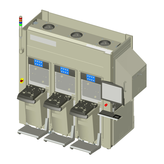
Brooks Automation 2. Overview Part Number: 606712 Rev. A General Usage Overview General Usage Overview The MARATHON LEAP AX system is a self-contained atmospheric mini-environment for use as an Equipment Front End Module (EFEM) front-end for process and metrology tools. The system provides a positive-pressure ISO Class 1 mini-environment for atmospheric material handling with a precision robotic system (Wafer Engine) for horizontal material transfer. Figure 2-1: Typical MARATHON LEAP AX Common Platform System Fan/Filter Unit (FFU) Wafer Engine, Track, Aligner (inside mini- environment) MARATHON LEAP Load Port Modules (LPMs) Controller (inside mini-environment) Facilities Panel (inside mini-environment) Access door Figure 2-1, is a SEMI-standard compatible interface system designed for manual, AGV, PGV, or OHV automated loading of carriers that contain wafers or other material waiting for horizontal transfer. It is a self contained and fully integrated atmospheric transfer system with Wafer Engine, aligner, load ports, and controls mounted on an integral frame. -
Page 54: N2 Purge Overview
2. Overview MARATHON LEAP AX General Usage Overview Part Number: 606712 Rev. A The mini-environment supports the Wafer Engine, track, aligner, load ports, electronics, and Fan/Filter Unit, provides a single connection point for all facilities, and provides interface locations for the users process equipment. N2 Purge Overview The MARATHON LEAP AX N2 Purge system is designed to meet SEMI E49 standards. The MARATHON LEAP AX N2 Purge Option can be retrofit in the field and is field serviceable. Copyright © 2023, Brooks Automation, Inc. -
Page 55: Using This Manual
Using this Manual Using this Manual Read the Safety Chapter Failure to review the Safety chapter and follow the safety warnings can result in death or serious injury. All personnel involved with the operation or maintenance of this product must read and understand the information in this safety chapter. Follow all applicable safety codes of the facility as well as national and international safety codes. Know the facility safety procedures, safety equipment, and contact information. Read and understand each procedure before performing it. The MARATHON LEAP AX and MARATHON LEAP N2 Purge systems are intended for use in a industrial environment by trained personnel and should be serviced only by Brooks or Brooks trained representatives. The manuals and related materials are intended for use by trained and experienced technical personnel. The manufacturer accepts no liability for any other use of the equipment or its individual parts and components. This also applies to service and repair work carried out by unauthorized service personnel. All warranties are declared null and void in the event of non-compliance with these instructions. This also applies to parts not directly affected by any unauthorized repair work. If there are any questions regarding this manual or use of this system or to order additional copies of this publication, contact Brooks Automation Service. Copyright © 2023, Brooks Automation, Inc. -
Page 56: Concepts And Terminology
Part Number: 606712 Rev. A Concepts and Terminology The concepts and terminology defined in the section are used throughout this document. Users should read this section first before continuing with the manual. Abbreviation Description Controller Area Network Counterclockwise Clockwise DI Water Deionized water EFEM Equipment Front End Module Emergency Machine Off FIMS Front Opening Interface Mechanical Standard FOSB Front Opening Shipping Boxes FOUP Front Opening Unified Pod Field Replaceable Unit Graphical User Interface Infrared LEAP Leading Edge Application Platform Load Port Overhead Transport Printed Circuit Board Pod Door Opener Safety Data Sheet Technical Support Bulletin Copyright © 2023, Brooks Automation, Inc. -
Page 57: Product Illustration
Brooks Automation 2. Overview Part Number: 606712 Rev. A Product Illustration Product Illustration Front Illustration Copyright © 2023, Brooks Automation, Inc. -
Page 58: Rear Illustration
2. Overview MARATHON LEAP AX Product Illustration Part Number: 606712 Rev. A Rear Illustration Copyright © 2023, Brooks Automation, Inc. -
Page 59: Right Side Illustration
Brooks Automation 2. Overview Part Number: 606712 Rev. A Product Illustration Right Side Illustration Copyright © 2023, Brooks Automation, Inc. -
Page 60: Left Side Illustration
2. Overview MARATHON LEAP AX Product Illustration Part Number: 606712 Rev. A Left Side Illustration Copyright © 2023, Brooks Automation, Inc. -
Page 61: Marathon Leap Load Ports
Brooks Automation 2. Overview Part Number: 606712 Rev. A MARATHON LEAP Load Ports MARATHON LEAP Load Ports Load Port Front View Figure 2-2: Front View, Typical LED panel LED cover FIMS door Shuttle/FOUP advance Service cart Main board cover Copyright © 2023, Brooks Automation, Inc. -
Page 62: Load Port Rear View
2. Overview MARATHON LEAP AX MARATHON LEAP Load Ports Part Number: 606712 Rev. A Load Port Rear View Figure 2-3: Rear View, Typical Welded frame FIMS door cover Door drive FIMS door Lower mount Copyright © 2023, Brooks Automation, Inc. -
Page 63: Shuttle
Brooks Automation 2. Overview Part Number: 606712 Rev. A MARATHON LEAP Load Ports Shuttle The shuttle module is a component of the MARATHON LEAP AX that is required to position the FOUP on the load port for processing by the Host Tool and AMHS system. The shuttle module uses kinematic pins to position the carrier for AMHS transfers, positions the FOUP in an orientation for opening the FOUP door, and positions the kinematic pins for wafer handling by a front end robot. The shuttle module also latches and secures the carrier to prevent removal of the carrier by operators with adequate holding force to allow door opening, resisting operator applied forces, and a means of reading and/or writing to the carrier RFID tag. Figure 2-4: Typical Shuttle Copyright © 2023, Brooks Automation, Inc. - Page 64 2. Overview MARATHON LEAP AX MARATHON LEAP Load Ports Part Number: 606712 Rev. A Manual Load/Unload Push Button The shuttle plate features one push button switch to load and unload the FOUP. This push button is end-user configured. The push button is normally left in its default configuration. Figure 2-5: Typical Shuttle - Manual Load/Unload Button Copyright © 2023, Brooks Automation, Inc.
- Page 65 Brooks Automation 2. Overview Part Number: 606712 Rev. A MARATHON LEAP Load Ports Sensors The MARATHON LEAP Load Port software uses two sensing systems, FOUP Placement and FOUP Presence, to ensure that the shuttle does not operate unless the FOUP is properly positioned. When the FOUP is placed on the kinematic pins of the shuttle, the presence sensor detects the presence of the FOUP and the placement sensors detect if the FOUP has been properly placed. Copyright © 2023, Brooks Automation, Inc.
-
Page 66: Fims Door
2. Overview MARATHON LEAP AX MARATHON LEAP Load Ports Part Number: 606712 Rev. A FIMS Door The MARATHON LEAP Load Port Front-Opening Interface Mechanical Standard (FIMS) door is used to open a 25-wafer FOUP. Two latch keys located on the FIMS door rotate horizontally to unlock the FOUP door. After the port door latch keys secure the FOUP door, it backs away from the FOUP, and lowers until the FOUP opening is cleared. Once the port door is lowered, the wafers are accessible for processing. Figure 2-6: Typical FIMS Door - Front Registration Pin Latch Keys FOUP-at-Port Sensors Copyright © 2023, Brooks Automation, Inc. - Page 67 2. Overview Part Number: 606712 Rev. A MARATHON LEAP Load Ports Sensors SMART Door Sensing The smart door addresses FOUP variability. Two FOUP-at-Port sensors locate the position of the FOUP door at the docked position. NOTE: The FAP1/FAP2 SD (Smart Door) Dock Calibrated Position is only used if door detect is enabled. Disabling the smart door can result in the door crashing, which can cause wafer damage. As of version 2.5.4.40, the smart door is enabled by default. FAP sensor calibration must be performed at install because the sensors are adjusted to SEMI spec. If the F OUPs are out of spec, the sensors may trigger outside of the +/- window, which results in an error. Ground Path to FOUP Door The MARATHON LEAP AX provides a path to ground from the FOUP door through the port door latch keys, when the FOUP door is removed from the FOUP. Configurable Latch Key Over-Rotation The MARATHON LEAP Load Port rotates the latch key from the locked position at 90 degrees (FOUP Door locked position) to the unlocked position of 0 degrees. The MARATHON LEAP AX can be configured for over-rotation at the 90 degree position to 1,2, or 3 degrees over-rotate through the GUI Interface. The factory default setting for over-rotate is 2 degrees. Copyright © 2023, Brooks Automation, Inc.
-
Page 68: Wafer Mapper (Optional)
2. Overview MARATHON LEAP AX MARATHON LEAP Load Ports Part Number: 606712 Rev. A Wafer Mapper (Optional) Figure 2-7: Typical Wafer Mapper Mapper Arms The MARATHON LEAP Load Port has a break-the-beam wafer mapping system attached to the FIMS door that consists of two arms. The wafer mapper operates during the vertical movement of the port door to map wafers and detect cross-slotting and double wafer slotting. Wafer Map Motors (Part of Wafer Mapper) There are two wafer map motors, one controlling each of the two Wafer Mapping arms. Copyright © 2023, Brooks Automation, Inc. -
Page 69: Door Drive Mechanism
Door Drive Mechanism Fan Assembly The fan assembly is located on the lower mount of the door drive subassembly. It provides a continuous flow of air away from the door drive mechanism. N2 Purge The system provides inert gas encapsulation of products sensitive to the environmental composition by controlling the composition of the environment inside the FOUP. Connection Requirement/Specification Connector Type 60-100 psi 1/2" VCR 70-100 psi 8 mm push-in 110-230 AC IEC-320 Power 24VDC AMP Series-1 4-Positions CPC Connect the facility N2 Exhaust line to the N2 Exhaust 8 mm push-in connection at this location on the EFEM. User Interface Figure 2-8: Typical LED Panel with Cover Copyright © 2023, Brooks Automation, Inc. -
Page 70: Plumbing Architecture
2. Overview MARATHON LEAP AX Plumbing Architecture Part Number: 606712 Rev. A Carrier Door Check and Warning Display The corresponding LED lights are ON if a sensor detects one of the following events: A carrier (FOUP or FOSB) door comes off while on the load port. An error signal is sent to host if this occurs outside the normal load/unload sequence. A carrier door on the FOUP/FOSB that is not in the proper position per Semi Standard and is protruding outside the Semi compliant zone. Plumbing Architecture Location of the facility panel, LOTO, Regulator, and Valve at the back of the MARATHON LEAP AX. Figure 2-9: N2 Facility Panel, LOTO, Regulator, and Valve; Typical Copyright © 2023, Brooks Automation, Inc. -
Page 71: N2 Flow
Brooks Automation 2. Overview Part Number: 606712 Rev. A N2 Flow N2 Flow Flow Rate Specs The total flow rate is programmable to a maximum of 180 SLM per load port. The maximum flow rate for Front Purge Port should be 60 SLM and a maximum for the rear port pair 120 SLM (a total of 720 SLM for system). Incoming flow is monitored via Insight. Incoming gas is filtered at the tool. CDA supply is set to be around 70-100 psi. Copyright © 2023, Brooks Automation, Inc. -
Page 72: Specifications And Site Requirements
2 Bay: 1402.98 mm (55.23 in) Width 3 Bay: 1907.90 mm (75.11 in) 4 Bay: 2418.8 mm (95.23 in) Depth 1363 mm Height 1864 mm Site Requirements Space Requirements Table 3-2: 300 mm MARATHON LEAP AX System Space Requirements, Typical Estimated Model Weight with Optional Storage Weight 2 Wide 484 kg (1067 lb) 550 kg (1213 lb) 3 Wide 600 kg (1323 lb) 668 kg (1473 lb) 4 Wide 716 kg (1579 lb) ... -
Page 73: Environmental Requirements
3. Specifications and Site Requirements Part Number: 606712 Rev. A Site Requirements Figure 3-1: Typical Working Clearance Environmental Requirements Table 3-3: Environmental Specifications Specification Value Temperature- 10° C to 30° C (50° F to 86° F) Operating: -25° C to 55° C (-13° F to 131° F), up to 65° C (149° F) for 24 hrs. max Shipping: -25° C to 55° C (-13° F to 131° F), up to 65° C (149° F) for 24 hrs. max Storage: Humidity 5% to 80% (Relative, non-condensing) Standard lighting provided in the cleanroom environment where the system is installed is Lighting sufficient for proper operation. Maintenance may require additional light. Copyright © 2023, Brooks Automation, Inc. -
Page 74: Power Specifications
Overvoltage Category II The MARATHON LEAP AX PDU is supplied with 10,000 AIC circuit breakers. SCCR 10,000A The facility is responsible for the main disconnect device between the MARATHON LEAP AX system and the facility’s power source and for ensuring that it complies with the correct electric codes. Service to the MARATHON LEAP AX system must have the appropriate fuse or circuit breaker rating. Before connecting or disconnecting main power to the MARATHON LEAP AX system, ensure that all MARATHON LEAP AX system and related equipment circuit breakers are in the OFF position. Damage to internal components may result if circuit breakers are left in the ON position. The facility available fault current must be less than the stated SCCR (10,000A). Power Cable The PDU, c arries power to the modules of the MARATHON LEAP AX system (controller, Wafer Engine, aligner, etc.) via the supplied power cables. The user must provide the power cable carrying facilities power to the MARATHON LEAP AX system’s PDU. The pin-out for the PDU’s 200 - 240 VAC cable is provided in Table 3-4. Table 3-4: AC Power Cable Pin ID 1 Phase N/L2 L/L1 Copyright © 2023, Brooks Automation, Inc. -
Page 75: Facilities Specifications
Connector on PDU Connector Required for Power Cable Hubbell 2325 (HBL2325) Hubbell 2323 (HBL2323) Type L6-20R Twist locking body connector Type L6-20P Flange inlet AC connector 250 VAC, 20A, single Phase, female 250 VAC, 20A, single Phase, male Facilities Specifications Vacuum: 80 kPa @ ≥ 6 l/m (100 cc/sec) 85-105 psi 720 SLM 1/2" VCR Male Inlet CDA: 70-100 psi 4.0 cfm at 90 psi 8 mm One Touch Fitting NOTE: These facility requirements are to support a Marathon with a max configuration of (4) N2 load ports with 180SLMs per load port. Copyright © 2023, Brooks Automation, Inc. -
Page 76: Network Interface Connections
Part Number: 606712 Rev. A Network Interface Connections Network: Ethernet, 10/100 Mbit/sec Ethernet Communications The MARATHON LEAP AX system uses the Ethernet communications protocol to connect a number of different devices to a factory controller, using a single communications cable. Standard Ethernet IP Address and Serial Gateway Port Addresses lists the default IP addresses of host-controlled components in the MARATHON LEAP AX. For systems where the Wafer Engine controller is in control of the device, those addresses cannot be externally controlled by the host. See the system selection guide for guidance. The load port settings reflect the default load port and load port carrier ID setup. Port numbers are reserved. Alternate uses of ports should be given other port numbers. Figure 3-2: TCP Port Format The Ethernet cables are standard network cable (UTP-CAT5e) with an 8-pin RJ-45 connector that connect to the MARATHON LEAP AX system Facilities Panel. Refer to Figure 6-4 on page 122 for the connection location. Copyright © 2023, Brooks Automation, Inc. -
Page 77: Wafer Engine Specifications
Vacuum grip End effector type Passive edge contact Active edge grip Software interface Brooks API Weight Approximately 30 kg System Specifications Table 3-7: System Specifications Specification 200-240VAC, 50/60Hz, single phase, (L1,L2,PE) System full load current 15A Electrical Constant load range 5 - 14A depending on configuration Overvoltage Category II The PDU is supplied with 10,000 AIC circuit breakers SCCR 10,000A Short Circuit Current Rating 10,000 Amps (SCCR) Sound pressure level Less than 70 dBA Weight See Table 3-2 on page 72. Operating temperature 10 to 40° C. Operating humidity 10 to 75% non-condensing Environmental Storage temperature -10 to +55°C. Storage humidity 5 to 90% non-condensing Copyright © 2023, Brooks Automation, Inc. -
Page 78: Ec-6 Controller
3. Specifications and Site Requirements MARATHON LEAP AX EC-6 Controller Part Number: 606712 Rev. A EC-6 Controller The Equipment Controller (EC) is located inside the EFEM, mounted on the lower panel below the Wafer Engine mounting plate. The Brooks API controls the embedded Equipment Controller Software (EC) as well as the interface software.The EC Service GUI is accessed via a user interface called BAI.InSight. BAI.InSight allows control of the individual components and all setup, maintenance, and diagnostic-related activities. There are no user serviceable parts inside the Equipment Controller. In case of malfunction, replace the EC. Contact Brooks Automation for a replacement. Specifications The EC-6 weighs 3.8 kg (8.25 lbs). The EC-6 is a Field Replaceable Unit (FRU). Copyright © 2023, Brooks Automation, Inc. -
Page 79: Installation
Brooks Automation 4. Installation Part Number: 606712 Rev. A 4. Installation For complete installation procedure, see the latest version of the Installation Procedure (357629). Copyright © 2023, Brooks Automation, Inc. -
Page 80: 5. Alignment And Teaching
Read the Safety Chapter Failure to review the Safety chapter and follow the safety warnings can result in death or serious injury. All personnel involved with the operation or maintenance of this product must read and understand the information in this safety chapter. Follow all applicable safety codes of the facility as well as national and international safety codes. Know the facility safety procedures, safety equipment, and contact information. Read and understand each procedure before performing it. MARATHON LEAP AX System Alignment and Teaching The components of the system were aligned at the factory prior to shipment. However, even a small misalignment can interfere with proper system operation. Thus, prior to use, the components within the Brooks Automation MARATHON LEAP AX must be aligned to each other to prevent misplacement of material or collision of the Wafer Engine with other parts of the system. Also, the MARATHON LEAP AX must be aligned with the system that it will be operating in to prevent misplacement of material or collision of any material handling components. Brooks Automation recommends performing the alignment procedures under the following circumstances: A complete alignment when the MARATHON LEAP AX is first set up at the user’s site. A complete check when performing routine maintenance. Copyright © 2023, Brooks Automation, Inc. -
Page 81: Required Tools And Test Equipment
Performing the alignment procedure requires the following tools and materials: The parameter sheet for all Wafer Engine stations from the system Acceptance Test (AT) shipped with the system A portable computer running control software, or a keyboard, mouse, and monitor connected to the controller MicroTool dummy wafers or test material of the type and size for which the system is being set up The user manual for the controller The user manual(s) for each device that interfaces with the MARATHON LEAP AX Alignment Process Alignment consists of adjusting the mechanical components of the system using a c omputer to operate the MARATHON LEAP AX's components. The MARATHON LEAP AX must be installed and attached to the process tool or the customer’s system. Proper alignment ensures that the Wafer Engine or material being transferred does not contact the surfaces of the MARATHON LEAP AX and no sliding motions occur between material and support surfaces. Tip Hazard Tip hazard exists when the Marathon system is not attached to the process tool which may cause death or serious injury. Be away of tip hazards and take appropriate precautions when aligning the components of the MARATHON LEAP AX. Wear Personal Protection Equipment such as steel toe shoes and eye protection. Copyright © 2023, Brooks Automation, Inc. - Page 82 Part Number: 606712 Rev. A Automatic Movement The possibility of automatic movement exists with the MARATHON LEAP AX components. These components do not have obstruction sensors and may cause death or personal injury. The Wafer Engine, track, aligner, LPMs, and FFU fans all have the possibility of automatic movement: The user is responsible for any damage to the MARATHON LEAP AX system. Do NOT perform a “Home” operation of any of the material handling modules within the MARATHON LEAP AX during the alignment procedure unless specifically directed to do so. It is important to perform the alignment in the sequence shown in this section for maximum operating performance of the MARATHON LEAP AX. Step Action Read and understand the "Safety" chapter. Become familiar with the Wafer Engine and all attached subsystems. Ensure that the MARATHON LEAP AX, the process tool, and all associated components are at room temperature. Power up and initialize the MARATHON LEAP AX and all devices that interface with the MARATHON LEAP AX. The system must be in the following state: All process tool load lock vacuum chambers must be at atmosphere. All process tool load lock atmospheric doors must be open. Follow the alignment procedures in this section in the order presented. Refer to the user manual for the affected component as required. Record the station coordinates for the Wafer Engine in the appropriate worksheet. Copyright © 2023, Brooks Automation, Inc.
-
Page 83: Adjust The Load Port Modules (Lpms)
Step Action Place a MicroTool electronic level on the station bottom surface to record Pitch and Roll. Make sure that the wafer level orientation relative to the Wafer Engine remains consistent as it was with the system enclosure leveling. If the surface level is greater than ± 0.10°, recofirm the levelness of the entire station. Place a MicroTool electronic wafer level on the handoff shelf to record Pitch and Roll. Make sure the wafer level orientation relative to the Wafer Engine remains consistent as it was with the system enclosure leveling. If the surface is level within ± 0.10° but the shelf is greater than ± 0.10°, relevel the handoff shelf. NOTE: In some cases the station(s) cannot be adjusted. If so make a note and continue leveling the end effectors. Copyright © 2023, Brooks Automation, Inc. -
Page 84: Adjust The End Effector(S)
Adjust the End Effector(s) Do not adjust the end effectors until the system enclosure has been fully leveled as well as the critical handoff station(s). Perform leveling of the end effector(s) at the most critical station such as load locks or custom modules. It is recommended to level at the tightest station if possible. In many cases, the critical station may be very space limited and load port stations can then be used. Check the level of the end effector(s) at all stations. If necessary, adjust the Pitch and Roll values to within 0.06 degrees difference relative to all stations. NOTE: If the Pitch and Roll values of the critical station(s) differs more than 0.1 degrees from the load port stations, it is recommended to adjust the load port station leveling to reduce the difference (while, if applicable, keeping the load port Pitch and Roll within the specifications for OHT handoff). Mount Tie-Down Brackets The MARATHON LEAP AX has 4 tie-down points that provide anchoring to eliminate movement and provide seismic anchoring for earthquake protection per SEMI S2. Two tie-down points are located on each end. NOTE: Seismic hold-down brackets for facilities requiring earthquake protection are the responsibility of the user. The shipping brackets supplied with the MARATHON LEAP AX are for shipping only. The user must supply their own brackets and hardware for facility tie-down or seismic tie-down. Copyright © 2023, Brooks Automation, Inc. - Page 85 Brooks Automation 5. Alignment and Teaching Part Number: 606712 Rev. A Alignment Process Figure 5-1: Seismic Hold-Down Bracket Location Step Action Install Grade 5 or better M12 mounting hardware (not supplied) at each of the (4) tie-down points to secure the user supplied brackets. See Figure 5-1. Secure the user supplied bracket to the facility’s floor using Grade 5 or better mounting hardware (including flat washers and split washers) and tighten to a torque of 11 newton meters (100 inch pounds). Copyright © 2023, Brooks Automation, Inc.
-
Page 86: Final Checkout
Once all material handling devices in the MARATHON LEAP AX have been set up for all transfers, verify proper transfer of material to and from all stations within the system. NOTE: This procedure must be performed during initial setup and at any time that any material handling device is damaged, removed and replaced, or changed. Personal Protective Equipment Breaking material may produce flying shards which may cause personal injury. Wear protective eye equipment at all times when using wafers or any other fragile material. Procedure Category Type 2 Procedure: Equipment is energized and all energized circuits are covered or insulated. Work is performed remotely using the service computer. Required Tools and Test Equipment MicroTool dummy wafer(s) or test wafer(s) of the appropriate size FOUP(s) of the appropriate size Checkout Procedure Step Action Starting at a slow speed, PICK the material from one station and PLACE it into another station while observing the system to verify proper operation. Repeat Step 1 to transfer the material back to its original location. Repeat Step 1 and Step 2 for each end effector for each station. Copyright © 2023, Brooks Automation, Inc. -
Page 87: End Effector Leveling-Validation
Part Number: 606712 Rev. A End Effector Leveling-Validation End Effector Leveling-Validation NOTE: Perform leveling of the end effectors at most important station such as load locks or custom modules. It is recommended to utilize leveling at the tightest station if possible. In many cases, leveling end effector at most important stations may be very space limited and load port stations with most similar orientation as load lock or custom station can then be used. Aligner Leveling-Validation The aligner is leveled relative to the end effector(s). Do not adjust the aligner until the end effector(s) have been adjusted. Please follow the lockout/tagout procedures listed in "System Lockout/Tagout Procedure" on page 117 before starting the leveling process. Step Action Adjust the CCD mount by placing the height adjust piece (shown in orange in Figure 5-2) to increase the clearance. Extend the Wafer Engine arm to the hand-off position of the aligner above the chuck. Place a MicroTool electronic wafer level on the Wafer Engine end effector and record the Pitch and Roll values from either the tablet or the PC MicroTool software. Ensure that the wafer level orientation towards the Wafer Engine is the same as when leveling the end effector(s). Copyright © 2023, Brooks Automation, Inc. - Page 88 5. Alignment and Teaching MARATHON LEAP AX Aligner Leveling-Validation Part Number: 606712 Rev. A Step Action Place electronic wafer level onto the chuck of the aligner and center the wafer level, aligning the wafer with the alignment marks on the chuck. Ensure that the wafer level orientation relative to the Wafer Engine remains consistent as it was with the system enclosure leveling. Figure 5-2: Typical Aligner with Sample Wafer Attach the electronic level’s strain relief clip nearby so that there is no interference with the electronic wafer level. Verify that the levelness is within 0 ±0.02° of the Pitch and Roll values of the end effector that is extended at the aligner position. Copyright © 2023, Brooks Automation, Inc.
- Page 89 5. Alignment and Teaching Part Number: 606712 Rev. A Aligner Leveling-Validation Step Action If it is not within the specifications, adjust the kinematic mounts: a. Loosen the mounting screws. b. Adjust the kinematic mounts to obtain 0 ±0.02° of the Pitch and Roll values relative to the end effector. c. Secure the mounting screws. d. Verify that the Pitch and Roll values have not changed. e. Remove the electronic wafer level. Copyright © 2023, Brooks Automation, Inc.
-
Page 90: Teaching Stations Overview
Put Position 0.000 * Theta 90 +/-3 A/R 270 +/-3 A/R Slot1 Z EE Top Dive -4.250 0.000 EE Bottom Dive 1.000 0.000 -Offset (Z) 3.150 3.000 +Offset (Z) 3.000 3.000 Pitch 10.000 10.000 Teach Slot Total Slots Handoff Type One-step One-step, Fast swap Extend/Retract Both Both Fast Type of Automatic Automatic Trajectory Copyright © 2023, Brooks Automation, Inc. -
Page 91: Required Tools
PortA, PortB, PortC (LPMs) PortU EE1 Full Speed 75000 Jerk EE2 Full Speed 75000 Jerk * A dummy PortU station should be taught for testing at 319.4 mm from rear plane of EFEM (not bumpout), and then reset to 0 afterwards. Required Tools The following materials must be prepared before proceeding. Alignment pucks are specific to the end effector being used. Figure 5-3: Examples of Alignment Plate (Left) and Alignment Puck (Right) For specific part numbers associated with your system, please contact TechSupport@brooks.com. Preparation Step Action All wafers and FOUPs/cassettes must be removed from stations before starting to teach. Stations to be taught must be ready for Wafer Engine access (doors open and shuttles docked if present). Copyright © 2023, Brooks Automation, Inc. -
Page 92: Teaching Load Port Hand Offs
Teaching the Load Port Step Action On the Insight GUI, select the Teach panel (center section of the GUI). a. Select the desired end effector to be taught in the Teach Host drop-down menu. b. Select the desired load port to be taught in the Teach Station drop-down menu. c. Select the desired teach carrier type. d. Select the desired teach substrate type. e. Select Slot 1. f. Set Teach Slot to Slot 1. g. Click MvReadyPut. The Wafer Engine will move to the currently taught coordinated for that station/end effector position without extending the end effector. h. Jog the Z -axis to 50 mm for end effector 1 and 35 mm for end effector 2. Open the service door. This disables all axes. Perform the Lockout/Tagout procedure on the Wafer Engine. See "Wafer Engine Lockout/Tagout Pro- cedure" on page 119. Copyright © 2023, Brooks Automation, Inc. - Page 93 NOTE: For a passive end effector, line up the top of the end effector to the top of the puck. For 300 mm passive edge contact, line up the top of the end effector to the top of the puck. Copyright © 2023, Brooks Automation, Inc.
- Page 94 300mm teach position. AM3010 -24.15mm from the 300mm EE read position. +3.62mm from the 300mm EE Z read position. This number is a starting point and has to be verified for the cassette used. 200 mm cassette brands have different tilt angles that affect the Z wafer position. AM3006 -49.45mm from the 300mm EE reach position. +3.62mm from the 300mm EE Z read position. This number is a starting point and has to be verified for the cassette used. 200 mm cassette brands have different tilt angles that affect the Z pick position. Verify that you have the correct end effector and station selected and click the Save button. This will store the coordinates. Move the end effector by hand back in through the load port door Repeat these steps for second end effectors. Close the load port door. After teaching both end effectors to a load port: a. Remove the teach jigs. b. Place a carrier on the load ports. c. Home the load port. Repeat for the additional attached load ports. Remove the Lockout/Tagout. Copyright © 2023, Brooks Automation, Inc.
- Page 95 Brooks Automation 5. Alignment and Teaching Part Number: 606712 Rev. A Teaching Load Port Hand Offs Figure 5-4: Wafer Engine Teach Tab Figure 5-5: Wafer Engine Teach Tab, Read Current Position Copyright © 2023, Brooks Automation, Inc.
-
Page 96: Passive End Effector
5. Alignment and Teaching MARATHON LEAP AX Teaching Load Port Hand Offs Part Number: 606712 Rev. A Passive End Effector Copyright © 2023, Brooks Automation, Inc. -
Page 97: Film Frame End Effector
Brooks Automation 5. Alignment and Teaching Part Number: 606712 Rev. A Teaching Load Port Hand Offs Film Frame End Effector Copyright © 2023, Brooks Automation, Inc. -
Page 98: 300 Mm Passive Edge Contact
5. Alignment and Teaching MARATHON LEAP AX Teaching Load Port Hand Offs Part Number: 606712 Rev. A 300 mm Passive Edge Contact Copyright © 2023, Brooks Automation, Inc. - Page 99 Brooks Automation 5. Alignment and Teaching Part Number: 606712 Rev. A Teaching Load Port Hand Offs Copyright © 2023, Brooks Automation, Inc.
-
Page 100: Teach The Pre-Aligner Station With Fixture
b. On your keyboard, press Ctrl + Print Screen, paste in to MS Paint and save the file to a location for later use. c. Repeat for EE2 (upper). The Commanded Position row and Station Data section(see below) will show the currently stored coordinates for the selected Teach Host/Teach Station combination. Figure 5-6: Wafer Engine Teach tab - Command Position,Teach Station and Teach Host MVReadyGet to position the WE in location for teach by completing Step 3 through Step 13. Open the door. Perform the Lockout/Tagout procedure on the Wafer Engine. See "System Lockout/Tagout Procedure" on page 117. Manually retract the end effectors away from the Pre-Aligner chuck. Place the Teach Puck over the Pre-Aligner chuck. Manually extend the lower end effector to the Teach Puck. Copyright © 2023, Brooks Automation, Inc. - Page 101 Brooks Automation 5. Alignment and Teaching Part Number: 606712 Rev. A Teach the Pre-Aligner Station with Fixture Step Action Use a 3 mm hex wrench to drive the Z-axis up or down as necessary to position the end effector so that the top edge of the end effector is positioned at the Aligner “teach” scribe mark on the fixture. Verify command position of X matches current position. Copyright © 2023, Brooks Automation, Inc.
- Page 102 Step Action Adjust X if needed and re-verify the end effector with the Teach Puck. Figure 5-7: Puck on Aligner Chuck Teach puck with scribe mark Figure 5-8: End Effector with Teach Puck Teach puck without scribe mark Passive Edge Contact EE Teach Adapter NOTE: Teach top surface of EE teach adapter to top of Teach puck. Copyright © 2023, Brooks Automation, Inc.
- Page 103 Brooks Automation 5. Alignment and Teaching Part Number: 606712 Rev. A Teach the Pre-Aligner Station with Fixture Step Action Move the track by hand to get as close to the commanded position for X as possible. Once everything is in the proper position in the Station Editor section of the teach panel, verify that you have the correct end effector and station selected, and that the offset is set to 3.0 mm. Then click Read Current Position and Save. Manually retract EE1. Repeat Step 3 through Step 13 using EE2 (upper). Remove the Lockout/Tagout. Close the door. Enable all axes. Copyright © 2023, Brooks Automation, Inc.
-
Page 104: Operation
Part Number: 606712 Rev. A 6. Operation Overview This chapter provides a review of the MARATHON LEAP AX and general operation instructions for the MARATHON LEAP AX and the major subsystems. The operation of the system is covered for both normal and emergency conditions. This chapter is not a complete reference for developing the software and hardware for MARATHON LEAP AX operation. The user is required to configure the details of operation for their specific application, such as material transfer routing and option configuration. For illustration purposes, the components shown here are the Wafer Engine, track, Wafer Aligner, and Fusion Controller. When using this manual, always refer to the appropriate documentation for the specific components used on your system. Read the Safety Chapter Failure to review the Safety chapter and follow the safety warnings can result in death or serious injury. All personnel involved with the operation or maintenance of this product must read and understand the information in this safety chapter. Follow all applicable safety codes of the facility as well as national and international safety codes. Know the facility safety procedures, safety equipment, and contact information. Read and understand each procedure before performing it. Copyright © 2023, Brooks Automation, Inc. -
Page 105: Theory Of Operation
Brooks Automation 6. Operation Part Number: 606712 Rev. A Theory of Operation Theory of Operation The MARATHON LEAP AX is a self-contained atmospheric mini-environment for use as an Equipment Front End Module (EFEM), front-end for process and metrology tools. The system provides a positive-pressure ISO Class 1 mini environment for atmospheric material handling with a precision robotic system for horizontal material transfer. Wafers, or other materials, are introduced into the MARATHON LEAP AX through Load Port Modules (LPMs). These modules allow up to 25 wafers to be loaded at one time using SEMI standard wafer carriers. The LPMs provide Carrier ID as an option for tracking carrier location within the facility. Wafers may then be passed through the system to the user’s process tool. The mini-environment provides air test ports per I300I (one per door). It is the user’s responsibility to perform any particle measurements. Optional ionizers placed within the airflow reduce/eliminate static charges on the material being transferred within the mini-environment. The mini-environment has SEMI compatible load port interfaces and provides a centralized location for all facilities connections. All material handling components are installed using kinematic mounts that are adjusted at the factory. Copyright © 2023, Brooks Automation, Inc. -
Page 106: Operation Overview
6. Operation MARATHON LEAP AX Theory of Operation Part Number: 606712 Rev. A Operation Overview The following sequence demonstrates the normal operation of the MARATHON LEAP AX. The sequence shown is for a MARATHON LEAP AX with two LPMs, one Wafer Engine without a track, and one aligner connected to a process tool with one load lock. The wafer flow is from one LPM to the process tool load lock and then back to the original LPM. Step Action Load material to be processed into the system: A wafer carrier is placed on one of the LPMs attached to the MARATHON LEAP AX. The host instructs the LPM to open the wafer carrier and map the wafers in the carrier. The LPM provides the wafer map to the host when requested. Pick wafer from the carrier and align: The host instructs the atmospheric Wafer Engine to remove a wafer from the carrier on the LPM and place it on the atmospheric aligner within the MARATHON LEAP AX. Copyright © 2023, Brooks Automation, Inc. - Page 107 6. Operation Part Number: 606712 Rev. A Theory of Operation Step Action Align wafer and place into the process tool: The host instructs the atmospheric aligner to align the wafer and orient the fiducial of the wafer. The host instructs the atmospheric Wafer Engine to pick the wafer from the aligner. The aligner measures the angle and eccentricity of the wafer and adjusts the Wafer Engine's end effector’s position during the pick to center the wafer on the end effector. The host instructs the Wafer Engine to place the centered and oriented wafer into the user’s process tool. Pick next wafer from carrier and align. Place processed wafer into the carrier. The host instructs the atmospheric Wafer Engine to remove the next wafer from the carrier on the LPM and place it on the atmospheric aligner within the MARATHON LEAP AX system. The host instructs the Wafer Engine to remove the processed wafer from the user’s process module and place it into the carrier on the LPM. The cycle (Step 3 and Step 4) repeats until all wafers in the carrier have been processed. Once all of the wafers within the wafer carrier have been processed, the wafer. The carrier is removed and replaced with the next carrier to be processed. Copyright © 2023, Brooks Automation, Inc.
-
Page 108: Block Diagrams
Part Number: 606712 Rev. A Block Diagrams A block diagram specific to the Marathon LEAP AX shipped to the customer will be provided as a separate document. Station Naming System Control software uses a station naming system for identifying specific locations within the MARATHON LEAP AX and the system it is interfacing with, as shown in Figure 6-1. The MARATHON LEAP AX uses a true Cartesian coordinate system where each station is given a name and identified by its X, Y, and Z position. By identifying the stations in this manner, it is only necessary to provide the controller with the station name instead of the complete coordinate set each time a station related command is issued. Multiple station names may be given to a single physical location. Figure 6-1: Station Assignments - MARATHON LEAP AX 2 Wafer Engine Aligner Load Port Modules (LPM) Brooks Automation configures the stations on the MARATHON LEAP AX as shown unless different station assignments are specifically requested. All references to setting stations in this manual will reflect the standard Brooks EFEM station assignments. Copyright © 2023, Brooks Automation, Inc. -
Page 109: Frame Of Reference
Frame of Reference Before setting stations or using the MARATHON LEAP AX, it is important to understand the frame of reference used within the system. Material is transferred to specific locations, or stations, within the system by the Wafer Engine. Each location is defined by its X, Y, and Z position within the system’s frame of reference. Station definition is the process of defining each of these locations, which are then stored in the controller’s memory for future reference. It is important to note that the system’s frame of reference is defined by the controller, as described below, and that each station is defined by the X, Y, and Z coordinates, and by other station values. System Frame of Reference The typical frame of reference for the MARATHON LEAP AX is defined by the global Cartesian coordinate system. The top view shown in is a horizontal x-y plane, and each position within this plane is defined using a Cartesian coordinate notation. The third axis in the MARATHON LEAP AX’s frame of reference is the vertical, or Z, axis. When the Wafer Engine is mounted in a fixed location, as shown in , the system’s origin is centered on the Wafer Engine as shown. When the Wafer Engine is mounted on a track, the system’s origin is centered on the Wafer Engine’s position when the track is at its Home location, as shown in Figure 6-2. Figure 6-2: Global Cartesian Frame of Reference - Wafer Engine on Track Copyright © 2023, Brooks Automation, Inc. -
Page 110: Wafer Engine Frame Of Reference
6. Operation MARATHON LEAP AX Frame of Reference Part Number: 606712 Rev. A Wafer Engine Frame of Reference The typical cylindrical frame of reference for the ATR Wafer Engine is defined by the Wafer Engine’s coordinate system regardless of how the Wafer Engine is mounted. Looking at the top view of the system, the Wafer Engine’s rotational, or T (theta), position value increases from 0° at the home position to 360° in a counter-clockwise direction. The Wafer Engine’s radial, or R, axis is measured from the center-line of the Wafer Engine radially outward to the material center location on the end effector in millimeters. The Wafer Engine’s vertical, or Z, axis is measured from the Wafer Engine’s vertical home position in millimeters. The Wafer Engine’s optional wrist, or W, axes increase from 0° at the home position to 180° in a counter-clockwise direction and 0° to -180° in a clockwise direction. The optional track, or S, axis, is measured from the track’s home position in millimeters. In Wafer Engine systems, the track is referred to as the X-axis. Copyright © 2023, Brooks Automation, Inc. -
Page 111: Start-Up
NOTE: All switch settings, communications connections, power connections, and facilities connections should be made before power is applied. This section describes the recommended procedure for powering up the Brooks Automation MARATHON LEAP AX under normal circumstances. Step Action Verify that all of the installation procedures previously outlined have been completed. Ensure that all switch settings are set according to the instructions. Turn on the PDU starting with CB1, then CB2, CB3, and finally CB4: The FFU Display turns on. The interior service lights turn on. Turn on all load ports. Turn on the Wafer Engine automation controller: Refer to the Wafer Engine user manual for correct initialization sequence. For Wafer Engine systems, refer to the Wafer Engine in the Wafer Engine in JCP EFEM User Manual (232460). If the initialization sequence executes without error, then all the components are communicating successfully. Ensure that all components are properly referenced (home the Wafer Engine, home the aligner, initialize the load ports, set FFU to auto mode, etc.). Normal operation of the Brooks Automation MARATHON LEAP AX is controlled by the user’s host controller. Normal operation would typically proceed as follows: Copyright © 2023, Brooks Automation, Inc. -
Page 112: Safe Shutdown
Part Number: 606712 Rev. A Step Action Power up the MARATHON LEAP AX as previously described. Power up the user’s host controller as directed. Once all systems are up and running properly, proceed as directed by the user's host controller. Safe Shutdown The following shutdown procedure is used to remove power from the MARATHON LEAP AX system in an orderly manner and place the components within the system in safe conditions. This procedure is used to prepare the system for repair, removal, or maintenance. NOTE: When the host controller is to be shut down, the MARATHON LEAP AX system should be shut down first. The shutdown procedure is used in the normal shutdown of the MARATHON LEAP AX system. This procedure completely removes the power source and all other facilities to the system and provides guidelines for lockout/tagout. This procedure is NOT the same as an EMO circuit or other safety interlock. Step Action All material transfers should be completed (move all material to the appropriate LPMs). Command all modules (robot, aligner, LPM, etc.) to a known safe position (e.g., Home). Ensure that the appropriate software is shutdown properly. Turn off and relieve all pressure from process supply lines to the system (e.g., vacuum) compressed air if applicable. Shut down the robot controller. Copyright © 2023, Brooks Automation, Inc. - Page 113 NOTE: The remote ON/OFF switch is located above the EC6 box on the right hand side. Remote ON/OFF Main Switch Turn off power at the PDU in sequence starting with CB4, CB3, CB2, a nd then the main power CB1. Remove the power cable from the source and disconnect it from the system. If moving the system, disconnect the communication cables and pneumatic tubes to the system and to the Facility Panel. NOTE: The vacuum line may or may not go through the Facility Panel. Secure the system using the lockout/tagout procedures defined by the facility. The system's main power circuit breaker CB1 includes a padlock bar to be used as a lockout/tagout device for the system. F ollow local lockout/tagout procedures. If no such procedures exist, follow the procedure for Lockout/Tagout in OSHA Standard 29CFR 1910.147. Copyright © 2023, Brooks Automation, Inc.
- Page 114 Part Number: 606712 Rev. A Step Action If applicable, secure the compressed air supply line using tagout procedures defined by the facility. These procedures may include an isolating device to prevent the supply lines from being connected into the facilities supply, along with information about the purpose of the tagout and the person responsible. If no such procedures exist, follow the procedure for Lockout/Tagout in OSHA Standard 29CFR 1910.147. NOTE: This procedure only shuts down facilities to the system and its subsystems. Any user equipment will remain powered up. Verify that the power has been successfully shut down by testing the AC outlets on the PDU using a volt meter. Copyright © 2023, Brooks Automation, Inc.
-
Page 115: Safety Interlocks
Safety Interlocks Safety Interlocks The MARATHON LEAP AX is provided with safety interlocks to ensure the safety of the operators and service personnel. See "Interlocks" on page 28. Read the Safety Chapter Failure to review the Safety chapter and follow the safety warnings can result in death or serious injury. All personnel involved with the operation or maintenance of this product must read and understand the information in this safety chapter. Follow all applicable safety codes of the facility as well as national and international safety codes. Know the facility safety procedures, safety equipment, and contact information. Read and understand each procedure before performing it. Automatic Movement The possibility of automatic movement exists with MARATHON LEAP AX components. These components do not have obstruction sensors and may cause death or personal injury. The Wafer Engine, track, aligner, LPMs, and FFU fans all have the possibility of automatic movement: The user is responsible for any damage to the MARATHON LEAP AX system. Copyright © 2023, Brooks Automation, Inc. -
Page 116: Door Interlock Circuit
6. Operation MARATHON LEAP AX Safety Interlocks Part Number: 606712 Rev. A Door Interlock Circuit Access to the MARATHON LEAP AX mini-environment is through the tool secured side doors. These doors contain an interlock switch that when opened will stop all automation within the MARATHON LEAP AX and if connected may also stop the process system. Emergency Off (EMO) Circuit The optional EMO button(s) supplied with the MARATHON LEAP AX is provided to allow the user to conveniently expand the tool EMO system to the front of the EFEM. A pass through connection for the user's EMO circuit is provided at the facilities panel through a male M12 connector. T he action caused by pressing the EMO button is determined by the user. Correct implementation should be made according to SEMI-S2. The Wafer Engine controller may contain an Uninterruptable Power Supply (UPS) that is used to provide a con- trolled shutdown of the Wafer Engine and of the controller in the event of power loss. Copyright © 2023, Brooks Automation, Inc. -
Page 117: System Lockout/Tagout Procedure
System Lockout/Tagout Procedure Lockout / Tagout Working with energized equipment may cause sudden movement or electrical shock and may result in death or serious injury. All energy must be removed from the equipment per the host tool’s Lockout/Tagout procedure before servicing. The host must provide isolation devices for electrical and fluid (vacuum) isolation. Isolation devices provided by the host must be readily accessible, lockable only in the isolated position, and located so that the person actuating or inspecting the energy isolating devices is not exposed to serious risks of tripping or falling or of coming in contact with energized electrical parts, moving machinery, surfaces or objects operating at high temperatures, or other hazardous equipment. If local procedures are not available, follow the procedure for Lockout/Tagout in OSHA Standard 29CFR 1910.147. Step Action Notify the affected personnel that a Lockout/Tagout is required. Complete safe shutdown of the MARATHON LEAP AX per process in "Safe Shutdown" on page 112. Place the CB1 in safe condition and the circuit breaker is safe when green appears in window. Window Copyright © 2023, Brooks Automation, Inc. - Page 118 6. Operation MARATHON LEAP AX System Lockout/Tagout Procedure Part Number: 606712 Rev. A Step Action Apply lockout/tagout to the circuit breaker CB1 (MFR PN: Eaton Z-IS/SPE-1TE). Use a volt meter to electrically verify that the MARATHON LEAP AX is de-energized. Complete the necessary maintenance or work to the tool. Inspect the work area to ensure that non-essential items have been removed and that components are intact and capable of operating properly. Check the area around the equipment to ensure that all employees have been safety positioned or removed. Remove only the locks and tags that have been attached. Notify affected employees that locks and tags have been removed immediately after removing locks and tags and before starting equipment. Copyright © 2023, Brooks Automation, Inc.
-
Page 119: Remove System Lockout/Tagout
Part Number: 606712 Rev. A Wafer Engine Lockout/Tagout Procedure Remove System Lockout/Tagout Step Action Inspect the work area to ensure that non-essential items have been removed and that components are intact and capable of operating properly. Check the area around the equipment to ensure that all employees are safety positioned. Remove only the locks and tags that have been attached. Notify employees that locks and tags have been removed immediately and before starting the equipment. Wafer Engine Lockout/Tagout Procedure Step Action Notify the affected personnel that a Lockout/Tagout is required. Complete safe shutdown p er the process in "Wafer Engine Lockout/Tagout Procedure" on page 119 (do not place Lockout/Tagout on the PDU). At the Lockout/Tagout unit (BAI PN: 232479), flip the switch to disable the Wafer Engine motor power. Place the padlock on the Lockout/Tagout switch in the OFF position. Copyright © 2023, Brooks Automation, Inc. -
Page 120: Remove Wafer Engine Lockout/Tagout
Fan Filter Unit (FFU) Part Number: 606712 Rev. A Remove Wafer Engine Lockout/Tagout Step Action Inspect the work area to ensure that non-essential items have been removed and that components are intact and capable of operating properly. Check the area around the equipment to ensure that all employees are safety positioned. Remove only the locks and tags that have been attached. Notify employees that locks and tags have been removed immediately and before starting the equipment. Fan Filter Unit (FFU) The MARATHON LEAP AX Fan Filter Unit (FFU) provides airflow and filtering to maintain an ISO Class 1 or better material handling environment within the MARATHON LEAP AX while maintaining positive internal pressure. Figure 6-3: Typical Fan/Filter Unit Control PCBAs Copyright © 2023, Brooks Automation, Inc. -
Page 121: Description
Fan Filter Unit (FFU) Description The MARATHON LEAP AX FFU is equipped with an active differential air pressure that provides set-point monitoring. The FFU operates between 48VDC. Communications is through Ethernet to the host controller. A ll features may be set and monitored via Ethernet. The pressure set point and alarms are factory set to meet SEMATECH best practices and ISO Class 1 specifications. Changing the pressure set point and EFEM vent louvers may cause the EFEM to be out of spec with ISO Class 1 specifications. FFU Controller The FFU Controller is mounted on the unit. T he controller is designed to automatically control air pressure in the mini-environment. Fan Speed Adjustment Fan speed or mini-environment pressure may be set by the user. The fan is then monitored and driven to maintain the commanded set-point. Set-points and units of measure may be set t hrough the Ethernet communications interface by the host controller. Air Pressure Sensors The FFU uses a differential pressure sensor to monitor air pressure in the mini-environment. Tubing is run from the differential sensor to the mini-environment and to the bay side to monitor the change of pressure from one side of the FFU to the other. The pressure differential between the EFEM and the bay/chase is monitored through the connection to the FFU controller. Operational Interlocks If a fan fails or operates erratically, a signal is sent to the host. If the pressure in the mini-environment deviates from the set point, a signal is sent to the host. Copyright © 2023, Brooks Automation, Inc. -
Page 122: Facilities Panel
6. Operation MARATHON LEAP AX Facilities Panel Part Number: 606712 Rev. A Facilities Panel The facilities panel, shown in Figure 6-4, is the user interface to the Brooks Automation MARATHON LEAP AX. It provides a central location for all facilities, communications, and control connections. The facilities panel is mounted inside the mini-environment on the Service Side on the rear of the system next to the power distribution unit. For some specialized installations, the facilities panel may be mounted in other locations or orientations. Access to an internally mounted facilities panel for user connections can be granted through the cable port below the facilities panel. Mode Selection Switch Facilities Panel Figure 6-4: Typical Facilities Panel Copyright © 2023, Brooks Automation, Inc. -
Page 123: Facilities Panel Functions
6. Operation Part Number: 606712 Rev. A Facilities Panel Facilities Panel Functions The facilities panel provides the following functions: Creates a central connection point for all MARATHON LEAP AX facilities connections. Enables complete access to the controller through an RJ-45 connector for use with IEEE 802.3 style communication (Ethernet). Provides a central location for all user connections (EMO and User Interface). The MARATHON LEAP AX is controlled by a single cable from the host controller using an Ethernet LAN. Different configurations of the system provide different external interfaces. Connections, Controls, and Indicators Figure 6-5: Typical Facilities Panel Facility Vacuum USB for UI Monitor/Keyboard Ethernet (to host) E-Stop Output Copyright © 2023, Brooks Automation, Inc. - Page 124 Part Number: 606712 Rev. A Table 6-1: Facilities Panel Connections Connector Label Description Type Pass through connection to EMO button for user Male M12 Pin EMO circuit Wafer Engine I/O Wafer Engine Parallel I/O DB15 Host Ethernet from Host Controller to controller RJ-45 Ethernet to controller and other MARATHON LEAP Service RJ-45 AX devices Tool Spare Ethernet pass-through for additional devices RJ-45 Video User Interface video connection Female HD-15 Vacuum 8 mm Quick Connect User Interface Keyboard/Mouse USB A Copyright © 2023, Brooks Automation, Inc.
-
Page 125: Power Distribution Unit - Pdu
The PDU is located underneath the X rail, mid section, of the MARATHON LEAP AX. It is easily accessible for service. User connection access is through the cable port located to the side of the facilities panel. Figure 6-6: Typical Power Distribution Unit PDU Functions The PDU provides the following functions: A central connection point for all components internal to the EFEM 48 VDC and soft start power for components requiring DC power A line filter for immunity to external line noise Over-current protection to connected components Safety Controller Interface PCB with diagnostic data available over Ethernet AC and DC power monitoring 48 VDC output contactor for controlling power application to motors Connection point for remote AC ON/OFF switch that is located inside above the EC6 box (right hand service door). Copyright © 2023, Brooks Automation, Inc. - Page 126 6. Operation MARATHON LEAP AX Power Distribution Unit - PDU Part Number: 606712 Rev. A Connections, Controls, and Indicators The location of the user accessible controls on the PDU are shown in Figure 6-7. The locations of the connections on the PDU are shown in . Figure 6-7: MARATHON LEAP AX PDU - Side View Circuit Breaker Layout, Typical Letter Name Type Action Function CIRCUIT BREAKER, 30 TWO POLE MAIN AC POWER CIRCUIT BREAKER, 10 ...
-
Page 127: Load Port Swap Configuration Setup Procedure
Brooks Automation 6. Operation Part Number: 606712 Rev. A Load Port Swap Configuration Setup Procedure Load Port Swap Configuration Setup Procedure Step Action Locate the Quality Record (QR) from the new LPM. Find the LPM parameter value on page 4 of the QR. NOTE: The following image is only an example. Open the Insight GUI. Copyright © 2023, Brooks Automation, Inc. - Page 128 Step Action Select the following tabs and enter the following load port parameter setpoints: a. Click on the Load Port Teach tab. b. Select LPA if entering the parameter for load port A. c. Enter the following parameters (from the load port QR document 288265): Teach Host field: VerticalDrive Home field: Door Saved Home Position Up field: Door Saved Up Position Closed field: Door Closed Position LPA Tab LoadPort Teach Tab Teach Host: Vertical Drive Up: Door Saved Up Position Closed: Door Closed Position Home: Door Saved Home Position Save Button Copyright © 2023, Brooks Automation, Inc.
- Page 129 Brooks Automation 6. Operation Part Number: 606712 Rev. A Load Port Swap Configuration Setup Procedure Step Action In the Teach Host field, select Foup Advance Drive. Select the following tabs and enter the following parameters, as shown (these are from the load port QR document 288265). LPA Tab LoadPort Teach Tab Teach Host: Foup Advance Drive Dock: FOUP Dock Position Undock: FOUP Undock Position DockFlagEdgeToFrameDist Save Button Copyright © 2023, Brooks Automation, Inc.
-
Page 130: Internal Lighting
6. Operation MARATHON LEAP AX Internal Lighting Part Number: 606712 Rev. A Internal Lighting Internal lighting to monitor operation within the MARATHON LEAP AX is provided by a white or amber LED lamp system. Figure 6-8: Optional LED Lighting Description The internal lighting fixtures provide lighting within the material handling zone of the MARATHON LEAP AX mini-environment with LED light tubes installed above the EFEM access doors. The LED lighting fixtures are powered by 48VDC with 2 amp overload protection. The lights are controlled through the software interface. Optional amber lights are available. Copyright © 2023, Brooks Automation, Inc. -
Page 131: Configuring Leds
VisionLED.Config.xml Configuration File Structure LEDs functions are defined in the VisionLED.Config.xml configuration file. Each LED has a function assigned to it. For example Led3 is assigned with the Placement function, while Led1 is assigned with the User function. – EC/Calib/VisionLED.Config.xml <?xml version="1.0" encoding="utf-8"?> <VisionIntegratedLeds Version="1"> <Device Type="LoadPort" Name="LoadPortA" Config="Connected"> <Leds CurrentConfig="1" Version="2"> <Configuration ConfigId="1"> <ConfigurableLeds> <Led Name="Led1" Value="User" Color="Default" /> <Led Name="Led2" Value="User" Color="Default" /> Copyright © 2023, Brooks Automation, Inc. -
Page 132: Configurable Leds And Non-Configurable Leds
………………………………………………………………… </Device> <Device Type="LoadPort" Name="LoadPortD" Config="NotConnected"> ………………………………………………………………… </Device> </VisionIntegratedLeds> Configurable LEDs and Non-Configurable LEDs For each Vision MARATHON LEAP AX load port, there are two sets of LEDs, ConfigurableLeds and NonConfigurableLeds. Only ConfigurableLeds can be reassigned to other functions. The following LED functions are supported by Vision MLP: Placement Presence Alarm Ready Busy Load Unload User Copyright © 2023, Brooks Automation, Inc. -
Page 133: Changing The Visionled.config.xml Configuration File
Brooks Automation 6. Operation Part Number: 606712 Rev. A Configuring LEDs Changing the VisionLED.Config.xml Configuration File The user must download the VisionLED.Config.xml file from the tool, edit it locally, put the file back onto the tool, and power cycle. To change the Vision LED.Config.xml file, complete the following steps: Step Action Connect to the MARATHON LEAP AX EC computer. C:\BAI\API.x.x.x.x\CTC\Bin\BAI.AdminGUI.exe Copyright © 2023, Brooks Automation, Inc. - Page 134 6. Operation MARATHON LEAP AX Configuring LEDs Part Number: 606712 Rev. A Step Action Select the Process Explorer tab, and click the Refresh menu item to show all of the running processes on the MARATHON LEAP AX EC computer. Right-click EC.exe and EndProcess to stop the EC from running. Copyright © 2023, Brooks Automation, Inc.
- Page 135 <Led Name="Led1" Value="User" Color="Default" /> <Led Name="Led2" Value="User" Color="Default" /> <Led Name="Led3" Value="Placement" Color="Default" /> <Led Name="Led4" Value="Presence" Color="Default" /> <Led Name="Led5" Value="Ready" Color="Default" /> <Led Name="Led6" Value="Alarm" Color="Default" /> <Led Name="Led7" Value="User" Color="Default" /> </ConfigurableLeds> Copyright © 2023, Brooks Automation, Inc.
- Page 136 6. Operation MARATHON LEAP AX Configuring LEDs Part Number: 606712 Rev. A Step Action Copy and overwrite VisionLED.Config.xml file from CTC computer back into the MARATHON LEAP AX EFEM EC\Calib folder. Power cycle the MARATHON LEAP AX tool. Copyright © 2023, Brooks Automation, Inc.
-
Page 137: Setting The State Of User-Defined Leds
6. Operation Part Number: 606712 Rev. A Configuring LEDs Setting the State of User-Defined LEDs All configurable LEDs that are assigned with the User function are set as custom LEDs. The state of these custom LEDs can be set and retrieved with the program. Below is the Python example on how to set and retrieve the LED1 state: efem = EfemRemoteProxy("EFEM","CTC") lp = efem.GetDevice("EFEM", "LoadPortA") lp.SetLoadPortCustomLedState(LoadPortCustomLed.LED1, UiIndicatorState.On) currentState = lp.GetLoadPortCustomLedState(LoadPortCustomLed.LED1) The allowed LED states for Vision MLP with LEDs front panel are as follows: UiIndicatorState.On UiIndicatorState.Off Copyright © 2023, Brooks Automation, Inc. -
Page 138: Changing Led Colors
MLP with an LED front indicator bezel. Vision MLP LEDs Front Indicator Bezel The default LEDs light configuration of Vision MLP is shown in Figure 6-10. The default configuration corresponds to: LED1 = Load Ready = Green LED2 = Unload Ready = Blue LED3 = Manual = Amber LED4 = Presence = Yellow LED7 = Placement = Yellow LED8 = Auto = Blue LED9 = Reserve = Yellow LED10 = Alarm = Amber LED5 and LED6, come only in one color (white) and cannot be changed or reprogrammed (Ready and Error respectively). Figure 6-10: Default LED Light Configuration Copyright © 2023, Brooks Automation, Inc. -
Page 139: Leds Configuration Kit
6. Operation Part Number: 606712 Rev. A Changing LED Colors LEDs Configuration Kit The default configuration can be modified. Colors are controlled by swappable colored disks, nameplates can change locations, and blank nameplates can be installed. P/N 344554 (KIT,COLORS,RETROFIT,ALL) is necessary to complete any configuration. The kit comes with the following colors: AMBER BLUE GREEN YELLOW BLACK WHITE The kit comes with 3 disks of each color and blank labels. No kit is necessary to change the location of the d efault configuration disk/s while keeping the same nameplates and colors. Copyright © 2023, Brooks Automation, Inc. -
Page 140: Changing Colored Disks And Nameplates
6. Operation MARATHON LEAP AX Changing LED Colors Part Number: 606712 Rev. A Changing Colored Disks and Nameplates Step Action Remove the top bezel assembly from the load port. On the back side of the bezel, locate the retaining rings that each hold the colored disks. Retaining rings Copyright © 2023, Brooks Automation, Inc. - Page 141 Brooks Automation 6. Operation Part Number: 606712 Rev. A Changing LED Colors Step Action Remove the retaining rings by compressing and pulling them out. Exchange the colored disk. NOTE: For white color, no disk is necessary (LED color is white). Reinstall the retaining ring. Repeat for any other disk. Reinstall the top bezel assembly onto the load port. The indicator nameplates are removable and reattachable. Move the nameplates to other locations or replace them with blanks (from the 344554 kit) as desired. Configure the LEDs in software as per software LED configuration procedure (to have the correct LED light up at the correct event). Copyright © 2023, Brooks Automation, Inc.
-
Page 142: Optional Ionizers
MARATHON LEAP AX Optional Ionizers Part Number: 606712 Rev. A Optional Ionizers An optional ionization system is available to help eliminate electrostatic discharge (ESD) and particle contamination caused by electrostatic attraction within the MARATHON LEAP AX. The system guarantees intrinsically balanced ionization without the need for complicated feedback circuits, and no adjustment is required. Figure 6-11: Optional Ionizers, Typical Description The ionizer is mounted in the top of the mini-environment below the air filter. The ionizer features a unique aerodynamic design that ionizes a local area with minimal disruption to the laminar air flow and an intelligent controller. The output and balance of the ionization unit can be adjusted, providing reduced maintenance cost and better alarm handling. Ionizer status and alarms are displayed through its controller software. The ionizers operate on 24 VDC, which is provided by the 24 VDC power supply in the PDU. Local power supplies and low emitter output current helps eliminate shock hazards, ozone, EMI, and contamination caused by emitter point erosion. Refer to the system block diagram, schematics, and OEM manuals supplied with this manual for additional information. The ionizer can be controlled and monitored over Ethernet. It may also be configured as a resource within the MARATHON LEAP AX system’s workspace, allowing the Wafer Engine controller software to monitor status. Copyright © 2023, Brooks Automation, Inc. -
Page 143: Optional Optical Character Reading Mounting
Brooks Automation 6. Operation Part Number: 606712 Rev. A Optional Optical Character Reading Mounting Optional Optical Character Reading Mounting Mounting for user installed Optical Character Reader (OCR) systems is available as an option. These mounts support cameras at the aligner for top surface scanning, bottom surface scanning, or both top and bottom scanning. Description The optional OCR mounting system is designed to hold an OCR camera at the correct distance from a wafer on the AWA aligner to read the Wafer ID (WID) information etched into the wafer. The aligner provides precise positioning of the wafer at the camera to locate the WID for scanning. All camera control and OCR conversion are performed by the user’s controller. Mounts are available to hold cameras for top, bottom, and top and bottom scanning as shown in . The cameras currently supported by the optional OCR mounting system are: Cognex OCR Copyright © 2023, Brooks Automation, Inc. -
Page 144: Optional Light Tower
6. Operation MARATHON LEAP AX Optional Light Tower Part Number: 606712 Rev. A Optional Light Tower An optional light tower is available to provide instant visual and audio status of the system or any user defined events. Figure 6-12: Optional Light Tower (Right-Hand Mount), Typical Light tower Description The light tower provides four user-controllable lamp modules and an audible alarm. The lamp modules are comprised of LED arrays in four colors: RED, AMBER, GREEN, and BLUE. The light tower also has a separate audible alarm. Power for the light tower is provided by the 24 VDC power supply in the PDU, with control of the light tower provided through a connection to the system controller or Ethernet to Discrete I/O Gateway. The light tower is mounted directly to the forward support column of the MARATHON LEAP AX mini-environment, and may be mounted on either the left or right side. Copyright © 2023, Brooks Automation, Inc. -
Page 145: Theory Of Operation
Brooks Automation 6. Operation Part Number: 606712 Rev. A Optional Light Tower Theory of Operation When the optional light tower is installed, it may be configured as a resource within the MARATHON LEAP AX system’s workspace. This allows the controller software to directly control the status of each light and the alarm. The configuration of the Ethernet network within the MARATHON LEAP AX system also allows direct control of the light tower by the user instead of through the controller software. When being controlled by the user, external FLASHING mode may be generated by cycling the control pin connections at a user-determined rate. Copyright © 2023, Brooks Automation, Inc. -
Page 146: Optional Semi E84 Interface
MARATHON LEAP AX Optional SEMI E84 Interface Part Number: 606712 Rev. A Optional SEMI E84 Interface An optional SEMI E84 Interface is provided through the LPM to support AGV, PGV, RGV, or OHT systems. The SEMI E84 electronics module mounts inside the LPM it is associated with, and the optical transmitter/receiver modules are mounted in the appropriate relation to the load port module, as shown in Figure 6-13. Figure 6-13: Optional SEMI E84 Interface, Typical SEMI E84 Transducer for OHT SEMI E84 Transducer for AGV Description Each LPM is equipped with two SEMI E84 interfaces, one for AGV, PGV, or RGV use and the other for OHT use. These interfaces allow the SEMI E84 interface hardware to be connected to the LPM. The LPM then provides the handshaking between the automated material handling equipment and the LPM for the movement of carriers on and off the LPM. The LPM sends events that indicate the Copyright © 2023, Brooks Automation, Inc. -
Page 147: Theory Of Operation
Part Number: 606712 Rev. A Optional Wafer Mapping status of the SEMI E84 system to the controller directing load port operation, which may then send status information to the user’s tool controller. Theory of Operation The LPM’s controller manages the handshaking between the LPM and the user’s AMHS for the user’s tool controller. The sequencing mechanism ensures complete compliance with the SEMI E84 specification. The LPM initiates the handoff procedure automatically if the load port is in the UNLOADed position, and then notifies the user’s tool controller when the handoff is complete using an event. Safety Interlocks Interfaces according to SEMI E84 are not designed to be used as a safety interlocking system according to SEMI S2, even if the names of some signals as defined by SEMI E84 could be misunderstood as such. (i.e., Emergency Stop). Optional Wafer Mapping Optional w afer mappers are either available on the Wafer Engine end effectors or are integrated into the load port. Description Wafer mappers mounted on end effectors are capable of identifying present, missing, and cross slotted wafers. These wafer mappers may be used to map wafers being presented to the MARATHON LEAP AX system on the load ports or at any other station where mapping is desired. Wafer mapper cameras mounted on the Wafer Engine are capable of identifying present, missing, and cross slotted wafers. These wafer mappers may be used to map wafers being presented to the MARATHON LEAP AX system on the load ports. Copyright © 2023, Brooks Automation, Inc. -
Page 148: Wafer Engine Camera Mapper Setup
6. Operation MARATHON LEAP AX Wafer Engine Camera Mapper Setup Part Number: 606712 Rev. A Wafer Engine Camera Mapper Setup This procedure requires the Brooks Smart Devices Application (SDA) with a Camera Mapping Widget installed. Step Action Place the carrier with 25 wafers on the port to be calibrated. Close InSight or SMS-II. Start SDA and load the camera mapping widget. Copyright © 2023, Brooks Automation, Inc. - Page 149 Brooks Automation 6. Operation Part Number: 606712 Rev. A Wafer Engine Camera Mapper Setup Step Action Click Calibrate Carrier. Click Yes when asked to connect to tool. Select the load port to be calibrated and click Next. Copyright © 2023, Brooks Automation, Inc.
- Page 150 6. Operation MARATHON LEAP AX Wafer Engine Camera Mapper Setup Part Number: 606712 Rev. A Step Action Click the Init button in the upper left corner. When asked, click Yes. Copyright © 2023, Brooks Automation, Inc.
- Page 151 Brooks Automation 6. Operation Part Number: 606712 Rev. A Wafer Engine Camera Mapper Setup Step Action Once the tool initializes, click the Open Port button on the left and then click Go To Calib. A view of the wafers inside the carrier is displayed. Click the Camera icon button on the right. Copyright © 2023, Brooks Automation, Inc.
- Page 152 6. Operation MARATHON LEAP AX Wafer Engine Camera Mapper Setup Part Number: 606712 Rev. A Step Action Verify that the crop outlines the appropriate wafers. If needed, adjust the outlines so that they are close to the illuminated edges. Copyright © 2023, Brooks Automation, Inc.
- Page 153 Brooks Automation 6. Operation Part Number: 606712 Rev. A Wafer Engine Camera Mapper Setup Step Action Click Next. Verify that the wafer edges are clearly visible. Click Next. Verify that the proper number of slots are detected. If not, click Previous twice and adjust the crop size. Copyright © 2023, Brooks Automation, Inc.
- Page 154 6. Operation MARATHON LEAP AX Wafer Engine Camera Mapper Setup Part Number: 606712 Rev. A Step Action Click Next. Repeat Step 7 through Step 11 for the next two cameras. Copyright © 2023, Brooks Automation, Inc.
- Page 155 Brooks Automation 6. Operation Part Number: 606712 Rev. A Wafer Engine Camera Mapper Setup Step Action Copyright © 2023, Brooks Automation, Inc.
- Page 156 6. Operation MARATHON LEAP AX Wafer Engine Camera Mapper Setup Part Number: 606712 Rev. A Step Action Copyright © 2023, Brooks Automation, Inc.
- Page 157 Brooks Automation 6. Operation Part Number: 606712 Rev. A Wafer Engine Camera Mapper Setup Step Action Copyright © 2023, Brooks Automation, Inc.
- Page 158 6. Operation MARATHON LEAP AX Wafer Engine Camera Mapper Setup Part Number: 606712 Rev. A Step Action Click Publish on the final screen. Copyright © 2023, Brooks Automation, Inc.
-
Page 159: 7. Preventative Maintenance
PSP5 FFU sensor calibration location PSP6 Load port inspection/cleaning 6 months or every 200K load/unload Load port APHD module PSP7 Every 100K load/unload inspection Whenever the system is exposed to particles or exhibits PSP8 Internal wipe out particle issue(s) PSP 1 Radial Motors Belt Tensioning If the End Effector arms seem loose, it may be necessary to adjust the belt tensioning of one or both Radial servo motor belts. Required Tools Hex Wrench Set Screwdriver, Phillips #2 Screwdriver, Flathead Sonic Belt Tension Meter, (7500-4269-01) Tension Meter Flexible Sensor (P/N 7500-4270-01) Copyright © 2023, Brooks Automation, Inc. -
Page 160: Pre-Service
Wafer Engine up or down on its Z-axis until the system is powered up. If unable to lower the Wafer Engine using the GUI, you can lower it manually. Complete the following instructions in "Access the Mini-Environment" below. Access the Mini-Environment Electrical Shock Working with energized equipment may cause electrical shock and may result in death or serious injury. All energy must be removed from the equipment per the facility’s Lockout/Tagout procedure before servicing. Follow the Lockout/Tagout procedures specified by the local facility. If local procedures are not available, follow the procedure for Lockout/Tagout in OSHA Standard 29CFR 1910.147. Refer the units specifications for the actual system power requirements and use appropriate precautions. Step Action Power down the tool using the instructions found in "Safe Shutdown" on page 112; and then perform a lockout/tagout as instructed in "System Lockout/Tagout Procedure" on page 117. Copyright © 2023, Brooks Automation, Inc. -
Page 161: Remove Slide Body Cover
NOTE: Use caution when removing the Slide Body cover. Even when the Wafer Engine is powered- down, it can rotate on its Theta axis, and End Effector supports can extend or retract. Grasping the edges of the Slide Body cover, raise it up and slide it off, away from the Wafer Engine. Reserve the hardware and cover for later use in the replacement process. Copyright © 2023, Brooks Automation, Inc. -
Page 162: Verify Belt Tension
PSP 1 Radial Motors Belt Tensioning Part Number: 606712 Rev. A Verify Belt Tension Step Action Attach the Tension Meter Flexible Sensor (P/N 7500-4270-01) to the Sonic Belt Tension Meter, (7500- 4269-01). Press the Power button on the meter to switch on the power. Press the Measure button on the meter to select the measure mode. Press the Hz button on the meter to set the unit of measure to Hertz. Measurements will be taken from the outer lengths of each belt. Refer to the following diagram, where the dashed lines represent the length of belt being vibrated. Position the Sensor near the radial belts outer edge, as shown. Pluck the belt where indicated in Step 5. Read the vibrational frequency of each belt. (Readings may be taken for up to about one minute.) a. If the Frequency measures between 40-45 Hz, the belt is properly tensioned and you may proceed to "Post-Service" on page 165. b. If the average measurements recorded do not fall within that range, then retension the belt. See "Attaching the Belt Tension Measurement Tool" on page 163, "Adjusting the Tension" on page 164 and "Remove Belt Tension Measurement Tool" on page 165 to increase or decrease the tension adjustment. Copyright © 2023, Brooks Automation, Inc. -
Page 163: Attaching The Belt Tension Measurement Tool
Attaching the Belt Tension Measurement Tool Step Action Loosen the screw securing the radial idler pulleys from the fan side of the slide body. Verify that the screws move freely in the slot of the slide body. Assemble the Tension Measurement Tool (1000-0770-01) onto the slide body. NOTE: Loosening or “backing off” of tension meters (micrometers) may be required in order for Tension Measurement Tool to install properly. Slide the cut out in the black delrin block on the tool and nudge it to seat the tool completely on the slidebody plate. Copyright © 2023, Brooks Automation, Inc. -
Page 164: Adjusting The Tension
7. Preventative Maintenance MARATHON LEAP AX PSP 1 Radial Motors Belt Tensioning Part Number: 606712 Rev. A Step Action Slide the bottom clamp from the fixture and screw it tight to the bottom side of the slidebody plate. Screw in the detent pin screw into the Idler pulley, finger tight. Adjusting the Tension Step Action Verify that the belts do not touch the slide body plate. Assure the belts are centered in the middle of the pulleys. Copyright © 2023, Brooks Automation, Inc. -
Page 165: Remove Belt Tension Measurement Tool
Part Number: 606712 Rev. A PSP 1 Radial Motors Belt Tensioning Step Action Adjust the micrometer screws to push the dials and set the tension of the belts at 9.3 kgf nominal (settings are to be within 7 to 11 kg). Tighten the idler flathead screws, located at the bottom of the slide body. Remove Belt Tension Measurement Tool Step Action Loosen the micrometer screws until the dials read 0 kgf. Loosen the detent pin screws from the idler pulleys. Loosen the bottom clamp and remove the fixture from the slide body Repeat "Verify Belt Tension" on page 162. Post-Service Step Action Replace the slide body cover onto the Wafer Engine. Use the appropriate Phillips head screwdriver to tighten the seven screws of the top cover of the slide body. Copyright © 2023, Brooks Automation, Inc. - Page 166 7. Preventative Maintenance MARATHON LEAP AX PSP 1 Radial Motors Belt Tensioning Part Number: 606712 Rev. A Step Action Close the service door. Service Door Remove the system from lockout/tagout. Power on the system using the Standard Power-up Procedure. Refer to "Power-up Sequence". Copyright © 2023, Brooks Automation, Inc.
-
Page 167: Psp 2 - Xps Drive Belt Tensioning
Open End Wrench Metric Hex Wrench Set Screwdriver, Phillips #2 Screwdriver, Flathead XPS Drive Belt Tensioning Tool (P/N MFG BTG-400N) Electrical Shock Working with energized equipment may cause electrical shock and may result in death or serious injury. All energy must be removed from the equipment per the facility’s Lockout/Tagout procedure before servicing. Follow the Lockout/Tagout procedures specified by the local facility. If local procedures are not available, follow the procedure for Lockout/Tagout in OSHA Standard 29CFR 1910.147. Refer the units specifications for the actual system power requirements and use appropriate precautions. Pre-Service Step Action Power down the tool using the instructions found in section "Safe Shutdown" on page 112; and then perform a lockout/tagout as instructed in the "System Lockout/Tagout Procedure" on page 117. Copyright © 2023, Brooks Automation, Inc. -
Page 168: Adjust The Xps Drive Belt Tension
7. Preventative Maintenance MARATHON LEAP AX PSP 2 - XPS Drive Belt Tensioning Part Number: 606712 Rev. A Step Action Open the right hand service door. Service Door Adjust the XPS Drive Belt Tension Step Action Push Wafer Engine away from XPS Drive Motor side. a. The XPS servo motor belt is positioned in front of (and parallel to) the XPS Cable Chain. Copyright © 2023, Brooks Automation, Inc. - Page 169 Brooks Automation 7. Preventative Maintenance Part Number: 606712 Rev. A PSP 2 - XPS Drive Belt Tensioning Step Action Using a Hex wrench, loosen three screws that anchor the XPS Motor /Pulley Carriage. Using an adjustable Open End Wrench, loosen the jam nut on the XPS Tension bolt to allow for the movement of the XPS Tension bolt. Copyright © 2023, Brooks Automation, Inc.
- Page 170 7. Preventative Maintenance MARATHON LEAP AX PSP 2 - XPS Drive Belt Tensioning Part Number: 606712 Rev. A Step Action Attach the XPS Belt Tension meter to the lower XPS Drive Belt. a. Ensure that the top pin of the Tension Meter sits between two teeth on the Belt snugly. b. Ensure that the top surface of the pin is aligned with the farther edge on the belt. Rotate the red knob on the Tension Meter to engage the pins on the belt, as shown. a. Ensure that the Tension Meter is held perpendicular to the belt. b. Support weight of tension tool while measuring. Copyright © 2023, Brooks Automation, Inc.
-
Page 171: Post-Service
7. Preventative Maintenance Part Number: 606712 Rev. A PSP 2 - XPS Drive Belt Tensioning Step Action Adjust the belt tension until the XPS Drive Belt Tension meter indicates the belt tension is 170N +/- 15N. a. To tighten belt tension, turn the Tension Bolt clockwise. b. To reduce belt tension, turn the Tension Bolt counterclockwise. Verify the XPS Drive Belt Tension Meter to confirm that the tension equals 165N +/-10N by moving the XPS Carriage Assembly to see the variation. Once Belt tension has been confirmed, tighten the (3x) screws of the XPS Motor End with an M5 Hex bit in a preset torque driver to 65 in-lbs (7.345 Nm). Using an adjustable Open End Wrench, tighten the jam nut on the XPS Tension bolt to prevent further movement of the XPS Tension bolt. Post-Service Step Action Remove the system from lockout/tagout. Power on the system using the "Power-up Sequence". Copyright © 2023, Brooks Automation, Inc. -
Page 172: Psp 3 - Periodic Inspection/Cleaning Of All Wafer Contact Surfaces
IPA A solution of 50% IPA and 50% de-ionized water Electrical Shock Working with energized equipment may cause electrical shock and may result in death or serious injury. All energy must be removed from the equipment per the facility’s Lockout/Tagout procedure before servicing. Follow the Lockout/Tagout procedures specified by the local facility. If local procedures are not available, follow the procedure for Lockout/Tagout in OSHA Standard 29CFR 1910.147. Refer the units specifications for the actual system power requirements and use appropriate precautions. Pre-Service Step Action Using the Wafer Engine: Motor Control page of the GUI, position the Wafer Engine so that it is in within reach of the right Side Access Panel. Power down the tool using the instructions found in "Safe Shutdown" on page 112; and then perform a lockout/tagout as instructed in the "System Lockout/Tagout Procedure" on page 117. Remove the Right or Left Side Access Panel. Copyright © 2023, Brooks Automation, Inc. -
Page 173: Clean/Inspect The Wafer Contact Surfaces
It is important to clean all surfaces of an End Effector/Aligner that come into contact with the wafers or have collected foreign matter. Verify that the End Effector/Aligner pads/tips are in good condition. Check for scratches, grooves, sep- arating of pads/tips from mounting surface, or loose hardware. If pads/tips are damaged or defective, they must be replaced. Figure 7-1: Single Axis Aligner Figure 7-2: Dual Axis Aligner Copyright © 2023, Brooks Automation, Inc. -
Page 174: Post-Service
PSP 4 - Ionizer Inspection and Cleaning Part Number: 606712 Rev. A Post-Service Step Action Replace the Right or Left Side Access Panel. Remove Lockout/Tagout. Power up the System per standard power-up procedure. See "Power-up Sequence". If the bulb housing is good, replace the diffuser. If the bulb housing exhibits damage, replace the Ser- vice Light Fixture. PSP 4 - Ionizer Inspection and Cleaning Refer to the FRU procedure for more information. PSP 5 - FFU Sensor Calibration Refer to "Fan Filter Unit (FFU)" on page 120. Copyright © 2023, Brooks Automation, Inc. -
Page 175: Psp 6 - Load Port Inspection And Cleaning
Brooks Automation 7. Preventative Maintenance Part Number: 606712 Rev. A PSP 6 - Load Port Inspection and Cleaning PSP 6 - Load Port Inspection and Cleaning Step Action Inspect the area around the load port latch key and near the FIMS door bottom. There might be residue build up due to constant opening and closing of the FOUPs. Copyright © 2023, Brooks Automation, Inc. - Page 176 7. Preventative Maintenance MARATHON LEAP AX PSP 6 - Load Port Inspection and Clean- Part Number: 606712 Rev. A Step Action Clean the following surfaces using IPA and a clean room cloth: Inspect the N2 nozzles in case of a N2 load port and replace/clean it, if required. Copyright © 2023, Brooks Automation, Inc.
-
Page 177: Psp 7 - Load Port Aphd Module Inspection
Brooks Automation 7. Preventative Maintenance Part Number: 606712 Rev. A PSP 7 - Load Port APHD Module Inspection PSP 7 - Load Port APHD Module Inspection Step Action Inspect the APHD clamp gears located under the shuttle. Worn out gear will have visible damage and may look like the following image. Copyright © 2023, Brooks Automation, Inc. - Page 178 7. Preventative Maintenance MARATHON LEAP AX PSP 7 - Load Port APHD Module Inspec- Part Number: 606712 Rev. A tion Step Action Normal gear will look like the following image. Inspect every 100K cycles and replace as necessary. Copyright © 2023, Brooks Automation, Inc.
-
Page 179: Psp 8 - Internal Wipe Out
7. Preventative Maintenance Part Number: 606712 Rev. A PSP 8 - Internal Wipe Out PSP 8 - Internal Wipe Out Step Action Perform cleaning operations with a minimum of interruptions. This helps minimize contamination exposure. Work from top-to-bottom and inside-to-outside, as particles that are shed during cleaning operations can fall onto surfaces below (start from the FFU top inner surface, move slowly, deliberately, and do not miss any surfaces). Surfaces to pay attention to for cleaning: Load port back plane FIMS door: Front/back and around the entire perimeter when the black cover is in contact with the door FIMS Door Load Port Back Plane Copyright © 2023, Brooks Automation, Inc. - Page 180 7. Preventative Maintenance MARATHON LEAP AX PSP 8 - Internal Wipe Out Part Number: 606712 Rev. A Step Action Clean the load port rear guide cover: a. Remove the guide cover by removing the (3) screws that keep the cover in places and clean the internal/external with IPA wipes. Once the guide cover is removed, the horizontal rail is exposed. a. Use dry wipes to remove the excess grease that accumulated near the end of the rail. Then used IPA wipes to clean adjacent areas. b. Re-install the cover and secure with the (3) screws. Copyright © 2023, Brooks Automation, Inc.
-
Page 181: Troubleshooting
8. Troubleshooting Part Number: 606712 Rev. A 8. Troubleshooting For any additional troubleshooting information, contact Brooks. NOTE: At full production release, troubleshooting information will be in a separate location, such as a manual and/or a Brooks-secure webpage. Asphyxiation Hazards Always perform lockout/tagout of the N2 input valve before attempting to perform Service/Maintenance on the MARATHON LEAP AX host tool equipped with the N2 purge. Always perform Lockout/Tagout of the host tool power source to remove all AC power after the Nitrogen Lockout/Tagout. Unauthorized Service Personal injury or damage to equipment may result if this product is operated or serviced by unauthorized personnel. Only qualified personnel are allowed to transport, assemble, operate, or maintain the Product. Properly qualified personnel are those who have received certified training and have the proper qualifications for their jobs. Copyright © 2023, Brooks Automation, Inc. -
Page 182: Smart Fru Part Numbers
a. Note the FRU part number and details of diminishing performance/failure. b. If the problem is not SMART FRU recognized, document the part number and details of diminishing performance/failure. Ask Field Support to forward the document to Brooks Automation. Probable Cause Theory a. Note to whether SMART FRU warning messages forecasted FRU diminishing performance/failure (if possible, note the subcomponents' life in wafer-count/cycles). b. If not detected by SMART FRU, document and share theory of probable cause with Brooks Automation. Test the Theory a. If not detected by SMART FRU, document the process of testing to the theoretical root cause conclusion. Plan of Action a. If forecasted by SMART FRU, this step has been completed. b. If not detected by SMART FRU, continue to perform detailed documentation of this step. Full system Functionality Verifcation/Preventative Measures a. Cycle a predetermined count of wafers (EG; 100, 250, 500, etc.). Copyright © 2023, Brooks Automation, Inc. -
Page 183: Documentation
Brooks Automation 8. Troubleshooting Part Number: 606712 Rev. A Documentation Documentation a. Field Service: send document to CFT comprised of FRE Ops, Reliability, FRE Quality, Fremont Engineering & Global Publications for possible troubleshooting upward revision. Copyright © 2023, Brooks Automation, Inc. -
Page 184: Appendices
9. Appendices MARATHON LEAP AX Part Number: 606712 Rev. A 9. Appendices This chapter contains the appendices for the manual. Copyright © 2023, Brooks Automation, Inc. -
Page 185: Appendix A: Layout Drawings
Brooks Automation 9. Appendices Part Number: 606712 Rev. A Appendix A: Layout Drawings Appendix A: Layout Drawings Copyright © 2023, Brooks Automation, Inc. -
Page 186: Appendix B: Contact Brooks Automation Technical Support
9. Appendices MARATHON LEAP AX Appendix B: Contact Brooks Automation Part Number: 606712 Rev. A Technical Support Appendix B: Contact Brooks Automation Technical Support Have the following information available when contacting Brooks Automation Technical Support. a. Part number and serial number from the product. b. Installed location of the product. c. Name, e-mail address, and telephone number of the person to contact. d. List of error codes received during the failure. e. Prepare a detailed description of the events relating to the error. Time that the equipment has been in operation Work that was done on the equipment prior to the error ...
Need help?
Do you have a question about the MARATHON LEAP AX and is the answer not in the manual?
Questions and answers