
Related Manuals for Hameg CombiScope HM1508-2


Summary of Contents for Hameg CombiScope HM1508-2
-
Page 1: R2031: 100 Hz Square Wave 5 Mv/Div Ch
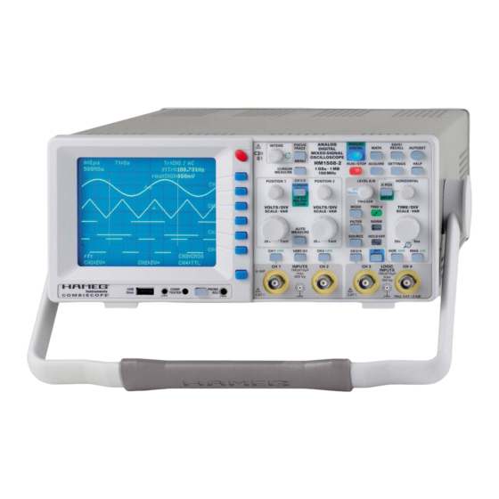
1 5 0 M H z ® M i x e d S i g n a l C o m b i S c o p e H M 1 5 0 8 - 2 Servicemanual English Release: April, 2008... -
Page 2: R2231: 100 Hz Square Wave 5 Mv/Div Ch
HAMEG instruments fulfi ll the regulations of the EMC directive. The conformity test made by HAMEG is based on the actual generic- and 4. RF immunity of oscilloscopes. product standards. In cases where different limit values are applicable, HAMEG applies the severer standard. -
Page 3: A Test Instruments Required
C o n t e n t s CombiScope HM1508-2 Specifi cations Front Panel Elements – Brief Description Blockdiagram Short Description of HM1508-2 Boards 1. TE Board 2. YP Board 3. Delay Line 4. YF Board 5. MB Board 6. FC Board 7. - Page 4 H M 1 5 0 8 - 2 ® 1 5 0 M H z M i x e d S i g n a l C o m b i S c o p e w i t h F F T H M 1 5 0 8 - 2 1 GSa/s Real Time Sampling, 10 GSa/s Random Sampling DSO mode: 4-channel display of 2...
- Page 5 H M 1 5 0 8 - 2 S p e c i f i c a t i o n s Analog mode 2nd Trigger 150 MHz Mixed Signal CombiScope ® HM1508-2 Min. signal height: 5 mm Valid at 23 °C after a 30 minute warm-up period Frequency range: 0 - 250 MHz Coupling:...
- Page 6 HM1508-2E/260107/ce · Subject to alterations · © HAMEG Instruments GmbH · ® Registered Trademark · DQS-certified in accordance with DIN EN ISO 9001:2000, Reg.-No.: DE-071040 QM HAMEG Instruments GmbH · Industriestr. 6 · D-63533 Mainhausen · Tel +49 (0) 6182 800 0 · Fax +49 (0) 6182 800 100 · www.hameg.com · info@hameg.com A Rohde &...
- Page 7 F r o n t P a n e l E l e m e n t s – B r i e f D e s c r i p t i o n Front Panel Elements – Brief Description 9 10 11 12 ANALOG...
- Page 8 F r o n t P a n e l E l e m e n t s – B r i e f D e s c r i p t i o n CH1/2-CURSOR-CH3/4-MA/REF-ZOOM (pushbutton) CH1 / VAR (pushbutton) Calls the menu and indicates the current function of POSI- Calls channel 1 menu with input coupling, inverting, probe TION 1 and 2 controls.
- Page 9 F r o n t P a n e l E l e m e n t s – B r i e f D e s c r i p t i o n ANALOG ANALOG SAVE/ FOCUS INTENS POWER POWER DIGITAL...
- Page 10 B l o c k d i a g r a m H M 1 5 0 8 - 2 10 Subject to change without notice...
- Page 11 S h o r t D e s c r i p t i o n o f H M 1 5 0 8 - 2 B o a r d s The Delay Line stage converts the signal to the wave resistance Short Description of HM1508-2 Boards stage of the delay line.
- Page 12 S h o r t D e s c r i p t i o n o f H M 1 5 0 8 - 2 B o a r d s and time base section are compensated and the trigger slope contacts are recognised and their probe factor is taken into becomes visible.
- Page 13 P C B I n t e r c o n n e c t i o n s PCB Interconnections W6002 W6001 J1008 J4802 J4801 Subject to change without notice...
- Page 14 P C B I n t e r c o n n e c t i o n s Interconnections between: MB-Board (J4801) and YF-Board (W9000) MB-Board (J5002) and MC-Board (J4) Direction Name Direction Name YP-Board (J2400) and MB-Board (J5000) -->...
- Page 15 P C B I n t e r c o n n e c t i o n s PS-Board (J3) and CRT-Board (W6003) MC-Board (J5) and AB-Board (J1) MC-Board (J6) and IF-Board (J8500) Direction Name Direction Name Direction Name -->...
- Page 16 If cables or connectors have to be disconnected, the instrument must be switched off before removing them. For measurement at high voltage (-1.5 kV Focus and -2 kV) use suitable probes, recommended by HAMEG. Such measurements should be performed in the following way: 1.
- Page 17 H M 1 5 0 8 - 2 T r o u b l e s h o o t i n g B: Preliminary Test! 3. Set the front face of the oscilloscope on a soft surface and pull the cabinet off. (Photo A6 and A7) The precondition for undistorted operation is correct supply voltages generated by the power supply.
- Page 18 H M 1 5 0 8 - 2 T r o u b l e s h o o t i n g +5 V IF -2 kV Locate and identify J1005 (1 litz wire) connecting the power Locate and identify Molex connector J1009 (4 wires) connecting supply board with the MC board (marked “+5 V IF”...
- Page 19 H M 1 5 0 8 - 2 T r o u b l e s h o o t i n g +12 kV 1.7.3 Please note that the crt and the voltage multiplier can still be 1.7.1 +12 kV measurement charged although the instrument is switched off.
- Page 20 H M 1 5 0 8 - 2 T r o u b l e s h o o t i n g If the heater seems to be defective, remove the CRT socket and 1.10 Adjustment after power supply change. measure the CRT heater resistance between pin 1 and 14 to The following procedures are required after changing a power eliminate the CRT socket.
- Page 21 H M 1 5 0 8 - 2 T r o u b l e s h o o t i n g Item Instrument Behavior What to do Remark Analog and digital mode: Select analog mode. This description assumes that the crt heater glows as described under item 1.8.
- Page 22 H M 1 5 0 8 - 2 T r o u b l e s h o o t i n g Item Instrument Behavior What to do Remark Measure the sawtooth signal using an oscilloscope with See photos C3.9.1 and C3.9.2 made in analog a *10 probe or alternatively the method described under mode.
- Page 23 H M 1 5 0 8 - 2 T r o u b l e s h o o t i n g Item Instrument Behavior What to do Remark 3.13 Locate and identify delay line cable on YF board and make See photo C3.13 a short across the delay line.
- Page 24 Use an oscilloscope and measure the PUMP_VOL(tage) See photos C5.1.1 and C5.1.2. via a 10:1 probe at pin 2 of Molex connector J1008 after HAMEG logo has a bright the wire to CR board has been disconnected. spot in the top right posi-...
- Page 25 H M 1 5 0 8 - 2 T r o u b l e s h o o t i n g Item Instrument Behavior What to do Remark Use an oscilloscope and measure the control voltage D_ANA at pin See photo C6.4.1.
- Page 26 H M 1 5 0 8 - 2 T r o u b l e s h o o t i n g Item Instrument Behavior What to do Remark If the signal is present, the YP board is ok, continue with item 7.6. If the signal is not present, continue with item 7.7.
- Page 27 Some errors cause a break of the calibration and the display of an error message on the screen. 15.2 Use the Hameg adjustment and testing program “PSH1.xx”, select operation mode „testing“ and select your Instrument (e.g. HM1508-2), run the program and look for errors. .
-
Page 28: Table Of Contents
P e r f o r m a n c e C h e c k H M 1 5 0 8 - 2 Performance Check HM1508-2 Table of Content 5) Pre-attenuator 2:1 (1M Ohm parallel with 10-25 pF), e.g. HZ20 (e.g. -
Page 29: Trace Rotation Check
P e r f o r m a n c e C h e c k H M 1 5 0 8 - 2 Some checks require the presence of software adjustment 6. CH 1: Attenuator Compensation menus. To enter these menus: 1. - Page 30 P e r f o r m a n c e C h e c k H M 1 5 0 8 - 2 8.1 CH1 – 1 mV/div (5% accuracy) 8.8 CH1 – 200 mV/div (3% accuracy) – Set attenuator CH 1 to 1 mV/div. –...
-
Page 31: 2: Y Accuracy
P e r f o r m a n c e C h e c k H M 1 5 0 8 - 2 9. CH 2: Y Accuracy 9.7 CH2 – 200 mV/div (3% accuracy) The accuracy reading should always be performed in the –... -
Page 32: Add Accuracy (5 Mv/Div.)
P e r f o r m a n c e C h e c k H M 1 5 0 8 - 2 9.14 CH2 – 20 V/div (3% accuracy) signal exactly on a horizontal graticule line serving as a –... -
Page 33: 1: 1 Mv/Div. Y-Amplifi Er Bandwidth (Analog/Digital)
P e r f o r m a n c e C h e c k H M 1 5 0 8 - 2 – Adjust the generator amplitude for 8 div. display height on 18. CH 1: 5 mV/div: XY mode X Bandwidth (Analog/Digital) the screen. -
Page 34: 1: Trigger Bandwidth (Internal Triggering)
P e r f o r m a n c e C h e c k H M 1 5 0 8 - 2 22. CH 1: Trigger Bandwidth (internal triggering) – Press “TTL” function key so that the CH 3 trigger threshold –... -
Page 35: Trigger Filter Check
P e r f o r m a n c e C h e c k H M 1 5 0 8 - 2 29. Trigger Filter Check – Set time mark generator for 100μs spike pulses (alterna- – Set time base to 500 μs/div. tively 10 kHz sine wave signal);... - Page 36 A d j u s t m e n t a n d P e r f o r m a n c e C h e c k H M 1 5 0 8 - 2 – The maximum acceptable deviation at the 10 or 11 pulse the fi...
- Page 37 MADE IN GERMANY HZ620 Several types of Box I will be available for connecting to 2-Ch or 4-Ch HAMEG-oscilloscopes. Box I is also named HM1x0xLF- Selecting Signals and Sub Functions Box. Note that some functions of Box I are only accessible via Interface commands.
- Page 38 S y s t e m D e s c r i p t i o n H Z 6 2 0 Calibrating the DC-voltage from –2V to +3V When changing the signal, the activated sub-function is can- celled. The Frequency/Amplitude Encoders are enabled or disabled according to the selected signal.
- Page 39 S y s t e m D e s c r i p t i o n H Z 6 2 0 VID x Ext.Video signal is switched to the output connector Frequency selection: of HZ620, x = 0 >not inverted, 1 > inverted FRQ x x = DC 200Hz...
- Page 40 H M 1 X 0 X O s c i l l o s c o p e s T e s t a n d A d j u s t m e n t 2.3 HM1508-2 (device under test) HM1X0X Oscilloscopes Test and Adjustment Connect the HM1508-2 RS-232 connector to an unused COM Port on the PC and keep the COM Port number in mind.
- Page 41 H M 1 X 0 X O s c i l l o s c o p e s T e s t a n d A d j u s t m e n t 3.2.3 USB Driver selection 3.2.5 Finishing the installation After the installation has been successfully completed it is indicated by the following information.
- Page 42 H M 1 X 0 X O s c i l l o s c o p e s T e s t a n d A d j u s t m e n t 3.2.8 USB Driver selection 3.2.10 Finishing the installation After the installation has been successfully completed it is indicated by the following information.
- Page 43 H M 1 X 0 X O s c i l l o s c o p e s T e s t a n d A d j u s t m e n t 4. PSH Adjustment Software installation 4.3 Installation fi...
- Page 44 Note: The opening of this window is only required to remember the name of the path, to change it or to store a new database version downloaded from “HAMEG Service” which will be loaded with the next STOP start of PSH.
- Page 45 5.7.3.2 Special case: New device. If a new device is to be tested/adjusted, input the device If the calibration has been made in the HAMEG calibration name (type). Thereafter the calibration data of this device lab, a text fi le with the calibration data will be delivered must be input in its allocated calibration database (edit >...
- Page 46 H M 1 X 0 X O s c i l l o s c o p e s T e s t a n d A d j u s t m e n t 5.7.4.5 “device name” Close the window “Device attributes” and connect the Click the “1.
- Page 47 H M 1 X 0 X O s c i l l o s c o p e s T e s t a n d A d j u s t m e n t the presence of the generators (e.g. HM813x and HZ620) number (instrument settings, test function), result (com- and their serial numbers (to avoid the use of uncalibrated mand, fail, pass).
- Page 48 H M 1 X 0 X O s c i l l o s c o p e s T e s t a n d A d j u s t m e n t 5.8.6 “Message” window control functions. The “STOP”...
- Page 49 H M 1 X 0 X O s c i l l o s c o p e s T e s t a n d A d j u s t m e n t Test set up rear connections between PC and Test & Calibration equipment USB-RS232 USB-RS232 USB-Hub...
- Page 50 M A N U A L A D J U S T M E N T P R O C E D U R E H M 1 5 0 8 - 2 M A N U A L A D J U S T M E N T P R O C E D U R E ®...
- Page 51 M A N U A L A D J U S T M E N T P R O C E D U R E H M 1 5 0 8 - 2 Content RV1001: +65 Volt supply 42 Trigger Peak Peak CH 1 (Software Adjustment) RV1003: +12 Volt supply 43 Trigger Peak Peak CH 2 (Software Adjustment) Trace Rotation Check...
- Page 52 M A N U A L A D J U S T M E N T P R O C E D U R E H M 1 5 0 8 - 2 General Informations Analog/Digital Oscilloscope HM1508-2 WARNING The Instrument must be disconnected from the mains power supply whenever you open the case, repair or exchange parts.
- Page 53 M A N U A L A D J U S T M E N T P R O C E D U R E H M 1 5 0 8 - 2 General Informations Adjustment Procedure This procedure covers all adjustments and the most important – but not all – performance checks. The correct sequence of all adjustment steps must be strictly followed.
-
Page 54: Rv1001 +65 Volt Supply
M A N U A L A D J U S T M E N T P R O C E D U R E H M 1 5 0 8 - 2 RV1001 +65 Volt supply WARNING: To avoid damage use a fully insulated screwdriver! –... -
Page 55: Rv1003 +12 Volt Supply
M A N U A L A D J U S T M E N T P R O C E D U R E H M 1 5 0 8 - 2 RV1003 +12 Volt supply WARNING: To avoid damage use a fully insulated screwdriver! –... -
Page 56: Trace Rotation Check
M A N U A L A D J U S T M E N T P R O C E D U R E H M 1 5 0 8 - 2 Trace Rotation Check – Select “Trace Rot.”. –... -
Page 57: R6013: Crt Minimum Intensity
M A N U A L A D J U S T M E N T P R O C E D U R E H M 1 5 0 8 - 2 R6013 CRT minimum intensity WARNING: To avoid damage use a fully insu- lated screwdriver! –... -
Page 58: R6024: Astigmatism Correction
M A N U A L A D J U S T M E N T P R O C E D U R E H M 1 5 0 8 - 2 R6024 Astigmatism correction WARNING: To avoid damage use a fully insu- lated screwdriver! –... - Page 59 M A N U A L A D J U S T M E N T P R O C E D U R E H M 1 5 0 8 - 2 R2031 100 Hz Square Wave 5 mV/div CH 1 –...
-
Page 60: R2025: 100 Hz Square Wave 2 Mv/Div Adjustment
M A N U A L A D J U S T M E N T P R O C E D U R E H M 1 5 0 8 - 2 R2025 100 Hz Square Wave 2 mV/div Adjustment CH 1 –... - Page 61 M A N U A L A D J U S T M E N T P R O C E D U R E H M 1 5 0 8 - 2 R2231 100 Hz Square Wave 5 mV/div CH 2 –...
-
Page 62: R2225: 100 Hz Square Wave 2 Mv/Div Adjustment
M A N U A L A D J U S T M E N T P R O C E D U R E H M 1 5 0 8 - 2 R2225 100 Hz Square Wave 2 mV/div Adjustment CH 2 –... -
Page 63: 1, Input Capacitance Adaptation
M A N U A L A D J U S T M E N T P R O C E D U R E H M 1 5 0 8 - 2 CH 1, Input Capacitance Adaptation – Press AUTOSET pushbutton without signal applied (default setting). –... -
Page 64: C2023: Ch 1, 10:1 Attenuator Compensation
M A N U A L A D J U S T M E N T P R O C E D U R E H M 1 5 0 8 - 2 C2023 CH 1, 10:1 Attenuator Compensation – Locate and identify C-Trimmer C2023 in the shielded CH 1 section of the YP board. -
Page 65: C2017
M A N U A L A D J U S T M E N T P R O C E D U R E H M 1 5 0 8 - 2 C2017 CH 1, 10:1 Attenuator Input Capacitance Adaptation –... -
Page 66: C2004: Ch 1, 100:1 Attenuator Compensation
M A N U A L A D J U S T M E N T P R O C E D U R E H M 1 5 0 8 - 2 C2004 CH 1, 100:1 Attenuator Compensation – Locate and identify C-Trimmer C2004 in the shielded CH 1 section of the YP board. -
Page 67: C2006
M A N U A L A D J U S T M E N T P R O C E D U R E H M 1 5 0 8 - 2 C2006 CH 1, 100:1 Attenuator Input Capacitance Adaptation –... -
Page 68: 2, Input Capacitance Adaptation
M A N U A L A D J U S T M E N T P R O C E D U R E H M 1 5 0 8 - 2 CH 2, Input Capacitance Adaptation – Press AUTOSET pushbutton without signal applied (default setting). –... -
Page 69: C2223: Ch 2, 10:1 Attenuator Compensation
M A N U A L A D J U S T M E N T P R O C E D U R E H M 1 5 0 8 - 2 C2223 CH 2, 10:1 Attenuator Compensation – Locate and identify C-Trimmer C2223 in the shielded CH 2 section of the YP board. -
Page 70: C2217
M A N U A L A D J U S T M E N T P R O C E D U R E H M 1 5 0 8 - 2 C2217 CH 2, 10:1 Attenuator Input Capacitance Adaptation –... -
Page 71: C2204: Ch 2, 100:1 Attenuator Compensation
M A N U A L A D J U S T M E N T P R O C E D U R E H M 1 5 0 8 - 2 C2204 CH 2, 100:1 Attenuator Compensation – Locate and identify C-Trimmer C2204 in the shielded CH 2 section of the YP board. -
Page 72: C2206
M A N U A L A D J U S T M E N T P R O C E D U R E H M 1 5 0 8 - 2 C2206 CH 2, 100:1 Attenuator Input Capacitance Adaptation –... -
Page 73: Readout Adjustment (Software Adjustment)
M A N U A L A D J U S T M E N T P R O C E D U R E H M 1 5 0 8 - 2 Readout Adjustment (Software Adjustment) – Press “PROBE ADJ.” pushbutton, “COMP. TESTER On” function key and press AUTO/CURSOR-MEASURE and SETTINGS pushbutton simultaneously to enter the “Settings Adjust”... -
Page 74: Yp Ch 1 Analog Gain (Software Adjustment)
M A N U A L A D J U S T M E N T P R O C E D U R E H M 1 5 0 8 - 2 YP CH 1 Analog Gain (Software Adjustment) –... -
Page 75: Yp Ch 1 Analog Dc Offset (Software Adjustment)
M A N U A L A D J U S T M E N T P R O C E D U R E H M 1 5 0 8 - 2 YP CH 1 Analog DC Offset (Software Adjustment) –... -
Page 76: Yp Ch 1 Invert Symmetry (Software Adjustment)
M A N U A L A D J U S T M E N T P R O C E D U R E H M 1 5 0 8 - 2 YP CH 1 Invert Symmetry (Software Adjustment) –... -
Page 77: Yp Add Y Position (Software Adjustment)
M A N U A L A D J U S T M E N T P R O C E D U R E H M 1 5 0 8 - 2 YP ADD Y Position (Software Adjustment) – Check that no signal is applied at the BNC connectors. -
Page 78: Position (Software Adjustment)
M A N U A L A D J U S T M E N T P R O C E D U R E H M 1 5 0 8 - 2 X Position (Software Adjustment) – Check that no signal is applied at the BNC con- nectors. -
Page 79: Trigger Point (Software Adjustment)
M A N U A L A D J U S T M E N T P R O C E D U R E H M 1 5 0 8 - 2 Trigger Point (Software Adjustment) – Check that no signal is applied at the BNC connectors. –... -
Page 80: Trigger Counter (Software Adjustment)
M A N U A L A D J U S T M E N T P R O C E D U R E H M 1 5 0 8 - 2 Trigger Counter (Software Adjustment) – Press “Counter” function key to call the “Trigger Counter” submenu. –... -
Page 81: Acquire Ch 1 Interl. Pos. (Software Adjustment)
M A N U A L A D J U S T M E N T P R O C E D U R E H M 1 5 0 8 - 2 Acquire CH 1 Interl. Pos. (Software Adjustment) –... -
Page 82: Acquire Ch 2 Interl. Pos. (Software Adjustment)
M A N U A L A D J U S T M E N T P R O C E D U R E H M 1 5 0 8 - 2 Acquire CH 2 Interl. Pos. (Software Adjustment) –... -
Page 83: Calibrator (Software Adjustment)
M A N U A L A D J U S T M E N T P R O C E D U R E H M 1 5 0 8 - 2 Calibrator (Software Adjustment) – Check that no signal is applied at the BNC connectors. –... -
Page 84: R5107: Comp. Tester Trace Rotation
M A N U A L A D J U S T M E N T P R O C E D U R E H M 1 5 0 8 - 2 R5107 COMP. Tester Trace Rotation Note: This adjustment assumes that the adjustment un- der item 3) “Trace Rotation Check”... -
Page 85: Timebase, Adjust 2 Timebase, A Timebase (Software Adjustment)
M A N U A L A D J U S T M E N T P R O C E D U R E H M 1 5 0 8 - 2 Timebase, Adjust 2 Timebase, A Timebase (Software Adjustment) –... -
Page 86: Timebase, Adjust 2 Timebase, B Timebase (Software Adjustment)
M A N U A L A D J U S T M E N T P R O C E D U R E H M 1 5 0 8 - 2 Timebase, Adjust 2 Timebase, B Timebase (Software Adjustment) –... -
Page 87: Saving Software Adjustments
M A N U A L A D J U S T M E N T P R O C E D U R E H M 1 5 0 8 - 2 Saving Software Adjustments – Check that Settings Adjust menu is displayed. –... -
Page 88: C54 (C27), C63 (C31) Dot Join Adjustment
M A N U A L A D J U S T M E N T P R O C E D U R E H M 1 5 0 8 - 2 C54 (C27), C63 (C31) Dot Join Adjustment –... -
Page 89: R4840: X-Mag. X10 Adjustment
M A N U A L A D J U S T M E N T P R O C E D U R E H M 1 5 0 8 - 2 R4840 X-Mag. x10 Adjustment – Locate and identify R4840 on MB-Board. –... -
Page 90: C4809, C4810: X-Mag. X10 Trace Start Linearity
M A N U A L A D J U S T M E N T P R O C E D U R E H M 1 5 0 8 - 2 C4809, C4810 X-Mag. x10 Trace Start Linearity –... -
Page 91: R9149: Y-Final Amplifi Er Adjustment
M A N U A L A D J U S T M E N T P R O C E D U R E H M 1 5 0 8 - 2 R9149 Y-Final Amplifi er Adjustment – Check that a 1 MHz square wave signal of 25 mV via 50 cable and 50 through termination is connected to input CH 1. -
Page 92: R9118, C9045: Y-Final Amplifi Er Adjustment
M A N U A L A D J U S T M E N T P R O C E D U R E H M 1 5 0 8 - 2 R9118, C9045 Y-Final Amplifi er Adjustment – Connect a 1 MHz square wave signal of 25 mV via 50 cable and 50 through termination to input CH 1. -
Page 93: R9034 / C9001 And R9126 / C9037 Y-Final Amplifi Er Adjustment
M A N U A L A D J U S T M E N T P R O C E D U R E H M 1 5 0 8 - 2 R9034 / C9001 and R9126 / C9037 Y-Final Amplifi... - Page 94 M A N U A L A D J U S T M E N T P R O C E D U R E H M 1 5 0 8 - 2 C2201 HF Adjustment CH 2 – Press VERT/XY pushbutton to call the Vertical menu. –...
-
Page 95: Amplifi Er Bandwidth Check
M A N U A L A D J U S T M E N T P R O C E D U R E H M 1 5 0 8 - 2 Y-Amplifi er Bandwidth Check CH 1 50 kHz 8 div Reference –... -
Page 96: R161, C129: Hf Adjustment Ch 1 A/D Converter Driver
M A N U A L A D J U S T M E N T P R O C E D U R E H M 1 5 0 8 - 2 R161, C129 HF Adjustment CH 1 A/D Converter Driver Amplifi er –... -
Page 97: R162, C105
M A N U A L A D J U S T M E N T P R O C E D U R E H M 1 5 0 8 - 2 R162, C105 HF Adjustment CH 2 A/D Converter Driver Amplifi er –... -
Page 98: Video Trigger Check
M A N U A L A D J U S T M E N T P R O C E D U R E H M 1 5 0 8 - 2 Video Trigger Check – Connect a Composite Video Signal with positive polarity (line and frame content above the sync pulses) to input CH 1. -
Page 99: 3, User Defi Nable Trigger Threshold Check
M A N U A L A D J U S T M E N T P R O C E D U R E H M 1 5 0 8 - 2 CH 3, USER defi nable Trigger Threshold Check –... -
Page 100: 4, User Defi Nable Trigger Threshold Check
M A N U A L A D J U S T M E N T P R O C E D U R E H M 1 5 0 8 - 2 CH 4, USER defi nable Trigger Threshold Check –... -
Page 101: Trigger Bandwidth Check
M A N U A L A D J U S T M E N T P R O C E D U R E H M 1 5 0 8 - 2 Trigger Bandwidth Check – Set time base to 50 ns/div. –... -
Page 102: Input
M A N U A L A D J U S T M E N T P R O C E D U R E H M 1 5 0 8 - 2 Z Input – Check that ANALOG MODE is present. –... - Page 103 Subject to change without notice HAMEG Instruments GmbH © HAMEG Instruments GmbH D-63533 Mainhausen 43-2030-2010 (5) 01042010 Industriestraße 6 A Rohde & Schwarz Company Tel +49 (0) 61 82 800-0 © HAMEG Instruments GmbH D-63533 Mainhausen DQS-Certification: DIN EN ISO 9001:2000 Fax +49 (0) 61 82 800-100 A Rohde & Schwarz Company Tel +49 (0) 61 82 800-0 Reg.-Nr.: 071040 QM sales@hameg.com DQS-Certification: DIN EN ISO 9001:2000 Fax +49 (0) 61 82 800-100 Reg.-Nr.: 071040 QM...
Need help?
Do you have a question about the CombiScope HM1508-2 and is the answer not in the manual?
Questions and answers