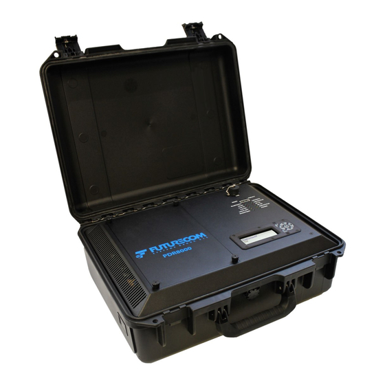
Futurecom PDR8000 Deployment Manual
Portable digital repeater and booster pack
Hide thumbs
Also See for PDR8000:
- Programming manual (98 pages) ,
- Manual (64 pages) ,
- Deployment manual (24 pages)
Table of Contents
Advertisement
Quick Links
Advertisement
Table of Contents

Related Manuals for Futurecom PDR8000


Summary of Contents for Futurecom PDR8000
- Page 1 Futurecom Systems Group, ULC ® PDR8000 Portable Digital Repeater and Booster Pack Deployment Guide ATTENTION! Please read the RF Safety Booklet provided with the product before proceeding with deployment Document: 8K088X03 Revision: R5.04 Date: December 2023...
- Page 2 Printed in Canada. All Rights Reserved Futurecom, PDR8000®, the Futurecom Logo and the Stylized FC logo are registered trademarks of Futurecom Systems Group, ULC. All other trademarks are the property of their respective owner. No part of this document, or any software included with it, may be reproduced and distributed without the prior written permission of the copyright holder.
-
Page 3: Table Of Contents
Step 3 – Connect the External RF Cables and Antenna ........... 28 Step 4 – Connect the Power Cables ................28 Configuration 2 – PDR8000 Internal Duplexer with Booster Pack Configuration .. 29 Step 1 – Preparing PDR8000 for Booster Pack ............29 Step 2 –... - Page 4 Figure 34 - External Duplexer and Booster Pack Hardware Configuration Figure 35 - 8-PIN or 6-PIN PDR8000 AUX Connector Figure 36 - PDR8000 V.24 PinOut specification to connect DIU or CCGW Figure 37 - V.24 Connection between two PDR8000s Figure 38 - DC Power Cable...
-
Page 5: Introduction
PDR8000® Portable Digital Repeater and Booster Pack Deployment Guide 1. Introduction The PDR8000 is typically a self-contained device but is easily modified to utilize an alternate duplexer and/or a transmit power Booster Pack when required. Multiple RF hardware configurations are supported, using accessible internal and external connection points to enable the desired configuration. -
Page 6: Figure 3 - Internal Duplexer And Booster Pack Hardware Configuration
Document 8K088X03 R5.04 PDR8000® Portable Digital Repeater and Booster Pack Deployment Guide Figure 3 - Internal Duplexer and Booster Pack Hardware Configuration Figure 4 - External Duplexer Hardware Configuration Note: External Duplexer Cabling supplied by user Figure 5 - External Duplexer and Booster Pack Hardware Configuration... -
Page 7: Pdr8000 Deployment
Document 8K088X03 R5.04 PDR8000® Portable Digital Repeater and Booster Pack Deployment Guide 2. PDR8000 Deployment Step 1- Internal Connections Determine the required RF hardware configuration and confirm the internal connections correspond to the instructions below. To access the internal connections, unscrew the four corner thumbscrews of the top panel and remove it. -
Page 8: Figure 8 - Duplexer Label (With Indicated Insertion Losses)
Document 8K088X03 R5.04 PDR8000® Portable Digital Repeater and Booster Pack Deployment Guide If the PDR8000 Duplexer is changed, the ‘Duplexer Losses’ field values in FRC must be verified to match the ‘Duplexer Losses’ reading on the Duplexer’s Label for Motorola Duplexers (See Figure 8). -
Page 9: Figure 9 - Pdr8000 Side Panel Cover
Document 8K088X03 R5.04 PDR8000® Portable Digital Repeater and Booster Pack Deployment Guide Step 2- External Connections Based on the required RF hardware configuration, proceed with the external connections as per the instructions below. To access the external connections, pull the release latch and remove the side panel. -
Page 10: Figure 11 - Pdr8000 Side Panel
Screw/Unscrew Dust Cap Ground Lug Green LED Indicator Figure 12 - PDR8000 External Connectors' and LED Specifications LAN port is not enabled on PDR8000 Connector was EGG.1K.306.CLL on releases prior to PDR8000 Release 4 December 2023 Page 10 of 35... - Page 11 • ANTENNA cable is connected to ANTENNA connector • RF cable is connected from RF OUT connector of PDR8000 to RF IN connector of Booster Pack • RF cable is connected from RF IN connector of PDR8000 to RF OUT connector of...
-
Page 12: Step 3A - V.24 Connection (Optional)
(supplied by end user see Appendix A - V.24 Cable) is connected from the V.24 end connector of the PDR8000 to the V.24 system device: DIU (supplied by end user), Modem (supplied by end user), Conventional Channel Gateway (supplied by end user- available as model number SQM01SUM0205 from Motorola Solutions) or another PDR8000. -
Page 13: Step 4- Power
Document 8K088X03 R5.04 PDR8000® Portable Digital Repeater and Booster Pack Deployment Guide Step 4- Power ATTENTION! Please read the RF Safety Booklet Before proceeding with this step. Only proceed with this step once all the other connections are complete. DC Power: •... -
Page 14: Figure 16 - Pull Ac Power Dust Cover
Figure 17 - AC Power Connection to PDR8000 Powering Scheme- both AC (100-240V) and DC (13.8V) can be connected simultaneously. The PDR8000 will dynamically choose the supply with the highest voltage and if one supply fails, the other will take over with an instant transfer of power. -
Page 15: Step 5- Power Up Confirmation
PDR8000® Portable Digital Repeater and Booster Pack Deployment Guide Step 5- Power Up Confirmation If the PDR8000 successfully powers up, the fan will start running and the POWER LED in the bottom right corner of the LED panel will turn on. - Page 16 Document 8K088X03 R5.04 PDR8000® Portable Digital Repeater and Booster Pack Deployment Guide Dedicated Status LEDs The following table contains the state definitions for Dedicated Status LEDs. Label State Status Description LINK QUALITY No Link (wireline interface is off as programmed)
-
Page 17: Figure 20 - Pdr8000 Dedicated Status Leds Definition
Figure 21 - PDR8000 Side LED Definition If the PDR8000 does not successfully power up, the fan will not start running and there will be no lights displayed on the LED light panel. Disconnect the power source and replace the appropriate fuse. -
Page 18: Step 6 - Keypad/Display
PDR8000® Portable Digital Repeater and Booster Pack Deployment Guide Step 6 - Keypad/Display PDR8000 is equipped with an LCD display, providing a means to access and control several aspects of the unit. Access to various functions is available utilizing an on-screen menu, and a set of navigation buttons. -
Page 19: Figure 23 - Pdr8000 Keypad/Display
PDR8000® Portable Digital Repeater and Booster Pack Deployment Guide Figure 23 - PDR8000 Keypad/Display The Display Menu may be configured by the PDR8000 configuration utility program known as the Futurecom Repeater Configurator (FRC). Therefore, any PDR8000 will have the menu specifically configured for the unit. - Page 20 Document 8K088X03 R5.04 PDR8000® Portable Digital Repeater and Booster Pack Deployment Guide The following menu navigation is based on a generic configuration of a PDR8000 unit. Buttons Effect Menu Toggles Menu On/Off (Menu may auto toggle off after a period of time). User would be prompted for password if the menu access is password protected and in locked state.
- Page 21 Document 8K088X03 R5.04 PDR8000® Portable Digital Repeater and Booster Pack Deployment Guide Main Menu Sub-Menu Action/Info >CHANNELS >List of Channels View/Select Active Channel <List of Deployment Profiles >DEPLOYMENTS View/Select Active Deployment Profiles View/Set Display’s Contrast Level >SETTINGS >CONTRAST View/Set Display’s Brightness Level >BRIGHTNESS...
- Page 22 Document 8K088X03 R5.04 PDR8000® Portable Digital Repeater and Booster Pack Deployment Guide >ABOUT > PDR 8000 Product Name > SN: xxxxxxxx Product serial number > HW PN: 7V083X01 Hardware part number > HW REV: xx.xx Hardware revision > HW REL: dd/mm/yy Hardware release date >...
-
Page 23: Step 7 - Open/Closed Case Operation
PDR8000 should be standing on its hinged side, allowing the case to provide better cooling efficiency. When operating open-case (providing the best cooling capability), the PDR8000 is to be placed flat on its large surface. Note that the PDR8000 is not water resistant when operating open-case. -
Page 24: Booster Pack Deployment (Optional)
Booster Pack transmits a constant power level. Therefore, with the duplexer connected, the power at the PDR's antenna port is the power at the PDR8000’s RF Out port plus duplexer losses. For example: if the Booster Pack’s output power is 45dBm and the duplexer loss is - 1.5dB, the output power at the PDR8000's antenna port is 43.5dBm. -
Page 25: Booster Pack External Connections
Document 8K088X03 R5.04 PDR8000® Portable Digital Repeater and Booster Pack Deployment Guide Figure 26 - Booster Pack Booster Pack External Connections Figure 27 - Booster Pack External Connections Label Type Manufacturer Model Ref* Open/Close Mechanism RF OUT N Female Screw/Unscrew Dust Cap... -
Page 26: Figure 28 - Booster Pack External Connectors' And Led Specifications
Document 8K088X03 R5.04 PDR8000® Portable Digital Repeater and Booster Pack Deployment Guide 13V/14.3A DC DC Power Input LEMO EGL.2K.30 Push Pull Dust Cap 2.CLA Ground Lug Green LED POWER Indicator Toggle Switch M2012LL3 Pull out / Toggle switch for power LED to operate... -
Page 27: Configuration 1 - Simplex With Booster Pack Configuration
Step 1 – Preparing PDR8000 for Booster Pack Use this configuration when PDR8000 does not have a duplexer and is intended to be used in a Simplex operation with a single antenna. The following steps shall be followed in sequence and is depicted in Figure 30. -
Page 28: Step 3 - Connect The External Rf Cables And Antenna
(refer to Figure 30 for wiring diagram) 1. Connect an RF cable to ANT port on the side panel of PDR8000 and the other end of it to RF IN connector on the Booster Pack’s side panel 2. -
Page 29: Configuration 2 - Pdr8000 Internal Duplexer With Booster Pack Configuration
Figure 32 - Internal Duplexer and Booster Pack Hardware Configuration Note 1: If the PDR8000 Duplexer is changed, the ‘Duplexer Losses’ field values in FRC must be verified to match the ‘Duplexer Losses’ reading on the Duplexer’s Label (for Motorola Duplexers). For Duplexers from different manufacturer, please refer to the manufacturer’s specification for Duplexer losses and enter them into the FRC ’Duplexer Losses’... -
Page 30: Step 3 - Connect The External Rf Cables And Antenna
RF IN connector on the Booster Pack’s side panel 2. Connect an RF cable to RF IN port on the side panel of PDR8000 and the other end of it to RF OUT connector on the Booster Pack’s side panel 3. -
Page 31: Configuration 3 - Pdr8000 External Duplexer With Booster Pack Configuration
Figure 34 - External Duplexer and Booster Pack Hardware Configuration Note 1: If the PDR8000 Duplexer is changed, the ‘Duplexer Losses’ field values in FRC must be verified to match the ‘Duplexer Losses’ reading on the Duplexer’s Label (for Motorola Duplexers). For Duplexers from different manufacturer, please refer to the manufacturer’s specification for Duplexer losses and enter them into the FRC ’Duplexer Losses’... -
Page 32: Step 2 - Connect The Aux Cable
RF IN connector on the Booster Pack’s side panel 2. Connect an RF cable to RF IN port on the side panel of PDR8000 and the other end of it to RX connector on the external duplexer 3. -
Page 33: Appendix A - V.24 Cable
Data RX Input Data TX Output Input Output Figure 36 - PDR8000 V.24 PinOut specification to connect DIU or CCGW 2) Another PDR/Repeater as per the cross over connection shown in the pin-outs below. Signal Name Pin Num Type Signal Name... -
Page 34: Appendix B - Dc Cable
Appendix B - DC Cable The DC cable shipped with the PDR8000 has a connector on one end and flying leads on the other. To complete the cable, connect the black wire to ground and the red wire to +13.8V. -
Page 35: Appendix C - List Of Acronyms
Used for connecting the PDR to the programming PC. A digital link described as a physical V.24 link with HDLC (High-level V.24 Data Link Control). Used to connect PDR8000 to other infrastructure elements (e.g., CCGW, DIU, comparator) December 2023 Page 35 of 35...
Need help?
Do you have a question about the PDR8000 and is the answer not in the manual?
Questions and answers