Advertisement
Quick Links
Cautions and Warnings
Introduction
In this Publication
2000 Simplex Time Recorder Co., Westminster, MA 01441-0001 USA
All specifications and other information shown were current as of publication, and are subject to change without notice.
IDNet is and TrueAlert are trademarks of Simplex Time Recorder Company.
DO NOT INSTALL ANY SIMPLEX PRODUCT THAT APPEARS
DAMAGED. Upon unpacking your Simplex product, inspect the contents of the
carton for shipping damage. If damage is apparent, immediately file a claim
with the carrier and notify Simplex.
ELECTRICAL HAZARD - Disconnect electrical power when making any
internal adjustments or repairs. Servicing should be performed by qualified
Simplex Representatives.
STATIC HAZARD - Static electricity can damage components. Therefore,
handle as follows:
1.
Ground yourself before opening or installing components (use the 553-484
Static Control Kit).
2.
Keep components not mounted in the panel wrapped in anti-static material.
RADIO FREQUENCY ENERGY - This equipment generates, uses, and can
radiate radio frequency energy and if not installed and used in accordance with
the instruction manual, may cause interference to radio communications. It has
been tested and found to comply with the limits for a Class A computing device
pursuant to Subpart J of Part 15 of FCC Rules, which are designed to provide
reasonable protection against such interference when operated in a commercial
environment. Operation of this equipment in a residential area may cause
interference in which case the user at his own expense will be required to take
whatever measures may be required to correct the interference.
The 4009-9201 (120VAC) or 4009-9301 (220/240VAC) IDNet
Appliance Circuit (NAC) Extender is a self-contained adjunct panel for use with
Simplex Fire Alarm Control Panels (FACPs). The base version of the 4009 IDNet
NAC Extender (4009 IDNet) is a single-board system consisting of four NACs, a
power supply and charger, an IDNet slave interface, and two conventional NAC
inputs for hardwired control (not applicable to the 4009 IDNet as an IDNet device).
Option cards are available to provide the following additional capabilities:
•
4009-9808 Class A Adapter Option Card - allows fault tolerance in the case of
open circuit wiring faults on the NACs.
•
4009-9807 NAC Option Card - adds four conventional Notification Appliance
Circuits.
•
4009-9809 IDNet Repeater Option Card - regenerates and provides a power and
distance boost for the IDNet channel. When IDNet Repeater Option Card is
used, the fiber option is not available to the 4009 IDNet.
•
4009-9810 (Class B)/4009-9811 (Class A) Fiber Optic Receiver - receives
IDNet communication over a fiber optic channel and regenerates the IDNet
signal. The fiber option is used with the 4090-9105 (Class B)/4090-9107
(Class A) Fiber Optic Transmitter to form an IDNet fiber link.
Introduction
4009 IDNet Configuration
Hardware Components
System Configuration
System Switches and Indicators
4009 IDNet Option Interfaces
System Installation
4009 IDNet
Installation Instructions
Topic
NAC Extender
Notification
See page #
1,2
2,3
4
5
5 - 9
9,10
11 - 15
574-181
Rev. B
Advertisement

Related Manuals for Simplex IDNet 4009

Summary of Contents for Simplex IDNet 4009
- Page 1 Notification Appliance Circuit (NAC) Extender is a self-contained adjunct panel for use with Simplex Fire Alarm Control Panels (FACPs). The base version of the 4009 IDNet NAC Extender (4009 IDNet) is a single-board system consisting of four NACs, a power supply and charger, an IDNet slave interface, and two conventional NAC inputs for hardwired control (not applicable to the 4009 IDNet as an IDNet device).
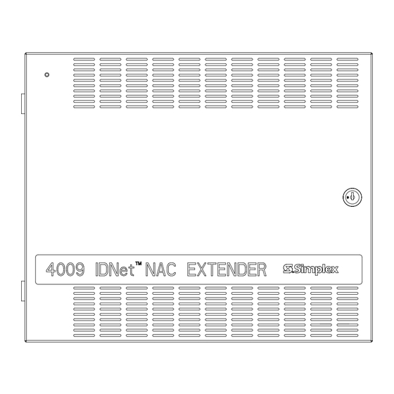
- Page 2 Figure 1. Simplex 4009 IDNet NAC Extender (4009 IDNet) 4009 IDNet Configuration When the desired options have been installed in the 4009 IDNet, set the Hardware Configuration Switch SW1 to match the installed options (see Table 1).
- Page 3 There are two hardwired NAC control inputs to the 4009 IDNet (when used as an IDNet device on a 4010 these inputs are not used). The hardwired NAC control inputs provide backward compatibility with other Simplex panels. In the hardwired mode, the 4009 IDNet is non-addressable and controlled via two DIP switches (Hardware Configuration Switch SW1 and Software Address/Configuration Switch SW2).
- Page 4 4009 IDNet NAC Extender, Continued Hardware Components NAC (Notification Appliance Circuit) Outputs The 4009 IDNet system board provides 4 hardwired NACs. NACs 1 through 4 are Class B, reverse polarity Notification Appliance Circuits. Each circuit has one polarity for supervision state and the opposite polarity for alarm state. Field wiring terminations are provided for 12 AWG - 18 AWG wire.
-
Page 5: System Configuration
4009 IDNet NAC Extender, Continued System Configuration A functional block diagram depicting the interconnections between modules is shown in Figure 3. Alarm signal and 0V connections provide alarm and trouble operation. The host FACP can detect EARTH faults on any NAC signal. Notes: 1. - Page 6 4009 IDNet NAC Extender, Continued SW2 SOFTWARE HARDWARE CONFIGURATION ADDRESS/CONFIGURATION IDNet CONTROL INTERFACE DIP SWITCH DIPSWITCH TB1, TB2 HARDWIRED NAC (NAC 1-4) P1 AND P2 4-CIRCUIT NAC CLASS A ADAPTER OPTION CARD INTERFACE INTERFACE LED(s) 1-4 LED(s) 5-8 NAC STATUS SYSTEM TROUBLE INDICATORS INDICATORS...
- Page 7 4009 IDNet NAC Extender, Continued System Switches and Note: DIP switch in “1” position is “ON” while DIP switch in “0” position is Indicators, continued “OFF”. DIPSWITCH IS SHOWN SET AT ADDRESS 7. 1 = ON 0 = OFF DIP SWITCHES 5 THRU 8 0000 1000 0100 1100 0010 1010 0110 1110 0001 1001 0101 1101 0011 1011 0111 1111 112 128 144 160 176 192 208 224 240 0000...
- Page 8 4009 IDNet NAC Extender, Continued System Switches and Table 3. Control Mapping Switch Settings Indicators, continued DIP Switch SW2 Host NAC Power Distribution to Position Input NAC Circuits 1,2 (5 & 6) 3, 4 (7 & 8) 1 – 4 5 –...
- Page 9 4009 IDNet NAC Extender, Continued System Switches and AC Power Indicator (LED 9) Indicators, continued This green LED indicates that AC power is present and is being used as the 4009 IDNet power source. The 4009 IDNet is switched to batteries whenever the green LED is “OFF”.
- Page 10 4009 IDNet NAC Extender, Continued Fiber Receiver Card (565-903 Class B or 565-902 Class A) and Fiber 4009 IDNet Option Interfaces, Transmitter Card (565-901 Class B or 565-900 Class A) continued The IDNet Fiber Transmitter and 4009 IDNet Fiber Receiver work together to form a fiber optic link from an IDNet run to a remote 4009 Addressable NAC.
-
Page 11: System Installation
Be sure that you are thoroughly familiar with this material before installing your 4009 IDNet. To help you with installation of this and other Simplex Fire Alarm equipment, the following publication is available for general reference: How to Wire a Building for a Fire Alarm System (FA2-91-001 or 575-892). - Page 12 The following pages provide a detailed description of the installation. If you experience problems that cannot be resolved, call your local Simplex Branch Office. Use the following procedure when mounting a 4009 IDNet. CAUTION: Read all instructions carefully before cutting conduit/service entrances and installing back box.
- Page 13 System Installation, Continued Mount back box to wall. Back box must be level and plumb. For surface Mounting the 4009 IDNet, mounting use the teardrop and clearance holes located in the rear of the box continued and screw to wall. Wire Non-Power-Limited wiring in the shaded areas only (see Figure 6), this includes AC input and battery connections.
-
Page 14: System Power Requirements
System Installation, Continued System Power Requirements Model 4009-9201 NAC (120VAC System) AC Input - 120VAC, 3 amperes, 60Hz Battery Input - 24VDC, 8 amperes Notification Appliance Power Output - 24VDC, 8 amperes Model 4009-9301 NAC (220/240 System) AC Input - 220/240VAC, 1.5 amperes, 50/60Hz Battery Input - 24VDC, 8 amperes Notification Appliance Power Output - 24VDC, 8 amperes Notes:... - Page 15 System Installation, Continued Mounting and Wiring Refer to the 842-068 Field Wiring Diagram for detailed information, and the Peripheral Devices procedure listed below when installing the 4009 IDNet peripheral devices. Determine the mounting locations of the peripheral devices and install system wires from the mounting location of each peripheral device to the 4009 system board.
- Page 16 574-181 Rev. B...
Need help?
Do you have a question about the IDNet 4009 and is the answer not in the manual?
Questions and answers