
Summary of Contents for Microfluidics Microfluidizer LM20
- Page 1 LM20 Microfluidizer™ Processor User Manual 90 Glacier Drive Suite 1000 Westwood, MA 02090 Phone 1-800-370-5452 Fax 617-965-1213 www.microfluidicscorp.com ©Copyright 2015 •All Rights Reserved •Printed in U.S.A.
-
Page 2: Important Information
Equipment is capable of operation at altitudes up to 1000M above sea level. ◊ Wear appropriate personal protection devices when operating and servicing equipment. ◊ Read and understand this manual before operating equipment. Contact Microfluidics Customer Service with any questions. ◊ Equipment must be properly maintained and serviced. -
Page 3: Table Of Contents
Contents Important Information ..........................2 Revision History ............................6 Model Specifications ..........................7 Chapter 1: Introduction ..........................8 1.1 Inside this Manual ..........................8 1.2 Disclaimers ............................8 1.2.1 Design Change ..........................8 1.2.2 Reproduction ..........................8 1.2.3 Shipping ............................8 1.3 Customer Support .......................... - Page 4 3.8.1 Hydraulic System ........................15 3.8.2 Utility Hookups ........................... 15 3.8.3 Assembly ............................ 16 3.8.4 Preparing Processor for Operation .................... 16 3.9 Operating the Equipment ......................... 16 3.9.1 Prime the Intensifier Pump ......................17 3.10 Cleaning and Storing the Equipment ....................17 3.11 Using the Emergency Stop ......................
- Page 5 Charging Hydraulic Accumulator ....................30 Chapter 5: Troubleshooting ........................32 Monitoring The Flow Rate ......................32 Unplugging The Chamber(s)......................32 Maintaining Connections & Fittings .................... 32 Symptom and Remedy Table ....................33 5.5 Fault Tree ............................34 5.6 Error Codes ............................ 37 Appendix A: Tool Kit ..........................
-
Page 6: Revision History
Revision History REVISION DATE DESCRIPTION OF CHANGES 2015 • Initial release 2020 • Updated based on design changes Jan-2023 Updated graphics (section 2.4) • MANUAL.LM20 Revision C January 2023 Page 6 of 52... -
Page 7: Model Specifications
Model Specifications Maximum Product Process Pressure (LM20-20) 20,000 psi (1,379bar) Maximum Product Process Pressure (LM20-30) 30,000 psi (1,585bar) Process/Hydraulic Pressure Ratio 21 : 1 Plunger Stroke Length 2.5" (6.35cm) Plunger Seal Material UHMWPE Plunger Diameter 0.437” (1.1cm) Approx. Stroke Displacement 0.375 in3 (6.0mL) Min. -
Page 8: Chapter 1: Introduction
1.2 Disclaimers Design changes and product improvements may subject information in this manual to change without notice. Microfluidics reserves the right to change the design at any time, which may subsequently affect the contents of this manual. 1.2.1 Design Change Microfluidics will make every reasonable effort to ensure that this User’s Manual is up-to-date and... -
Page 9: Chapter 2: Overview
2.1 General Description Microfluidics’ LM20 Microfluidizer Processor is designed for the high-performance micro-mixing of emulsions and dispersions in a variety of industries. The LM20 model is specifically designed to suit laboratory environments. -
Page 10: Component Descriptions
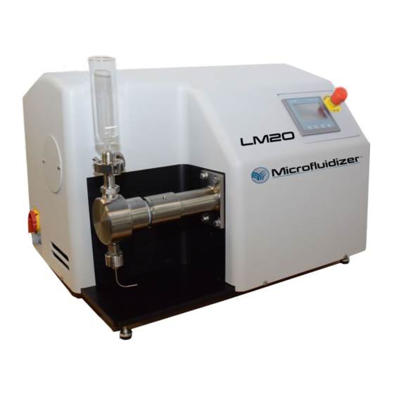
2.4 Component Descriptions MANUAL.LM20 Revision C January 2023 Page 10 of 52... - Page 11 Figure 1 – LM20 Overview Diagram – shown with optional accessories Standard Features (shown in Figure 1): 1. Machine Name Plate: Details model information and serial number. 2. Cover Fasteners: Secures the cover to the base plate. 3. Air Ventilation Inlet: Air inlet for the hydraulic cooling system. Do not obstruct air path, or system damage will occur.
-
Page 12: Chapter 3: Operation
UNDER PRESSURE OR WHEN IT IS RUNNING. WARNING: DO NOT USE DAMAGED MICROFLUIDIZER PPROCESSOR EQUIPMENT OR EQUIPMENT THOUGHT TO BE DAMAGED. ALWAYS USE MICROFLUIDICS GENUINE PARTS. WARNING: DO NOT RESTRICT OR DEAD-END PIPING AFTER THE INTERACTION CHAMBER. BODILY INJURY COULD OCCUR. -
Page 13: Supplied Items
LM20’s power cord. • Nitrogen Charging Kit. The nitrogen charging kit is available from your local Microfluidics representative with the correct local nitrogen adapter. Kits are available for purchase from Microfluidics, contact Microfluidics Customer Service. -
Page 14: Site Preparation
Figure 2 - Site Preparation 3.4 Site Preparation Locate the desired operating site and prepare sufficient space for the equipment (refer to Figure 2). • • Never place base plate directly on flat surface, always operate unit with the 4 leveling machinery feet provided to allow air exhaust to vent properly. -
Page 15: Moving The Equipment
3.5 Moving the Equipment Care shall be taken when moving the processor. Only lift from the bottom base plate, do not lift from any mounted or attached components. Make certain a lifting device is rated for the maximum weight of the equipment (including accessories). -
Page 16: Assembly
3.8.3 Assembly Assemble optional and/or shipped loose components to the LM20 1. The inlet reservoir should be assembled. The O-Ring for the glass reservoir must be lubricated prior to installing the glass reservoir into the metal adapter. 2. Chamber and piping should be assembled. Tighten all high pressure fittings per applicable drawing contained in the turn over documentation. -
Page 17: Prime The Intensifier Pump
NOTE: Do not allow any of the high pressure fitting to leak. Leaking will cause damage to the sealing surfaces of the joint. If a high pressure fitting is leaking, follow the relevant steps in the Maintenance section of this manual. 3.9.1 Prime the Intensifier Pump Priming the intensifier pump is often needed before the first time use, after disassembly, or whenever the Intensifier Pump loses its prime. -
Page 18: Using The Emergency Stop
3.11 Using the Emergency Stop At any time when operating the Microfluidizer Processor, pressing the Emergency Stop Button will stop the intensifier pump and turn off the electric motor, setting the processor to a low energy. To re-set the E-Stop: 1. -
Page 19: Info Screen
3.12.2 Info Screen Figure 4 - Info Screen 1. Batch Stroke Counter: The number of strokes during the batch. Use “RESET” button to reset to zero. 2. Service Stroke Counter: Number of strokes since last qualified service visit. Can only be reset by trained MFIC representatives. -
Page 20: Alarm Screen
3.12.3 Alarm Screen Figure 5 - Alarm Screen 1. E-Stop Reset: After twisting the E-Stop button, press the RESET button to completely reset the E-Stop event. 2. E-Stop Status Light: Red indicates an active E-stop alarm. Green indicates no E-Stop alarm. 3. -
Page 21: Language Screen
3.12.4 Language Screen Figure 6 - Language Screen Select the language by clicking on the appropriate flag. MANUAL.LM20 Revision C January 2023 Page 21 of 52... -
Page 22: Chapter 4: Maintenance
A filter service schedule and hydraulic oil service schedule are included as well as procedures for making hydraulic adjustments. • All stainless steel threaded connections should be lubricated. Microfluidics recommends Never- Seez food grade compound. Always make sure that the system pressure is relieved before servicing. -
Page 23: Removing The Bearing Retainer And Bearing
4.1.2 Removing the Bearing Retainer and Bearing 1. Remove the bearing retainer. First place the pump body in a vise. It is recommended that the vise teeth be made of brass. Wrap the pump body in a rag or cloth so that the vise teeth do not scratch or damage the pump body. -
Page 24: Removing The Plunger
Picture 3 - Seal Removal 10. Remove the seal removal rod, seal and back-up ring. 11. Rinse the pump body seal cavity with water, and dry. Also rinse the seal cavity with isopropyl alcohol or a suitable liquid. Do not use harsh chemicals or rough tools or brushes, as they can damage the pump body. -
Page 25: Cleaning Components
NOTE: If great difficulty is experienced trying to remove the snap retaining ring, it may be necessary to remove the hydraulic extension adapter first. If so, follow steps 6 through 7. To remove the hydraulic cylinder extension adapter from the hydraulic cylinder, apply localized heat to approximately 250ºC on the extension adapter. -
Page 26: Install New Plunger Seal And Back-Up Ring
should be sandwiched between the hydraulic cylinder and the isolator). It is recommended that the bolts be tightened in an X pattern. It is also recommended if available, to place a level on the isolator to insure proper installation. 2. Always lubricate all threaded components and metal to metal contact surfaces with Never-Seez. Failure to lubricate parts may result in galling of components. -
Page 27: Check Valve Maintenance
Picture 4 - Install Pump Body 3. Obtain the spanner wrench (P/N 16.2102) and wrap it around the 2.75" diameter locknut. Make sure the wrench tooth is inserted into one of the locknut grooves. Strike the end of the spanner wrench handle with a rubber head mallet. -
Page 28: Repairing Inlet Check Valve
If cleaning with the appropriate chemical and the use of the MPPC does not resolve the problem, or if the product is leaking out from the inlet fitting threads, then the check valve has to be disassembled. Access to the Check Valve is gained by unscrewing the inlet fitting of the pump. Remove the pump body (Section 4.1.1) and place in a vise. -
Page 29: Replacing Hydraulic Oil
4.3 Replacing Hydraulic Oil With the exception of changing oil, repair or disassembly of the hydraulic components requires special tools and training. Call our Customer Service Dept. at 1-800-370-5452 for further instructions. "CAUTION": Oil must be replaced if it becomes overheated (hotter than 150°F, 65°C) or contaminated. Failure to do so will damage the hydraulic pump and/ or other hydraulic components. -
Page 30: High Pressure Connections
4.4 High Pressure Connections If a coned and threaded connection is not prepared correctly, a leak will be evident through a weep hole (every coned and threaded connection has a weep hole). Usually leaks can be stopped by simply retightening the gland nut. However, if retightening the gland nut does not stop the leak, the connection MUST be taken apart, cleaned, and reassembled. - Page 31 Picture 6 - Charging Accumulator 7. Let the pre-charge set for 10 to 15 minutes. This will allow the gas temperature to stabilize. If the desired pre-charge is exceeded, close nitrogen bottle valve, then slowly open bleed valve (Figure 7). Do not reduce pre-charge by depressing valve core with a foreign object. High pressure may rupture rubber valve seat.
-
Page 32: Chapter 5: Troubleshooting
Chapter 5: Troubleshooting 5.1 Monitoring The Flow Rate An initial flow rate of the product at a base line process pressure (10,000psi) should be done when the unit is received. This will provide a reference point if it is necessary to compare product flow rate data in the future. -
Page 33: Symptom And Remedy Table
CAUTION: Do not over tighten these fittings as excessive torque will deform the metal to metal sealing surface. Damage to the sealing surfaces of the tubing or the fitting seat will result in leakage through the weep hole in the fitting. 5.4 Symptom and Remedy Table Symptom Possible Cause... -
Page 34: Fault Tree
5.5 Fault Tree The Operator Interface Screen is not powered Is the processor plugged into proper electrical supply? Plug processor into proper electrical supply Is the electrical disconnect in the ON position? Turn the disconnect switch to the ON position Contact Customer Service for additonal troubleshooting... - Page 35 MANUAL.LM20 Revision C January 2023 Page 35 of 52...
- Page 36 MANUAL.LM20 Revision C January 2023 Page 36 of 52...
-
Page 37: Error Codes
5.6 Error Codes Movement Fault - Machine has built pressure (based on switch) and Intensifier Cycle is running, but Position Limit Switch has not been on for more than the user changeable amount of time. Low Hydraulic Pressure Fault - Intensifier Cycle is running and the machine has not built pressure in user changeable amount of time (Pressure Switch Input has not turned on). -
Page 38: Appendix A: Tool Kit
Appendix A: Tool Kit The Tool Kit includes all special tools that are needed to service the LM20 Microfluidizer . For a complete bill of material consult the turn over documentation CD. Tool Kit Part Number: 90.10082 Notes: ______________________________________________ ______________________________________________ ______________________________________________ ______________________________________________ ______________________________________________... -
Page 39: Appendix B: Options / Spare Parts
Appendix B: Options / Spare Parts This Microfluidizer also includes a basic set of spare parts. For a complete bill of material for the basic spare parts consult the turn over documentation CD. Any additional options that were purchased will be included in the turn over documentation CD. Spare Parts Part Number: 90.10083 Notes: ______________________________________________... -
Page 40: Appendix C: Drawings
Appendix C: Drawings The turn over documentation CD/USB that is included with the LM20 Microfluidizer contains all the necessary drawings. Notes: ______________________________________________ ______________________________________________ ______________________________________________ ______________________________________________ ______________________________________________ ______________________________________________ ______________________________________________ ______________________________________________ ______________________________________________ ______________________________________________ MANUAL.LM20 Revision C January 2023 Page 40 of 52... -
Page 41: Appendix D: Fluid Compatibility Tables
Appendix D: Fluid Compatibility Tables The following table is compiled primarily from data published by several manufacturers of elastomers and plastics. The ratings are intended only as a guide. In fact, different sources do not always agree, so it is best to test before committing to a particular compound. - Page 42 PEEK: Polyetheretherketone, one of the new high-strength engineering plastics. Has excellent chemical resistance and structural properties. Very high temperature capability. Used for bearings, gaskets, and back-up rings. PTFE: (Trade name, Teflon) Has broadest chemical resistance of all plastic materials and outstanding temperature capability. Limited strength and poor shape retention make PTFE a poor choice for sealing and load bearing applications unless combined with other fillers such as glass fibers, carbon graphite, or molybdenum disulfide.
-
Page 43: Table Of Compatibility
D.3 Table of Compatibility MANUAL.LM20 Revision C January 2023 Page 43 of 52... - Page 44 MANUAL.LM20 Revision C January 2023 Page 44 of 52...
- Page 45 MANUAL.LM20 Revision C January 2023 Page 45 of 52...
- Page 46 MANUAL.LM20 Revision C January 2023 Page 46 of 52...
- Page 47 MANUAL.LM20 Revision C January 2023 Page 47 of 52...
- Page 48 MANUAL.LM20 Revision C January 2023 Page 48 of 52...
- Page 49 MANUAL.LM20 Revision C January 2023 Page 49 of 52...
-
Page 50: Appendix E: Ce Information
Appendix E: CE Information This equipment is manufactured exclusively for Microfluidics by: Quadro Engineering 613 Colby Drive Waterloo, ON N2V 1A1, Canada See CE Certificate in attached Turn Over Documentation MANUAL.LM20 Revision C January 2023 Page 50 of 52... -
Page 51: Appendix F: Maintenance Schedule
Appendix F: Maintenance Schedule To maintain the good performance, Microfluidics International Corporation recommends establishing a routine maintenance schedule, typically done annually, but we do have customers with heavy-daily usage, who schedule bi-annual preventive maintenance proposals or possibly more. Some of the benefits of...
Need help?
Do you have a question about the Microfluidizer LM20 and is the answer not in the manual?
Questions and answers