Table of Contents
Advertisement
Advertisement
Table of Contents

Related Manuals for FREUCAMP W5000

Summary of Contents for FREUCAMP W5000
- Page 1 福莱康普 Cassette Toilet User & Installation Manuals Model: W5000 适用型号:W5000...
-
Page 4: Table Of Contents
Contents User Security considerations Main components Before use Control panel logo & indicator Toilet Use Emptying the waste-holding tank Routine Maintenance Maintenance and cleaning Winter use When this product is left unused Installation Technical specifications Installation dimensions Accessories list Service door installation Installation Connecting electricity Install the vent hose &... -
Page 5: Security Considerations
Security considerations Please read this manual carefully before installation and install it in strict accordance with this manual. After reading, please keep this manual properly. In order to avoid injury or property damage to users and others, please strictly observe the safety warnings and cautions. -
Page 6: Main Components
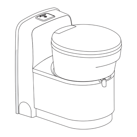
Main components Toilet Decorative pieces Console Control panel Cover Seat Swiveling toilet bowl Blade handle Bottom base Automatic pressure release vent Waste-holding tank Gasket Vent button Pull handle Wheel Tank Blade opener Sliding cover Pour out spout... -
Page 7: Before Use
Before use Ensure that all packaging materials have been removed. 1. Remove the waste-holding tank through the service door. 2. Place the waste-holding tank upright and turn the pour out spout upwards. Remove the cap from the pour out spout. 3. -
Page 8: Control Panel Logo & Indicator
Control panel logo & indicator Flush button Status light Status light Flush button: Press and hold it to flush the toilet. Release it to stop flushing. Light off: Indicates the holding tank is not full and it can be used normally. Flashing red light: Indicates the holding tank is full, need to empty it on time. -
Page 9: Emptying The Waste-Holding Tank
Emptying the waste-holding tank The waste-holding tank has liquid level indicator and water full alarm. When the left light on the control panel blinks red, you will hear a series of beeps by pressing the flushing button, it means the waste-holding tank is too full and must be emptied. When the alarm sound appears, the flushing button will stop after 5s delay. -
Page 10: Maintenance And Cleaning
3. How to use Freucamp cleaner. Daily use of Freucamp cleaner on the waste-holding tank to achieve the effect of degradation paper, sterilization and deodorization. Unscrew the plastic cap directly, add 2 caps (100ml) and 2L of water into the waste-holding tank. -
Page 11: Winter Use
2. Press and hold the flush button of the toilet until no water rushes out. 3. Empty and dry the waste-holding tank. 4. Rinse and dry the entire toilet thoroughly. 5. Slide the waste-holding tank back into its original position and close the blade. Technical specifications Model W5000 Direction Dimensions(mm) Net weight(kg) Capacity waste-holding 17.2... -
Page 12: Installation Dimensions
Installation dimensions Unit: mm ≥185... -
Page 13: Accessories List
Accessories list Toilet 3J-PHD-3# service door Screws ST3.5*25mm Screws ST4.2*25mm Wall bracket Square pipe Screws ST4.2*13mm Decorative pieces Screws ST4.5*55mm Vent hose & Flange Degradation liquid User Manual... -
Page 14: Service Door Installation
Service door installation 1. Door dimensions. Unit: mm 2. Opening position Suitable wall thickness30-50mm Interior floor... - Page 15 Service door installation 3. Service door installation. This product is only suitable for flat wall installation. And other special walls need to be treated flat before installation. The four sides of the opening must be solid enough to bear the door installation strength. Installation steps: Unit: mm Door opening dimension...
-
Page 16: Installation
Installation 1. Install the Unit: mm shower tray (if applicable). 2. Mount the wall bracket to the outside wall with three screws ST4.2*13mm, connecting the toilet to the wall bracket. Unit: mm Recommended distance between the wall bracket screws and the installation floor: 518mm (The actual installation may need to adjust the position appropriately). - Page 17 Installation 3. Mount the toilet to the floor with four screws ST4.5*55mm. Required torque (for a plywood floor): 1.2±0.3N.m. Torque may differ if the floor is made from a different material. 4. Connecting the water hose. Length from the last fixed point: 300mm Diameter Inside: 10mm Outside: 16.5mm Min.: 0.35bar at 4.2L/min...
-
Page 18: Connecting Electricity
Installation 5. Adjust flush pressure (if applicable). Meet the required pressure for the remote pump at the toilet inlet to ensure correct flush. If the pressure is too high, use a slotted screwdriver to adjust the “water pressure control” knob on the solenoid valve. - Page 19 Connecting electricity 2. Use the following parameters to connect the power supply correctly. Connector 4 terminal blocks Blue Brown Position wiring Black Blue Brown Black Cable connections when the toilet is connected to a 4 terminal blocks pressure system 12V DC The red cable is positive.
-
Page 20: Install The Vent Hose & Flange
Ø9mm Console removal Remove the W5000 console as follows: 1. Remove all the screws that secure the 2. Remove the waterproof connector of solenoid backboard and keep them properly. valve. - Page 21 Console removal 4. Remove the three waterproof joints as 3. Remove the fuse bracket and side cover. shown in the figure. 6. Remove the console and fixing plates on 5. Remove the control panel and control box the left and right.
- Page 22 Console removal Suggested size of opening hole in control box. Length: 88±1mm. Width: 62±1mm. Depth: ≥43mm. Install the control board on the control box, and inject proper amount of glue into the four corners. After glue is applied, make sure that the function keys are normal Lock the four...
-
Page 23: Troubleshooting
In order to flush , please turn the blade handle to make it open. After using, please close the blade handle. Do not use the toilet when the red light is flashing. If you cannot solve the problem, contact the authorized local service center or Freucamp Customer Service Office in your country. -
Page 24: Warranty Regulations
Warranty regulations 1. The whole machine of this product is guaranteed free of charge for one year. 2. During the warranty period, the fault caused by normal use in accordance with the instructions (determined by the official staff of the company) will be repaired free of charge. 3. -
Page 25: Product Warranty Card
Product Warranty Card Product name: Product style: Factory number: Manufacture Date: Customer name: Phone: Customer address: Warranty contents: Customer Service Executive: Customer signature: Satisfied Dissatisfied Warranty contents: Customer Service Executive: Customer signature: Satisfied Dissatisfied Warranty contents: Customer Service Executive: Customer signature: Satisfied Dissatisfied... - Page 26 福莱康普 乔尼克责任有限公司 Joniq GmbH 邮编 (P.C) : 40549 电话 (TEL) : 4008398111 地址 (ADD) : 德国杜塞尔多夫赫尔特尔兰德大街 189F Heerdter Landstraße 189F, Düsseldorf, Deutschland 由于产品改进,本说明中产品图片有可能与产品实物不完全相符,因此产品外观和颜色以实物为准。 The images of the product may be slightly different from the material objects due to the continuous research and improvement efforts.
Need help?
Do you have a question about the W5000 and is the answer not in the manual?
Questions and answers