
Related Manuals for Gehl RS6-42

Summary of Contents for Gehl RS6-42
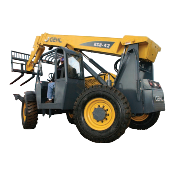
- Page 1 RS6-42 RS8-42 Form No. 913218 Revision C RS8-44 Telescopic Handlers © 2007 Gehl Company • All Rights Reserved. • Printed in USA Courtesy of CraneMarket.com...
- Page 2 Indicator and Operation Symbols Read Operator’s Parking Brake Brake Failure Safety Alert Turn Signals Hazard Flasher Manual Ignition Off Ignition ON Engine Start Hydraulic Oil Horn Engine Oil Pressure Volume Full Volume Half Full Volume Empty Battery Fuel Transmission Temperature Engine Coolant Starting Aid Wiper/Washer...
-
Page 3: Table Of Contents
Warranty ........Inside Back Cover IDENTIFICATION INFORMATION Write your Gehl Telescopic Handler Model and serial numbers below. Refer to these numbers when inquiring about parts or service from your Gehl dealer. MODEL NO. SERIAL NO. -
Page 4: Introduction
A storage pocket in the back of the seat is provided for storing the Operator’s Manual. After using the manual, please return it to the pocket and keep it with the unit at all times! If this machine is resold, GEHL Company rec- ommends that this manual be given to the new owner. - Page 5 Identification Boom Angle Operator’s Dash Indicators Rear Boom Tilt Lift Indicator Station and Controls Cylinder Access Cylinder Quick-attach Operator’s Rear Lights and Outriggers System Seat Backup Alarm Access Hydraulic Extend Cylinder Frame Leveling Access Covers Slave Reservoir Telescopic (inside boom) Cylinder Cylinder (under cover)
-
Page 6: Specifications
Maximum lift capacity: Type: Dana Powershift T12000 RS8-42 23,350 lbs. (10,591 kg) RS8-44 8000 lbs. (3628 kg) Speeds: 3 fwd / 3 rev RS6-42 22,000 lbs. (9,979 kg) RS8-42 8000 lbs. (3628 kg) Torque converter: Instrumentation RS6-42 6600 lbs. (2994 kg) -
Page 7: Checklists
Chapter 3 CHECKLISTS PRE-DELIVERY I acknowledge that pre-delivery procedures were performed The following Checklist is an important reminder of inspec- on this unit as outlined above. tions that MUST be made before delivering the Telescopic Handler to the customer. Check off each item after pre- scribed action is taken. - Page 8 INTENTIONALLY BLANK (To be removed as Dealer’s file copy) 913218/CP0307 PRINTED IN U.S.A. Courtesy of CraneMarket.com...
- Page 9 Chapter 3 CHECKLISTS PRE-DELIVERY I acknowledge that pre-delivery procedures were performed The following Checklist is an important reminder of inspec- on this unit as outlined above. tions that MUST be made before delivering the Telescopic Handler to the customer. Check off each item after pre- scribed action is taken.
-
Page 10: Safety
Chapter 4 SAFETY The above Safety Alert Symbol means ATTENTION! Gehl Company ALWAYS takes the operator’s safety ALWAYS BE ALERT! YOUR SAFETY IS into consideration when designing its machinery, and INVOLVED! It stresses an attitude of “Heads Up for guards exposed moving parts for his/her protection. - Page 11 SAFETY Additional Safety Reminders WARNING User/operator safety practices, as established by industry standards, are included in this Operator’s Manual and intended to promote safe operation of U.S. OSHA regulations require employers in the machine. These guidelines do not, of course, general industry and the construction, ship- preclude the use of good judgment, care and com- yard and cargo-handling industries (excepting...
- Page 12 SAFETY Walk around the machine and warn all personnel DO NOT exceed the machine’s rated operating who may be servicing the machine or who are in capacity for the type of attachment tool being used. the machine path prior to starting. DO NOT start DO NOT allow minors or any unqualified person- until all personnel are clearly away from the nel to operate or be near the machine unless prop-...
- Page 13 ALWAYS wear safety glasses with side shields To ensure continued safe operation, replace dam- when striking metal against metal. In addition, it is aged or worn-out parts with genuine GEHL service recommended that a softer (chip-resistant) materi- parts before using this equipment.
- Page 14 Safety Guards and Warning Devices 2. The platform must be securely attached to the car- riage or forks, and the carriage securely attached to This machine is fitted with a Roll-Over Protective the boom. Structure (ROPS) and Falling Object Protective 3.
-
Page 15: Work Platform Design Requirements
20. The combined weight of the platform, personnel and load must not exceed one-third of the materi- Electrical Connection al-handling capacity of the forklift. 21. Platform personnel must maintain firm footing on the platform floor, unless secured by harness and Remote lanyard. - Page 16 9. Restraining means such as a guardrail or a means for securing personnel such as a body harness and lanyard. A guardrail or similar structure shall have a nominal height to the platform floor of 42 inches (1066 mm) around its upper periphery and include a midrail.
- Page 17 SAFETY L65926 L70307 L70306 101506 L70307 L70306 L65926 101506 PRINTED IN U.S.A. 913218/CP0307 Courtesy of CraneMarket.com...
- Page 18 SAFETY L65927 L70305 L65933 L65927 L70305 L65927 L65927 L65928 100359 L65932 L65932 913218/CP0307 PRINTED IN U.S.A. Courtesy of CraneMarket.com...
- Page 19 SAFETY L65932 L65928 100359 L65927 L70305 L65933 PRINTED IN U.S.A. 913218/CP0307 Courtesy of CraneMarket.com...
- Page 20 SAFETY L65926 L65928 L65927 L65927 L66613 913218/CP0307 PRINTED IN U.S.A. Courtesy of CraneMarket.com...
- Page 21 SAFETY L65928 L65927 L65926 L66613 PRINTED IN U.S.A. 913218/CP0307 Courtesy of CraneMarket.com...
- Page 22 SAFETY PWP Safety Decals L71555 L71554 L71700 L71555 L71554 102969 L71554 L71700 102969 913218/CP0307 PRINTED IN U.S.A. Courtesy of CraneMarket.com...
-
Page 23: Indicators And Controls
BEFORE operating it. This GEHL machine is designed and intended to be used ONLY with WARNING a GEHL Company attachment tool, or a GEHL Company approved accessory or referral Read and thoroughly understand all safety attachment tool. GEHL Company cannot be... - Page 24 DASH PANEL AREA Coolant Temperature Gauge: The upper right gauge in the instrument Key Switch OFF: When the key is verti- panel, it indicates the temperature of cal in the keyswitch, power from the bat- the engine coolant. Under normal tery is disconnected to the control and conditions, this gauge should indicate instrument panel electrical circuits.
- Page 25 Failure in one of the brake systems does not affect the Engine Fault Override Shutdown operation of the other system. However, the MANDA- Switch: Pressing the override shutdown switch will override an engine shutdown TORY SAFETY SHUTDOWN PROCEDURE (p. 8) should be followed and any required repairs made signal.
- Page 26 Middle Row Switches Cold Starting: This switch activates the injection of an ether agent for faster engine Switches have graphic symbols to indicate position starts in cold weather. and response. The following mode descriptions start Heater Controls with the first switch from the left. NOTE: Some switches are optional and may not be on machine.
- Page 27 MANDATORY SAFETY SHUTDOWN PROCEDURE (page 8). Throttle Pedal: This is right-foot operated and con- DO NOT attempt repairs. Call your Gehl dealer trols the engine RPM to match increased power for assistance. requirements. Pushing down on the pedal increases The truss boom and winch attachment tools engine speed;...
- Page 28 Two Joystick Configuation Outrigger Controls: The outriggers are an option used to provide greater stability in specific applica- Frame Level and Outrigger Auxilliary tions. The left lever controls the left outrigger. The Attachment Joystick Controls Hydraulics right lever controls the right outrigger. Move the levers Control forward to lower the outriggers.
- Page 29 To extend the boom, move the joystick right. To retract trols the auxiliary hydraulics, and the left pilot valve the boom, move the joystick left. To raise the boom, controls the attachment tilt function. On the attachment move the joystick rearward. To lower the boom, move tilt pilot valve, the left knob controls the attachment the joystick forward.
-
Page 30: Service And Safety Features
Outrigger Controls: The outriggers are an option Engine Oil Level: Dipstick is located on the right side used to provide greater stability in specific applica- of the middle section of the main hood. tions. The left lever controls the left outrigger. The Coolant Level: Coolant can be checked and added right lever controls the right outrigger. -
Page 31: Side View Mirror
Side View Mirror: Located on the front outside corner ATTACHMENT TOOLS of the fuel tank. It provides the operator with a view to Gehl offers a versatile range of attachment tools to the rear of the machine. meet various lifting and material handling applications. -
Page 32: Operation And Adjustments
Chapter 6 OPERATION AND ADJUSTMENTS GENERAL INFORMATION BEFORE STARTING ENGINE Before starting the engine and running the machine, CAUTION refer to the Indicators and Controls chapter and become familiar with the various operating controls, indicators and safety features. BEFORE starting the engine and operating the Telescopic Handler, review and comply with STARTING THE ENGINE ALL safety recommendations in the SAFETY... - Page 33 20 F (-7 C) or engine RPM while the machine is in motion. lower. See your Gehl dealer for recommended heater. DO NOT overspeed the engine when down-shifting. If prevailing temperature is 40 F (4...
- Page 34 The Telescopic Handler boom nose will accept Quick- To detach attachment tool, proceed as follows: attach System Gehl attachment tools. The Quick-attach System has a quick-release hookup and locking mech- 1. Raise the boom slightly and extend it 2 to 3 feet anism for mounting framing-type or masonry-type (600 to 900 mm) for better visibility.
- Page 35 Modifications, alterations to, or use of attach- ment tools NOT authorized by GEHL (or the If the machine is found to be in need of repair or in any manufacturer) in writing can void warranty...
-
Page 36: Traffic Flow Patterns
Operate the travel controls gradually and smoothly 4. DO NOT travel across a side hill that exceeds 18% when starting, stopping, turning and reversing direc- or 10° grade. Regardless of the terrain or position tion. of the wheels, the FRAME MUST BE LEVEL, as indicated by the level indicator on the Grade and Slope Precautions ROPS/FOPS cross member. - Page 37 Operation of the hydraulic system depends on engine speed and the distance the controls are moved. When operating these controls it is important to develop a technique called “feathering.” Feathering the control means you start the desired motion by moving the con- Stop Raise Load Lower Load...
- Page 38 NEVER leave the operator’s station without with the position extension markers on the operator first lowering the attachment tool to the side of the intermediate boom section. ground. Then set the parking brake, place con- The following example illustrates proper use of the trols in neutral, shut off engine and remove load zone charts for the Telescopic Handler: the key.
- Page 39 Load Elevation and Placement WARNING For ground level load placement, be sure the area under the load and around the machine is clear of NEVER exceed the rated operating capacity of equipment and personnel. Lower the load to the the Telescopic Handler as shown on the load ground, tilt the forks to the horizontal position, and zone charts.
- Page 40 5. Secure the lanyard from the body harness to the PWP or the boom. Each person in the PWP should have a body harness with a lanyard attached to the PWP. Elevating Personnel Retaining This Telescopic Handler is primarily intended for use as a material handler.
-
Page 41: Suspended Loads
Call your Gehl dealer. lized. And, of course, the load must never be posi- tioned over personnel at any time. -
Page 42: Theft Deterrents
2. The ramps MUST be firmly attached to the truck or trailer bed with NO step between the bed and GEHL has recorded all component part numbers and the ramps. serial numbers. Users should take as many of the fol-... - Page 43 5. Report any theft to your dealer and insurance com- pany. Provide the model and all serial numbers. Request your dealer to forward this information to Gehl Company. PRINTED IN U.S.A. 913218/CP0307 Courtesy of CraneMarket.com...
- Page 44 INTENTIONALLY BLANK 913218/CP0307 PRINTED IN U.S.A. Courtesy of CraneMarket.com...
-
Page 45: Lubrication
Chapter 7 LUBRICATION GENERAL INFORMATION Hydraulic System Reservoir Use Mobil DTE 15M, or an equivalent that WARNING contains anti-rust, anti-foam and anti-oxida- tion additives and conforms to ISO VG46. Capacity: NEVER lubricate or service this unit when any 47 Gallons (178 liters) part of the machine is in motion. - Page 46 REPLACEMENT FILTER CHART FUEL ENGINE HYDRAULIC TRANS. ENGINE TYPE FILTER FILTER FILTER STRAINER JOHN DEERE w/ Mechanical Throttle L120037 L98978 102173 L97489 L49327 L99184 JOHN DEERE w/ Electronic Throttle L120037 102174 102173 L97489 L49327 L99184 GREASING --- CHASSIS AREA --- 9.
- Page 47 Grease Fittings Locations PRINTED IN U.S.A. 913218/CP0307 Courtesy of CraneMarket.com...
-
Page 48: Service And Storage
BEFORE resuming machine operation. The following areas of internal components service replacement and operating adjustments should only be by (or under the direction of) an authorized GEHL Telescopic Handler dealer. NOTE: All service routines, with the exception of... - Page 49 OPERATOR SERVICES Before removing one of these valves, you ARE REQUIRED to call your GEHL dealer or Some of the operator-related services will require GEHL Service Department. Failure to do so access to components located inside the superstructure, may result in serious injury or death.
- Page 50 Replace any cracked or damaged parts. hydraulic, battery or fuel systems; all contain Use only genuine GEHL parts for service. highly flammable liquids or explosive gases, which can cause an explosion or fire if ignited. Use care not to damage machined and polished sur- faces.
- Page 51 With the machine on level ground, remove the radiator When installing tires on the machine, be sure that all cap. If the coolant level is below the filler neck, add a tires are of the same size and style. ALWAYS replace low-silicate ethylene glycol base coolant mixed with tires with the same size furnished as original equip- quality water and supplemental coolant additives...
- Page 52 OPERATION AND CONDITION NOT USE the machine until the cause has Are any decals missing or damaged? Are all guards, been corrected. Contact your dealer (or Gehl shields and covers in place? Do all controls function Company) for service information and parts.
-
Page 53: 250 Hours
Lockout Tests Service Every 50 Hours or Weekly To test the transmission and joystick control lockout logic: Refer to the Lubrication chapter of this manual for weekly grease fitting locations and other related 1. Shift transmission into “F” (Forward) and increase details. - Page 54 See illustration. Remove the oil check plug. Oil should NOTE: For proper replacement procedures refer flow from the hole. If low, remove the oil fill plug and to the engine manual for your machine. add oil until it flows from the check hole. Replace the plug, wait 10 to 15 minutes and repeat the fill proce- WARNING dure.
- Page 55 Battery acid is harmful on contact with skin or CHANGING ENGINE OIL AND FILTER fabrics. If acid spills, follow these firstaid tips: Change the engine oil and filter using the following 1. IMMEDIATELY remove any clothing on procedure: which acid spills. 1.
- Page 56 DO NOT attempt to jump-start the machine if CHECKING AND TORQUING BOOM LEAF the battery is frozen, because this may cause CHAINS it to rupture or explode. Inspect the leaf chains for wear and proper tension. Two of the chains are on the top front of the boom. A IMPORTANT: BE SURE that the jumper battery third chain is accessible from inside the rear of the...
- Page 57 transmission oil. Shut down the engine. Access to filter Rear Inner and drain plug is from underneath the machine. Shim Proceed as follows: 1. Remove the drain plug and drain old oil. Replace the drain plug. IMPORTANT: DO NOT discharge oil onto ground.
- Page 58 IMPORTANT: Fill the cooling system with a low-silicate ethylene glycol base coolant mixed a single dry element. Later machines used dual dry ele- with quality water and supplemental coolant addi- ments. Refer to the following illustrations. tives (SCAs) suitable for heavy-duty diesel engines.
- Page 59 filter element and an inner (secondary) filter element. Inner Element An air filter restriction indicator for monitoring the NOTE: Replace the inner element only if it is vis- condition of the elements is located on the front of the ibly dirty or if the outer element has been replaced air cleaner.
- Page 60 Axle Planetary Hubs Test ports under rear access cover. The hubs have one plug each used for draining and fill- ing (see illustration). Before conducting any test port pressure checks, check Plug in drain the engine rpm. Engine speed must be 800 rpm at idle position.
- Page 61 1. Remove the drain plug and drain out all used oil. 3. Change engine oil as outlined in the Service and Wash or blow off all particles collected on the Storage chapter of this manual. magnetic drain plug. 4. Apply grease to all exposed hydraulic cylinder rod IMPORTANT: DO NOT discharge oil onto ground.
- Page 62 PWP System switch. the end of the boom. System level sensor Contact your Gehl dealer for unplugged or faulty. assistance. PWP System mode lamp flash- es when switch is turned “OFF.” PWP System is not de-activated.
-
Page 63: Decal Locations
RS8-44 Telescopic Handler with PWP 102967 RS8-42 Telescopic Handler without PWP 102966 RS8-42 Telescopic Handler with PWP 102810 RS6-42 Telescopic Handler without PWP 102811 RS6-42 Telescopic Handler with PWP NOTE: Decals may be purchased in kits or indi- vidually. PRINTED IN U.S.A. - Page 64 DECAL LOCATIONS - FRAME AND BOOM REF. DESCRIPTION RS8-44 RS8-42 RS6-42 PART NO. PART NO. PART NO. DANGER - HANDS OUT L70305 L70305 L70305 WARNING - PINCH POINT L65927 L65927 L65927 WARNING - JUMP START L65933 L65933 L65933 GEHL, 5.00”...
- Page 65 DECAL LOCATIONS - FRAME AND BOOM REF. DESCRIPTION RS8-44 RS8-42 RS6-42 PART NO. PART NO. PART NO. DANGER - HANDS OUT L70305 L70305 L70305 WARNING - PINCH POINT L65927 L65927 L65927 GEHL, 8.00” 102025 102025 102025 HYDRAULIC OIL FILL 137632...
- Page 66 Dual Joystick Control Tri-function Joystick Control DECAL LOCATIONS - OPERATOR STATION REF. DESCRIPTION RS8-44 RS8-42 RS6-42 PART NO. PART NO. PART NO. WARNING-TILT HAZZARD/GENERAL OPERATOR L70306 L70306 L70306 WARNING - CARRY LOAD LOW L65926 L65926 L65926 F-N-R SHIFT L68295 L68295 L68295 STEERING WHEEL 2.0”...
- Page 67 DECAL LOCATIONS - PWP EQUIPPED UNITS REF. DESCRIPTION RS8-44 RS8-42 RS6-42 PART NO. PART NO. PART NO. WARNING-PERSONNEL LIFT L71554 L71554 L71554 WARNING-WORK PLATFORM RULES L71555 L71555 L71555 PERSONNEL LIFT SAFETY RULES L71700 L71700 L71700 PWP LOAD CHART 102788 102924...
-
Page 68: Maintenance
Chapter 10 MAINTENANCE This Maintenance Interval Chart was developed to match the Service and Storage chapter of this manual. Detailed information on each Service Procedure may be found in the Service and Storage chapter. A Maintenance Log fol- lows the Maintenance Interval Chart for recording the maintenance procedures performed. Recording the 10 Hour (or Daily) service intervals would be impractical and is therefore not recommended. - Page 69 MAINTENANCE INTERVAL CHART (CONT.) SERVICE PROCEDURE Every 250 Every 1000 Every 2000 Hours (or Hours (or Hours (or Quarterly) Yearly) Two Years) Checking and Torquing Boom Leaf Chains Checking Boom Slide Pads Wear and Clearance Checking Personnel Work Platform System Changing Transmission Oil and Filter Changing Radiator Coolant Changing Hydraulic Return Filter Element...
- Page 70 MAINTENANCE LOG Date Hours Service Procedure 913218/CP0307 PRINTED IN U.S.A. Courtesy of CraneMarket.com...
- Page 71 MAINTENANCE LOG Date Hours Service Procedure PRINTED IN U.S.A. 913218/CP0307 Courtesy of CraneMarket.com...
-
Page 72: Hydraulic Schematics
Hydraulic Schematic w/o PWP with Dual Joystick Control (continued on next page) “A” “B” 913218/CP0307 PRINTED IN U.S.A. Courtesy of CraneMarket.com... - Page 73 Hydraulic Schematic w/o PWP with Dual Joystick Control (continued from previous page) “A” “B” PRINTED IN U.S.A. 913218/CP0307 Courtesy of CraneMarket.com...
- Page 74 Hydraulic Schematic with PWP with Dual Joystick Control (continued on next page) “A” “B” “C” 913218/CP0307 PRINTED IN U.S.A. Courtesy of CraneMarket.com...
- Page 75 Hydraulic Schematic with PWP with Dual Joystick Control (continued from previous page) “A” “B” “C” PRINTED IN U.S.A. 913218/CP0307 Courtesy of CraneMarket.com...
- Page 76 Hydraulic Schematic w/o PWP with Tri-Function Joystick Control (continued on next page) “A” “B” 913218/CP0307 PRINTED IN U.S.A. Courtesy of CraneMarket.com...
- Page 77 Hydraulic Schematic w/o PWP with Tri-Function Joystick Control (continued from previous page) “A” “B” PRINTED IN U.S.A. 913218/CP0307 Courtesy of CraneMarket.com...
- Page 78 Hydraulic Schematic with PWP with Tri-Function Joystick Control (continued on next page) “A” “B” “C” 913218/CP0307 PRINTED IN U.S.A. Courtesy of CraneMarket.com...
- Page 79 Hydraulic Schematic with PWP with Tri-Function Joystick Control (continued from previous page) “A” “B” “C” PRINTED IN U.S.A. 913218/CP0307 Courtesy of CraneMarket.com...
-
Page 80: Electrical Schematics
Electrical Schematic with Dual Joystick Control (continued on next page) “A” “B” “C” “D” “E” “F” “G” “H” “I” “J” “K” “L” “M” “N” 913218/CP0307 PRINTED IN U.S.A. Courtesy of CraneMarket.com... - Page 81 Electrical Schematic with Dual Joystick Control (continued on next page) “A” “B” “C” “D” “E” “F” “G” “H” “I” “J” “K” “L” “M” “N” PRINTED IN U.S.A. 913218/CP0307 Courtesy of CraneMarket.com...
- Page 82 Electrical Schematic with Tri-Function Joystick Control (continued on next page) “A” “B” “C” “D” “E” “F” “G” “H” “I” “J” “K” “L” “M” “N” 913218/CP0307 PRINTED IN U.S.A. Courtesy of CraneMarket.com...
- Page 83 Electrical Schematic with Tri-Function Joystick Control (continued on next page) “A” “B” “C” “D” “E” “F” “G” “H” “I” “J” “K” “L” “M” “N” PRINTED IN U.S.A. 913218/CP0307 Courtesy of CraneMarket.com...
-
Page 84: Load Zone Charts
RS8-44 Load Zone Charts Decal 102795 Decal 102797 Standard Carriage 1 Cu. Yd. Bucket Decal 102796 Decal 102798 Rotating Carriage 15 Ft. Truss Boom 913218/CP0307 PRINTED IN U.S.A. Courtesy of CraneMarket.com... - Page 85 RS8-44 Load Zone Charts Decal 102806 Decal 102799 Swing Carriage Winch Boom Decal 103770 Decal 102788 180° Swing Carriage PRINTED IN U.S.A. 913218/CP0307 Courtesy of CraneMarket.com...
- Page 86 RS8-42 Load Zone Charts Decal 102918 Decal 102920 Standard Carriage 1 Cu. Yd. Bucket Decal 102919 Decal 102921 Rotating Carriage 15 Ft. Truss Boom 913218/BP0706 PRINTED IN U.S.A. Courtesy of CraneMarket.com...
- Page 87 RS8-42 Load Zone Charts Decal 102923 Decal 102922 Swing Carriage Winch Boom Decal 102924 Decal 103769 180° Swing Carriage PRINTED IN U.S.A. 913218/CP0307 Courtesy of CraneMarket.com...
- Page 88 RS6-42 Load Zone Charts Decal 102790 Decal 102792 Standard Carriage 1 Cu. Yd. Bucket Decal 102791 Decal 102793 Rotating Carriage 12 Ft. Truss Boom 913218/CP0307 PRINTED IN U.S.A. Courtesy of CraneMarket.com...
- Page 89 RS6-42 Load Zone Charts Decal 103768 Decal 102794 180° Swing Carriage Winch Boom Decal 102787 PRINTED IN U.S.A. 913218/CP0307 Courtesy of CraneMarket.com...
-
Page 90: Standard Hardware Torque Data
Torque Specifications Use these torque values when tightening GEHL hardware (excluding: locknuts and self-tapping, thread-forming and metal screws) unless otherwise specified. Grade 2 Grade 5 Grade 8 Unified National Thread Lubed Lubed Lubed 8-32 8-36 10-24 10-32 1/4-20 1/4-28 5/16-18... -
Page 91: Index
Index Floor and Seat .......25 Other Indicators ......28 Access To Components Chart . - Page 92 Grease Fittings Oils - See Lubrication Locations ........44 Operation Types Of Grease .
- Page 93 Seat, operator’s ....... .25 Service and safety Features ..... . .28 Service Intervals Daily .
- Page 94 NOTES 913218/CP0307 PRINTED IN U.S.A. Courtesy of CraneMarket.com...
- Page 95 Original Retail Purchaser to be free from defects in material and workmanship for a period of twelve (12) months from the Warranty Start Date. GEHL WARRANTY SERVICE INCLUDES: Genuine Gehl parts and labor costs required to repair or replace equipment at the selling dealer's business location. GEHL MAKES NO REPRESENTATIONS OR WARRANTIES OF ANY KIND,...
- Page 96 Battery posts, terminals and related accessories contain lead and lead com- pounds, chemicals known to the State of California to cause cancer and birth defects or other reproductive harm. Wash hands after handling battery. GEHL Company 143 Water Street, P.O. Box 179, West Bend, WI 53095-0179 U.S.A. www.gehl.com 913218/CP0307 ©...
Need help?
Do you have a question about the RS6-42 and is the answer not in the manual?
Questions and answers