Table of Contents
Advertisement
Quick Links
reServer Industrial
Introduction
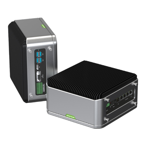
reServer Industrial-series offers fanless compact AI-enabled NVR server built with NVIDIA advanced AI
embedded systems: Nvidia Jetson Orin™ NX/Orin™ Nano delivering AI performance from 20 TOPS to
100 TOPS. With pre-installed OS system, PoE interfaces, rich extension modules, industrial peripherals,
Hybrid network connectivity, thermal management, expandable storage combined with decades of
Seeed's hardware expertise, reServer Industrial Jetson is ready to help you accelerate and scale the
next-gen AI products emerging diverse AI scenarios.
Packing List
1* reServer Industrial
1* DIN Rail Bracket
10* Bracket Screw
1* 16-Pin Terminal Block for DIO
1* 24V/5A Power Adapter(without power cord)
1* 2-Pin Terminal Block Power Connector
Reference Guide
Fanless compact AI-enabled NVR server
Wider temperature support -20 ~ 60°C with 0.7m/s airflow
Multi-stream processing
5* GbE RJ45(4 for 802.3af PSE); support multiple 4K streams
with real-time processing complex tasks
Expandable storage
2 Drive Bays to support 2.5" SATA HDD/SSD; 1* M.2 2280
M key socket for NVMe SSD
Design for industrial interfaces
1* COM(RS232/422/485); 4* DI/DO; 1* CAN; 4* USB3.1;
1* TPM2.0 (Module optional)
Hybrid connectivity
Support 5G/4G/LTE/LoRaWAN
1* Nano SIM card slot
(Module optional) with
®
1
Advertisement
Table of Contents

Related Manuals for SeeedStudio reServer Industrial J4012

Summary of Contents for SeeedStudio reServer Industrial J4012
-
Page 1: Introduction
reServer Industrial Reference Guide Fanless compact AI-enabled NVR server Wider temperature support -20 ~ 60°C with 0.7m/s airflow Multi-stream processing 5* GbE RJ45(4 for 802.3af PSE); support multiple 4K streams with real-time processing complex tasks Expandable storage 2 Drive Bays to support 2.5" SATA HDD/SSD; 1* M.2 2280 M key socket for NVMe SSD Design for industrial interfaces 1* COM(RS232/422/485);... -
Page 2: Table Of Contents
Table of Contents Introduction Part list Hardware Overview Specifications Block Diagram Pin Definitions Front View DC in - J17 USB 2.0DEVICE - J18 USB 2.0 DEBUG - J19 Nano SIM card slot - J6 RECOVERY Button - SW2 GbE connector LAN0 - J14 4* LAN GbE PoE OUT - J10 Back View... -
Page 3: Hardware Overview
Hardware Overview 4*DI; 4*DO; HDMI DC In 1* LAN 4* LAN GbE 2 Drive Bays to support 2.5" SATA HDD/SSD 1*CAN 12-36V RJ45 GbE PoE OUT State LED Power LED 4* USB3.1 Recovery Button RS232/RS422/RS485 USB2.0 Debug SIM Nano USB2.0 Device Specifications reServer Industrial reServer Industrial ... -
Page 4: Block Diagram
Block Diagram... -
Page 5: Pin Definitions
Pin Definitions Front View DC In 1* LAN 4* LAN GbE 12-36V RJ45 GbE PoE OUT State LED Power LED Recovery Button USB2.0 Debug SIM Nano USB2.0 Device DC in - J17 12V-36V, 10A current limit. After plugging in the power supply, the POWER LED lights up. LED Name Descriptions Status... -
Page 6: Usb 2.0 Debug - J19
USB 2.0 DEBUG - J19 Pin # Module Pin Name Module Pin # Schematic Signal Usage/Description Type/Dir Default A4/B9 GPIO00 USB0_VBUS_DET* VBUS Supply Power A9/B4 (USB_VBUS_EN0) – – CC1_1 – – – – CC2_1 – – USB0_D_N USB0_AP_N USB 2.0 #0 Data Bidir USB0_D_P USB0_AP_P... -
Page 7: Recovery Button - Sw2
RECOVERY Button - SW2 Recovery button: FORCE_RECOVERY, press the RECOVERY button SW2 to enter the recovery mode, which allows you to flash the system of the core board. GbE connector LAN LED connection speed color indicators: Active & Link (Left LED) Speed (Right LED) 10 Mbps Yellow (Blinking) - Page 8 4* LAN GbE PoE OUT - J10 Pin # Schematic Signal Usage/Description Type/Dir LAN 1 - J10-1 MXA_P Gigabit Ethernet MDI 4+ Bidir MXA_N Gigabit Ethernet MDI 4– Bidir MXB_P Gigabit Ethernet MDI 3+ Bidir MXB_N Gigabit Ethernet MDI 3– Bidir MXC_P Gigabit Ethernet MDI 2+...
- Page 9 Pin # Schematic Signal Usage/Description Type/Dir LAN 3 - J10-3 MXA_P Gigabit Ethernet MDI 4+ Bidir MXA_N Gigabit Ethernet MDI 4– Bidir MXB_P Gigabit Ethernet MDI 3+ Bidir MXB_N Gigabit Ethernet MDI 3– Bidir MXC_P Gigabit Ethernet MDI 2+ Bidir MXC_N Gigabit Ethernet MDI 2–...
-
Page 10: Back View
Back View 4*DI; 4*DO; HDMI 1*CAN 4* USB3.1 RS232/RS422/RS485 DI/DO - J2 Type Label Name Schematic Module Pin BGA Number GPIO V/A Limits Note DI_1_GPIO01 PQ.05 12V Digital Input, ground signal DI_2_GPIO09 211 PAC.06 Input needs tobe connected to DI_3_GPIO11 PQ.06 GND_DI (Pin2/4/6) DI_4_GPIO13 228... -
Page 11: Com 232/422/485 - J1
COM 232/422/485 - J1 MODE 000/100 010/110 Pin # RS232 RS422 RS485 TXD- Data- TXD+ Data+ RXD+ RXD- Note: 1.Default mode is RS485. 2.Toggle the switch(SW3) for mode switching after power off to avoid damage to the device. 3.RS232 comes with flow control. -
Page 12: Mode Selection Instructions
Mode selection instructions Toggle the switch(SW3) for switching the mode of COM RS232/RS422/RS485 (DB9 J1). MODE_0 MODE_1 MODE_2 Mode Status RS-422 Full Duplex 1T/1R RS-422 Pure RS-232 3T/5R RS-232 RS-485 Half Duplex 1T/1R RS-485 ,TX ENABLE Low Active RS-485 Half Duplex 1T/1R RS-485 ,TX ENABLE High Active 1T/1R RS-422 with termination RS-422 Full Duplex... -
Page 13: Hdmi Port - J16
HDMI Port - J16 Pin # Module Pin Name Module Pin # Schematic Signal Usage/Description Type/Dir DP1_TXD0 (HDMI_TXD2)_P HDMI_TXD2_CON_P HDMI Transmit Data 2+ Output – – Ground Ground DP1_TXD0 (HDMI_TXD2)_N HDMI_TXD2_ CON_N HDMI Transmit Data 2– Output DP1_TXD1 (HDMI_TXD1)_P HDMI_TXD1_ CON_P HDMI Transmit Data 1+ Output –... -
Page 14: Usb3.1 Type-A X2 - J3
USB3.1 TYPE-A x2 - J3 Pin # Module Pin Name1 Module Pin # Schematic Signal Usage/Description Type/Dir2 USB 3.1 Type A – – – VBUS Supply Power USB1_D_N USB2_A_N USB 2.0 #3 Data Bidir USB1_D_P USB2_A_P from hub – – Ground Ground USBSS_RX_N... -
Page 15: Usb3.1 Type-A X2 - J4
USB3.1 TYPE-A x2 - J4 Pin # Module Pin Name1 Module Pin # Schematic Signal Usage/Description Type/Dir2 USB 3.1 Type A – – – VBUS Supply Power USB1_D_N USB2_A_N USB 2.0 #3 Data Bidir USB1_D_P USB2_A_P from hub – – Ground Ground USBSS_RX_N... -
Page 16: Carrier Board
Carrier board USB2.0 Device 4* LAN GbE PoE OUT 1* LAN RJ45 GbE USB2.0 Debug Recovery State LED Button Power LED DC In 12-36V SATA Data Connector SATA Power Connector M.2 Key M Mini PCIe Control and UART Header TPM Header DIP Switches 2-Pin RTC Connect RTC Socket... -
Page 17: Control And Uart Header - J8
Control and UART Header - J8 Net Name Net Name SIM_MUX_SEL USB_MUX_SEL MCU_USB_BOOT MCU_RST AUTO_ON_DIS BMCU_ACOK PWR_BTN* MCU_UART1_TX MCU_UART1_RX UART2_TXD_3V3 3V3_MCU UART2_RXD_3V3 DIP Switches - SW3 Toggle the switch(SW3) for switching the mode of COM RS232/RS422/RS485 (DB9 J1). RTC-Pin Header - J12 Pin # Module Pin Name... -
Page 18: Led
LED2: M.2 Key B LED3: Mini PCIe LED4: HDD1 LED5:HDD2 M.2 Key M - J21 Module Pin Module Type/Dir Module Pin Type/Dir Usage/Description Usage/Description Name Pin # Default Name Default – – Ground Ground – – Main 3.3V Supply Power PCIE0_RX3_N 155 PCIe IF #0 Lane 3 Receive Input... -
Page 19: Tpm Header - J11
TPM Header - J11 Schematic Signal Schematic Signal VDD_TPM SPI0_IRQ_LS SPI0_RST_LS VDD_TPM SPI0_CS0_LS SPI0_SCK_LS SPI0_MISO_LS PI0_MOSI_LS Note: Support SPI interface TPM module, test with TPM2.0 Module with infineon SLB9670 (module not included) Mini PCIe - J5 Pin Module Pin Module Schematic Type/Dir ... -
Page 20: Key B - J6
M.2 Key B - J6 Pin Module Schematic Type/Dir Pin Module Pin Module Schematic Type/Dir Module Pin Name Pin # Signal/Description Default Name Pin # Signal/Description Default – – – – VDD_3V3_SYS Power – – Ground – – VDD_3V3_SYS Power – – Ground GPIO10 M2B_POWER_OFF Output USB2_D_P M2B_PCIe_HSD4_P... -
Page 21: Sata
SATA - J27, J30 SATA Data Connector PCIe to 2x SATA Bridge PCIE3 x1 SATA x2 JMB582 Pin # Schematic Signal Usage/Description Type/Dir2 SATA PORT 0 – Ground Ground S_TXP0 Input S_TXN0 Ground Ground S_RXN0 Output S_RXP0 Ground Ground – Ground Ground –... -
Page 22: Accessories Information
FAN Header Pin # Module Pin Name Module Pin # Schematic Signal – – – – GPIO08 (SDMMC_CD) FAN_TACH GPIO14 (PWM) FAN_PWM Note: 1.Whether the fan is self-starting or starts only when it reaches the temperature can be set by yourself. 2.Connect 4Pin 5V fan, fan speed can be controlled, and the speed can be detected. -
Page 23: Flexible Mounting
Flexible mounting Desk 4*Screw - PM4.0*6.0mm 4*Screw - PM4.0*6.0mm VESA 2*Screw - 120° - KM3.0*5.0mm DIN rail... -
Page 24: Certifications
Certifications More information Please check our wiki to learn more about this device and if you have any questions, feel free to reach out to our Forum and Discord community. Scan for more information Wiki Forum Discord For more information, you can also refer to NVIDIA official Jetson Download Center...
Need help?
Do you have a question about the reServer Industrial J4012 and is the answer not in the manual?
Questions and answers