Table of Contents
Advertisement
Quick Links
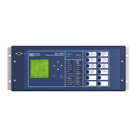
SEL-487E-5 Transformer
Protection Relay
Transformer Protection Relay With
Sampled Values or TiDL Technology
Key Features and Benefits
The SEL-487E-5 Transformer Protection Relay With Sampled Values or TiDL
ential protection for transformer applications with as many as five three-phase restraint current inputs. Use the three
independent restricted earth fault (REF) elements for sensitive ground-fault detection in grounded wye-transformer
applications. Detect turn-to-turn winding faults for as little as two percent of the total transformer winding with the neg-
ative-sequence differential element. Apply the two three-phase voltage inputs for over- and undervoltage, frequency, and
volts/hertz protection. Use distance elements to provide transmission line protection or backup transformer protection.
Make any overcurrent element directional using voltage polarized directional elements as torque control inputs to the
overcurrent elements. Monitor and protect critical substation assets with comprehensive breaker wear and transformer
thermal and through-fault monitoring. Perform bay control functions for as many as 5 breakers and 20 disconnect
switches by using the built-in system mimic diagrams.
➤
High-Speed Differential Protection. A two-stage slope adapts automatically to external fault conditions, providing
fast, sensitive, dependable, and secure differential protection, even for CT saturation and heavily distorted waveforms.
Two independent differential zones are available, one of which supports additional features that accommodate
transformer differential protection.
➤
Inrush and Overexcitation Detection. Combined harmonic blocking and restraint features provide maximum
security during transformer magnetizing inrush conditions. Waveshape-based inrush detection addresses inrush
conditions that contain low second and fourth harmonic content.
➤
Turn-to-Turn Winding Fault Protection. Innovative negative-sequence differential elements provide transformer
windings protection from as little as two percent turn-to-turn winding faults.
➤
Restricted Earth Fault Protection. Three independent REF elements provide sensitive protection for faults close
to the winding neutral in grounded wye-connected transformers.
➤
Combined Overcurrent. Configurations exist for a wide variety of transformer applications. Use the combined
overcurrent elements for transformers connected to ring-bus or breaker and one-half systems. This feature
mathematically sums two terminal current inputs to form a single operating quantity.
Schweitzer Engineering Laboratories, Inc.
®
Technology provides three-phase differ-
SEL-487E Data Sheet
Advertisement
Table of Contents

Related Manuals for Sel SEL-487E-5


Summary of Contents for Sel SEL-487E-5
- Page 1 Sampled Values or TiDL Technology Key Features and Benefits ® The SEL-487E-5 Transformer Protection Relay With Sampled Values or TiDL Technology provides three-phase differ- ential protection for transformer applications with as many as five three-phase restraint current inputs. Use the three independent restricted earth fault (REF) elements for sensitive ground-fault detection in grounded wye-transformer applications.
- Page 2 Alarm contacts provide notification of substation battery voltage problems (as many as two independent battery monitors in some SEL-400 series relays) even if voltage is low only during trip or close operations. ➤...
- Page 3 ➤ TiDL Relay. The TiDL relay can receive current and voltage information from as many as eight SEL-TMUs (TiDL Merging Units) over direct point-to-point fiber-optic connections. The TiDL relay automatically synchronizes data collection, alleviating the need or impact of an external clock on protection.
-
Page 4: Functional Overview
Access (Port 5E) Five-port Ethernet card ordering option depicted. Figure 1 SEL-487E-5 SV Subscriber or TiDL Relay Functional Overview The SEL-487E subscribes to data streams that are pub- lished by merging units, such as the SEL-421-7 SV Pub- Process Bus... -
Page 5: Protection Features
To the relay uses filtered and unfiltered (instantaneous) ana- detect these destructive internal faults, the SEL-487E uses a log quantities in two separate algorithms to form the dif- sensitive negative-sequence current differential element. -
Page 6: Out-Of-Step Detection
Figure 6 Mho Characteristics 24U102 (150,22) Out-of-Step Detection 24U103 (200,14) The SEL-487E supports out-of-step detection by using timers and blinders that are set outside any of the distance Volts/Hertz (%) elements. A power swing is declared when an impedance 24U101 (110,33) locus travels through the blinders slower than a preset time. -
Page 7: Synchronism Check
MAX = Maximum magnitude A-, B-, C-phase currents program the relay to supervise circuit breaker closing. In addition to the selectable operate quantity, the 51S ele- ment time-delay and pickup level inputs are SEL OGIC Current Unbalance Elements programmable settings. This flexibility allows these inputs... - Page 8 The SEL-487E-5 SV Subscriber can be used in applica- tion, while maintaining sensitivity for internal faults. tions with as many as five three-phase current inputs. For Waveshape-based inrush detection addresses inrush con- the application shown in Figure 7, the SEL-487E sub-...
- Page 9 In the SV version of the application a process bus network switch. The same network switch shown in Figure 9, the SEL-487E-5 SV Subscriber Relay communicates GOOSE messaging and time-synchro- subscribes to a total of five IEC 61850 9-2 SV streams nizes the system by using a PTP time source.
-
Page 10: Distance Protection
SEL-TMU, and the SEL-TMU publishes these current four zones of phase and ground distance protection, and voltage values to the SEL-487E-5 TiDL relay over a using mho or quadrilateral characteristics. You can use fiber-optic connection by using SEL T-protocol. The... - Page 11 A single SEL-487E can provide full feeder functionality of six single function feeder relays thereby reducing the device count within the system. Figure 12 shows a TiDL system that can be used for this application; however, an IEC 61850 9-2 sys- tem is also supported.
-
Page 12: Additional Features
Bay Control Figure 13 and Figure 14 show close-up views of the front panel of the SEL-487E. The front panel includes a 128 x The SEL-487E provides dynamic bay one-line diagrams on 128 pixel, 3" x 3" LCD screen; LED target indicators; and... - Page 13 BUSNAM1 BUSNAM2 Figure 15–Figure 18 are examples of some of the select- able one-line diagrams in the SEL-487E. Select the one- line diagram from the Bay settings. Additional settings 6 ANALOGS for defining labels and analog quantities are also found in I:99999.9 A...
-
Page 14: Alarm Points
Figure 19 Screens for Circuit Breaker Selection Rack-Type Breakers Mosaics slide-in label set is included with the SEL-487E. You can use templates supplied with the relay or hand label sup- plied blank labels and print label sets from a printer. -
Page 15: Communications Features
Figure 21 Sample Display Points Screen points to show circuit breaker information and current Communications Features See Specifications on page 25 for specific supported protocols. IEC 61850 or To Remote SEL Relay Front Port Local DNP LAN/WAN Using M Communications... -
Page 16: Sntp Time Synchronization
Configured IED Description (CID) file. Use popular Telnet applications for easy terminal com- munications with SEL relays and other devices. Transfer data at high speeds for fast file uploads. The Ethernet card communicates using FTP applications for easy and fast file transfers. - Page 17 Figure 24 shows two relays with SEL-2815 Fiber-Optic remote analog outputs to virtually any analog quantity Transceivers that use M communications. IRRORED available in the relay. You can also use SEL OGIC communications can operate simultane- IRRORED math variables to develop custom analog quantities ously on any two serial ports.
- Page 18 Outstation relay summary event reports, and settings groups. IEEE C37.118 Phasor measurement protocol. SEL protocol for exchanging digital and analog information among SEL relays and for use as low-speed termi- IRRORED nal connection. IEC 61850 Ethernet-based international standard for interoperability between intelligent devices in a substation.
-
Page 19: Metering And Monitoring
Assign inputs to suit your functions allow superior flexibility. OGIC application, logically combine selected bay elements for various control functions, and assign outputs to your logic functions. Table 3 SEL Control Equation Operators OGIC Operator Type Operators Comments... - Page 20 Each relay provides event reports for analysis with soft- Oscillography and Event Reporting ® ware such as SEL-5601-2 Event Soft- SYNCHRO ware. With Event, you can display SYNCHRO...
-
Page 21: Event Summary
This is a The relay measures and reports the substation battery concise description of an event that includes the follow- voltage for up to two battery systems. The SEL-411L, ing information: SEL-421, SEL-451 support two battery monitors while ➤... -
Page 22: Through-Fault Event Monitor
Transformer thermal monitoring for mineral-oil immersed peratures. The relay uses hot-spot temperature as a basis transformers is a standard feature in the SEL-487E. Spec- for calculating the insulation aging acceleration factor ify the SEL-487E to provide this capability for monitor- (FAA) and loss-of-life quantities. - Page 23 IN13 IN14 IN15 MONITOR POWER Vdc 1 – – Five-port Ethernet card ordering option depicted. Figure 28 SEL-487E-5 SV Subscriber Relay Rear Panel EIA-232 PORT 5A PORT 5B PORT 5C PORT 5D PORT 5E PORT 3 PORT 2 ACT LNK...
-
Page 24: Models And Options
4U (U is one rack unit—1.75 in or 44.45 mm) ➤ DSS connector type ➢ IEC 61850-9-2LE-compliant SV subscriber relay ➢ SEL TiDL relay with T-Protocol Table 5 Interface Board Information Board Name Inputs Description Outputs Description INT2 Optoisolated, independent, level-sensitive... -
Page 25: Communications Protocols
Interruption: 20 ms at 24 Vdc, 100 ms at 48 Vdc Note: You can order SEL-487E-5 as an SV subscriber relay or as a TiDL relay. per IEC 60255-26:2013 For SV applications, operating times are delayed by the configured channel delay, CH_DLY. - Page 26 18 inputs with shared terminals Wavelength (nm): 1310 (2 groups of 9 inputs with each group Source: sharing one terminal) Connector Type: Min. TX Pwr. (dBm): –24 Max. TX Pwr. (dBm): –14 SEL-487E Data Sheet Schweitzer Engineering Laboratories, Inc.
- Page 27 Rated I/O Voltage: 5 Vdc Part Number: 8130-06, 8130-08, or 8130-10 Operational Voltage Range: 0–8 Vdc Mode: Single 2 .2 Vdc Logic High Threshold: Wavelength (nm): 1550 0.8 Vdc Logic Low Threshold: Schweitzer Engineering Laboratories, Inc. SEL-487E Data Sheet...
-
Page 28: Type Tests
1000 A/m 1 to 3 Seconds; 50/60 Hz IRIG-B, Digital Inputs Note: 50G1P 0.05 (ESS = N, 1, 2) ±5.0 kV: Standard Contact Outputs, 50G1P 0.1 (ESS = 3, 4) Power Supply Battery Monitors +5.0 kV: Hybrid Contact Outputs SEL-487E Data Sheet Schweitzer Engineering Laboratories, Inc. -
Page 29: Reporting Functions
1 A nominal ±5% ±0.02 A Storage: 100 summaries 5 A nominal ±5% ±0.10 A Breaker History Time-Delay Accuracy: ±0.1% plus ±0.125 cycle (differential Storage: 128 histories element) ±0.1% plus ±0.25 cycle (distance element) Schweitzer Engineering Laboratories, Inc. SEL-487E Data Sheet... - Page 30 Maximum Operating Time: 1.75 cycles at 90% of reach and SIR = 1 Zones 1—4 Impedance Reach Quadrilateral Reactance Reach OFF, 0.05 to 64 secondary, 0.01 steps 5 A Model: OFF, 0.25 to 320 secondary, 0.01 steps 1 A Model: SEL-487E Data Sheet Schweitzer Engineering Laboratories, Inc.
- Page 31 3I0 5 A Nominal: ±5% of setting, ±0.10 A ±0.05 secondary Accuracy: 1 A Nominal: ±5% of setting, ±0.10 A Transient Overreach: +5% of set reach Max. Delay: 1.75 cycles Schweitzer Engineering Laboratories, Inc. SEL-487E Data Sheet...
-
Page 32: Metering Accuracy
0.50–50 A, 0.01-A steps Currents 1 A Nominal: 0.10–10.0 A, 0.01-A steps Phase Current Magnitude 5 A Model: ±0.2% plus ±4 mA (2.5–15 A sec) 1 A Model: ±0.2% plus ±0.8 mA (0.5–3.0 A sec) SEL-487E Data Sheet Schweitzer Engineering Laboratories, Inc. - Page 33 Optic Transceiver Monitor Ambient or Other Temperatures PT 100, NI 100, NI 120, and CU 10 RTD-Types Supported, Field Selectable As long as 500 m Fiber-Optic Cable to SEL-2600 Series RTD Module Synchrophasor Number of Synchrophasor Data Streams: Number of Synchrophasors for Each Stream:...
-
Page 34: Technical Support
Technical Support We appreciate your interest in SEL products and services. If you have questions or comments, please contact us at: Schweitzer Engineering Laboratories, Inc. 2350 NE Hopkins Court Pullman, WA 99163-5603 U.S.A. Tel: +1.509.338.3838 Fax: +1.509.332.7990 Internet: selinc.com/support Email: info@selinc.com SEL-487E Data Sheet Schweitzer Engineering Laboratories, Inc. - Page 35 Notes Schweitzer Engineering Laboratories, Inc. SEL-487E Data Sheet...
- Page 36 All brand or product names appearing in this document are the trademark or registered trademark of their respective holders. No SEL trademarks may be used without written Tel: +1.509.332.1890 • Fax: +1.509.332.7990 permission. SEL products appearing in this document may be covered by U.S. and Foreign selinc.com • info@selinc.com patents.
Need help?
Do you have a question about the SEL-487E-5 and is the answer not in the manual?
Questions and answers