Table of Contents
Advertisement
Quick Links
SERVICE
AIR CONDITIONER
AC026FBRDEH
AC035FBRDEH
AC052FBRDEH
AC071FBRDEH
AC026FCADEH
AC035FCADEH
AC052FCADEH
Refer to the service manual in the GSPN(see the rear cover) for the more information.
SPLIT-TYPE AIR CONDITIONER
Model :
AC026FBRDEH AC026FCADEH
AC035FBRDEH AC035FCADEH
AC052FBRDEH AC052FCADEH
AC071FBRDEH AC071FCADEH
Model Code :
AC026FBRDEH /EU AC026FCADEH/EU
AC035FBRDEH/EU AC035FCADEH/EU
AC052FBRDEH/EU AC052FCADEH/EU
AC071FBRDEH/EU AC071FCADEH/EU
Manual
1. Precautions
2. Product Specifications
3. Disassembly and Reassembly
4. Troubleshooting
5. PCB Diagram and Parts List
6. Wiring Diagram
7. Schematic Diagram
8. Reference Sheet
AC071FCADEH
CONTENTS
Advertisement
Table of Contents
Troubleshooting

Related Manuals for Samsung AC026FBRDEH


Summary of Contents for Samsung AC026FBRDEH
- Page 1 SPLIT-TYPE AIR CONDITIONER Model : AC026FBRDEH AC026FCADEH AC035FBRDEH AC035FCADEH AC052FBRDEH AC052FCADEH AC071FBRDEH AC071FCADEH Model Code : AC026FBRDEH /EU AC026FCADEH/EU AC035FBRDEH/EU AC035FCADEH/EU AC052FBRDEH/EU AC052FCADEH/EU AC071FBRDEH/EU AC071FCADEH/EU SERVICE Manual AIR CONDITIONER CONTENTS 1. Precautions 2. Product Specifications 3. Disassembly and Reassembly 4. Troubleshooting...
- Page 2 China china.samsungportal.com © Samsung Electronics Co., Ltd. Nov. 2012. This Service Manual is a property of Samsung Electronics Co., Ltd. Printed in China. Any unauthorized use of Manual can be punished under applicable Code No. DB98-32705A(1) International and/or domestic law.
-
Page 3: Table Of Contents
6-1 Indoor Unit ............................6-2 Outdoor Unit ............................. 17. Schematic Diagram ........................7-1 Indoor Unit ............................7-2 Outdoor Unit ............................. 8. Reference Sheet ..........................8-1 Index for Model Name ........................8-2 Refrigerating Cycle Diagram ................................................8-3 Pressure Graph Samsung Electronics... -
Page 4: Precautions
– There is a danger of electric shock. ■ In case the product will not be in use for a long time, the battery of remote control should be kept sepa- rately. – Leakage of inside fluid can cause break down of remote control. Samsung Electronics... -
Page 5: Disposing Of The Unit
2) Release the valve caps on High and Low pressure side. 3) Use L wrench to close the valve on the high pressure side. 4) Approximately 2 minutes after, close the valve on the low pressure side. 5) Stop operation of the air conditioner. 6) Disconnect the pipes. Samsung Electronics... -
Page 6: Product Specifications
Catechin, extracted from the green tea, is contained in the filter and deactivates captured bacteria and unpleasant odors. ■ Silver Nano Evaporator ■ Deodorizing Filter Activated carbon is incorporated in the filter, efficiently absorbing cigarette smoke, pet odors, and other unpleasant smells, replacing them with clean, refreshing air. ■ Anti-Bacterial Cross Fan Samsung Electronics... -
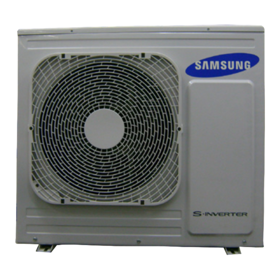
Page 7: Specifications Of Product
2-2 The Specifications of Product AC026FBRDEH/EU AC035FBRDEH/EU AC052FBRDEH/EU ITEM AC026FBADEH/EU AC035FBADEH/EU AC052FBADEH/EU Indoor Unit Outdoor Unit IMAGE Remote Controller Power Product 1Φ, 220-240V/50Hz 1Φ, 220-240V/50Hz 1Φ, 220-240V/50Hz Indoor L x H x D 820*285*205 820*285*205 1065*230*298 Outdoor L x H x D... - Page 8 In case of strongest air Indoor unit blow sound power (Cooling/Heating) In case of strongest air Outdoor unit blow Refrigerant(R410A) 1,800 Liquid 6.35 Connecting Pipe 15.88 Additional Refrigerant (R410A) Standard Extension length(Total) Extension length(Elevation) Product Option 019077-1562AC-274750-370010 Option Code Installation Option 020000-100000-200000-300000 Samsung Electronics...
-
Page 9: Accessory And Option Specifications
2-3 Accessory and Option Specifications Item Descriptions Code-No. Q'TY Remark Assy Remote DB97-17846A Installation Plate DB90-02738A Indoor Unit Owner’s Manual DB68-03440A Installation Manual DB68-03442A Installation Manual DB68-03464A DB67- Outdoor Drain Plug 00477A(026/035/052) Unit DB67-20011A(060) Rubber Leg DB73-20134A Samsung Electronics... -
Page 10: Disassembly And Reassembly
3. Disassembly and Reassembly Necessary Tools ■ Item Remark +SCREW DRIVER MONKEY SPANNER Samsung Electronics... -
Page 11: Indoor Unit
FRONT.(use + Screw Driver) 4) Loosen connector wire(white) and detach the temperature sensor wire. 5) To detach the FRONT-PANEL the main frame, unfasten 2 screw at the bottom.(use + Screw Driver) 6) Take off the FRONT-PANEL,lifting up the bottom. Samsung Electronics... - Page 12 TRAY-DRAIN towards you. CONTROL IN 1) Unfasten the earth screw.(use + Screw Driver) 2) Detach COVER-CONTROL from the CASECONTROL. 3) Detach the temperature sensor. 4) Loosen MOTOR Wire. 5) Take off the CASE-CONTROL from the main frame. Samsung Electronics...
- Page 13 1) Unfasten the screw. 2) Cut the cable tie. 3) Loosen the terminal block wires. Caution: The terminal is locking type. So, when you separate terminals, pull pressing the button. Button Samsung Electronics...
- Page 14 6) Loosen Main Power connector. Caution: When you separate the connector, pull pressing the locking button. 7) Loosen the Thermistor wire connector. Caution: When you separate the connector, pull pressing the locking button. 8) Loosen the Relay connector(Red,White). Samsung Electronics...
- Page 15 1) Unfasten the screw at the right side. (use + Screw Driver) 2) Unfasten the screw at the left side. (use + Screw Driver) 3) Detach the HOLDER PIPE. 4) Take off the EVAPORATOR from the main frame. Samsung Electronics...
- Page 16 2) unfasten the 3 points screws in the CASE- CONTROL, and then detach the CASE. (use + Screw Driver) 3) unfasten the screw a little.(use + Screw Driver) 4) Lift up the evaporator slightly and pull the CROSS-FAN to the left side. Samsung Electronics...
-
Page 17: Outdoor Unit
3-2 Outdoor Unit ■ AC071FCADEH Parts Procedure Remark Common Work 1) Loosen 1 fixing screw of the Cover-Control and detach the Cover Control. 2) Loosen each 7 fixing screws and detach the Cabinet Upper. Samsung Electronics... - Page 18 Parts Procedure Remark 3) Loosen 2 screws fixed to assemble Control Box with Cabinet-Side RH. 4) Loosen fixing screws and detach the Cabinet-Side RH. 5) Loosen 2 screws fixed on the Guide Condenser. Samsung Electronics...
- Page 19 Parts Procedure Remark 6) Loosen fixing screws of the Cabinet Front. 3-10 Samsung Electronics...
- Page 20 2) Detach the Fan Propeller. 3) Loosen 4 fixing screws to detach the Motor. 4) Disconnect the wire between ASS'Y Control Out and Motor. 5) Loosen 2 fixing bolts and detach the Bracket Motor. Samsung Electronics 3-11...
- Page 21 2) Loosen fixing screw on both sides. 3) Disassemble the pipes in both inlet and outlet with welding torch. 4) Detach the Heat Exchanger. 5) Loosen 4 bolts fixed to assemble Valve Service with Bracket Valve like the picture on the right side. 3-12 Samsung Electronics...
- Page 22 Procedure Remark Compressor 1) Loosen the fixing nut and detach the Compressor Lead Wire. 2) Disassemble the Felt Compressor Sound. 3) Loosen the 3 bolts at the bottom of Compressor like the picture on the right side. Samsung Electronics 3-13...
- Page 23 1) loosen 1 pcs screw of cover control,and detach it. 2) loosen 5 pcs screws on both right and left cabniet side edges and to detach the cover-top 3) Loosen 7 screwsfixed to disassemble cabi-front , and detach it. 3-14 Samsung Electronics...
- Page 24 Parts Procedure Remark common work 4) loosen 7 screws to disassemble the cabi- right ,and detach it. 5) loosen 2 screws to disassemble steel-bar. 6) loosen 3 screws to disassemble cabi-left. Samsung Electronics 3-15...
- Page 25 Remark fan&motor 1) loosen 1 screw as indication and detached the fan. 2) loosen 4 pcs motor screws and disconnect the wire betwwen assy control out and motor. 3) loosen 2 pcs bracket-motor screw and detach it. 3-16 Samsung Electronics...
- Page 26 Heat exchanger 1) Release the refrigerant at first 2) Looosen fixing screw on both side. 3) disaessembly the pipes in both inlet and outlet with welding torch. 4) detach the heat exchanger. Samsung Electronics 3-17...
- Page 27 Parts Procedure Remark compressor 1) disconnect the compressor lead wire . 2)disassembly the felt comp sound. loosen the 3 bolts at the bottom of 3-18 Samsung Electronics...
-
Page 28: Troubleshooting
For example : SEG2, 3 SEG4, 5 SEG6, 8 SEG9, 10 SEG11, 12 SEG 14, 15 SEG 16, 17 SEG 18, 20 SEG 21, 22 SEG23, 24. On(SEG1~12) Off(SEG13~24) SEG1 SEG2 SEG3 SEG4 SEG5 SEG6 SEG7 SEG8 SEG9 SEG10 SEG11 SEG12 SEG13 SEG14 SEG15 SEG16 SEG17 SEG18 SEG19 SEG20 SEG21 SEG22 SEG23 SEG24 Samsung Electronics... - Page 29 11. Setting SEG14, SEG15 option Press Low Fan button( ) to enter SEG14 value. ∨ Press High Fan button( ) to enter SEG15 value. ∧ Each time you press the button, will be selected in rotation. … SEG14 SEG15 Samsung Electronics...
- Page 30 Step 5. Check operation 1. Reset the indoor unit by pressing the RESET button of indoor unit or outdoor unit. 2. Take the batteries out of the remote controller and insert them again and then press the operation button. Samsung Electronics...
- Page 31 Example) If you want to set as "MAIN : 3, CHANNEL : 1, RMC : B", SEG1 SEG2 SEG3 SEG4 SEG5 SEG6 SEG7 SEG8 SEG9 SEG10 SEG11 SEG12 assign option codes except SEG 1, 7 which are page options. Samsung Electronics...
- Page 32 Indication Details Indication Details Indication Details Indication Details Indication Details Indication Details Thermo Disuse Disuse Use of buzzer 1000 Hour Indication ON/OFF Details Control Operation Non use 2000 of buzzer Hour Control Samsung Electronics...
- Page 33 : 2000hr", SEG1 SEG2 SEG3 SEG4 SEG5 SEG6 SEG7 SEG8 SEG9 SEG10 SEG11 SEG12 SEG13 SEG14 SEG15 SEG16 SEG17 SEG18 SEG19 SEG20 SEG21 SEG22 SEG23 SEG24 assign option codes except SEG 1, 7, 13, 19 which are page options. Samsung Electronics...
- Page 34 PAGE MODE mode you want an option SEG an option SEG value to change you will change you will change Indication 4-1-6 Option code for each model Model OPTION CODE AC026FBRDEH/EU 019057-17622C-271A23-370010 AC035FBRDEH/EU 019057-17624E-272328-370010 AC052FBRDEH/EU 019077-17621D-27343C-370010 AC071FBRDEH/EU 019077-1562AC-274750-370010 Samsung Electronics...
-
Page 35: Things To Check Before Diagnosis
Error of heat exchanger sensor in the indoor unit Indoor fan motor mal function EEPROM error EEPROM option error Flickering X Off ● If you turn off the air conditioner when the LED is flickering, the LED is also turned off. Samsung Electronics... -
Page 36: Troubleshooting For Outdoor Unit
PFC Overload Error Check Outdoor Inverter PBA E500 IPM is over heated. Check Outdoor Inverter PBA E554 GAS Leak error Check indoor and outdoor unit model E556 Capacity miss match between indoor and outdoor Check indoor and outdoor unit model Samsung Electronics... - Page 37 Operation Off protection of the compressor control error Check the input power Outdoor unit [Inverter] Total current error/PFC over Check the coolant charging status Operation Off protection current error Check the normal operation of outdoor fan control error 4-10 Samsung Electronics...
-
Page 38: Wired Remote Controller
Wired remote Normal operation error COM2 terminal of the indoor unit controller error Wired remote controller COM2 Wired remote Check that Com1, Com2 setting DIP switch is set to Com2 Normal operation option setting error controller error Samsung Electronics 4-11... -
Page 39: Fault Diagnosis By Symptom
Temp. (°C) (KΩ) 5.800 6.900 At that time, does the resistance value deviate from the 8.300 temp. table beside? 10.00 12.10 Indoor temp. sensor 14.70 self-defect (replacement) 18.00 Resume operation after replacing PCB 22.00 28.30 33.90 42.30 4-12 Samsung Electronics... -
Page 40: Indoor Heat Exchange Temperature Sensor (Open/Short)
(KΩ) 5.800 6.900 At that time, does the 8.300 resistance value deviate from the temperature 10.00 table beside? 12.10 Indoor Heat Exchange temp. 14.70 sensor 18.00 self-defect (replacement) Resume operation after replacing PCB 22.00 28.30 33.90 42.30 Samsung Electronics 4-13... -
Page 41: Indoor Fan Error
Is Motor connector disconnected from the PCB? Resume operation after connecting to the connector PCB Is there any clogging (binding) of foreign substances in the MotorFan? Resume operation after removing the foreign substances. Resume operation after replacing PCB 4-14 Samsung Electronics... -
Page 42: Communication Error After Completion Of Tracking
PCB and connector After reconnecting the communication line that links outdoor and indoor units, remove communication connector in the indoor PCB. If communication does not work during operation, replace PCB of the indoor unit. Good defect +0.7V -0.7V Samsung Electronics 4-15... -
Page 43: Eeprom Circuit Part Defect
(necessary component missing in EEPROM circuit part/ damage/ soldering defect) Resume operation after repairing it according to P8-2 circuit diagram’s EEPROM part, P6~6-10 component list. If problem occurs during re-operation, replace PCB Resume operation after replacing PCB 4-16 Samsung Electronics... -
Page 44: When Outdoor Units Cannot Be Turned On
Main PCB DC265V~DC357V? Is reactor 1 and 2 (reactor connection wire) properly connected Connect the connection wire of the reactor to the reactor? Power ok? Replace outdoor unit PCB for Outdoor MICOM defect. Finish Samsung Electronics 4-17... -
Page 45: Dc Link And Over/Lower Voltage Error
1. Inspection items 1) Is compressor operating properly? 2) Is there a connection between input power and power? 2. Inspection order Is EMI PCB and Turn off the power then reconnect Inverter PCB connected properly? Replace PCB 4-18 Samsung Electronics... -
Page 46: Ipm And Over Current Error
Are the values for R418 current sensing resistance within Resistance replacement 19mΩ-21mΩ? Is resistance value of the different compressor phases Compressor replacement (UV, V W, WU) less than 2Ω? Continue (continued on the back) Samsung Electronics 4-19... - Page 47 Turn off the power then temperature sensor and measurement value reconnect the cable normal? Is the connection Turn off the power then cable between the compressor and PCB correct the sensor location or replace it properly connected? Replace PCB 4-20 Samsung Electronics...
-
Page 48: Compressor Starting Error, Compressor Locking Error, Compressor Revolving Error
Compressor phases (U↔V, V ↔W, W ↔U) less than 2Ω? Is the resistance Replace the Compressor between the Compressor body and chassis Maga Ω? Is the Compressor connection line properly connected to the Check the connection line Compressor? Replace the outdoor unit’s PCB Samsung Electronics 4-21... -
Page 49: Outdoor Temperature Sensor Error
Replace PCB after turning off the power the voltage of both sides. Do they indicate DC1V~DC4V? Is there a Replace temperature sensor after turning short circuit or defective contact in off the power the sensor wires? Replace PCB after turning off the power 4-22 Samsung Electronics... -
Page 50: Emission Temperature Sensor Error
Replace PCB after turning off the power the voltage of both sides. Do they indicate DC1V~DC4V? Is there a Replace temperature sensor after turning short circuit or defective contact in off the power the sensor wires? Replace PCB after turning off the power Samsung Electronics 4-23... -
Page 51: Cond Temperature Sensor Error
Replace PCB after turning off the power the voltage of both sides. Do they indicate DC1V~DC4V? Is there a Replace temperature sensor after turning short circuit or defective contact in off the power the sensor wires? Replace PCB after turning off the power 4-24 Samsung Electronics... -
Page 52: Communication Error Between Indoor/Outdoor Units (1Min.)
Replace PCB of the outdoor unit block F1–F2, less than DC5V? after turning off. When measuring F1–F2, the outdoor terminal block, if the voltage varies (communicates) below DC5V, the connection status of the connection line is normal. Samsung Electronics 4-25... -
Page 53: Outdoor Fan Error
No.1 and No. 3 pin of the the voltage of the no.13 pin of the outdoor unit CN01 between 1V~5V? the IC01 (MICOM)? Replace the main PCB of the Defective MICOM outdoor unit Continue (continued on the back) 4-26 Samsung Electronics... - Page 54 CN71 Is there any change in the voltage of the Replace the main PCB of the no.13 pin of the IC01 outdoor unit (MICOM)? Replace the main PCB of the Replace BLDC fan motor outdoor unit Samsung Electronics 4-27...
-
Page 55: Discharge Current Error/ Pfc Over-Current Error
Is the outdoor unit installed correctly? Reinstall after removing obstacle Is indoor unit installed correctly? Reinstall after removing obstacle Replace the compressor Is the compressor operating normally? Open valves Is the service valve open completely? Replace PCB 4-28 Samsung Electronics... -
Page 56: Gas Leakage Error
Compressor phases (U↔V, V ↔W, W ↔U) less than 2Ω? Is the service valve open completely? Open valves Is the indoor EVA sensor connected properly? Reconnect the sensor connector ace th Is refrigerant filled? Replace the outdoor unit’s PCB Samsung Electronics 4-29... -
Page 57: Other
Check the connection between input power and the power is okay then replace the PCB 5. AC zero Crossing signal out error Check the connection between input power and the power is okay then replace the PCB 6. Inconsistent volume Check the option code of the indoor unit. 4-30 Samsung Electronics... -
Page 58: Pcb Diagram And Parts List
5. PCB Diagram and Parts List 5-1 PCB Diagram 5-1-1 Indoor Unit Samsung Electronics... - Page 59 ⑤ DISPLAY CONNECTOR SMW200-10 NTR ⑥ DISPLAY CONNECTOR SMAW250A-03 RED ⑦ PC DOWNLOADCONNECTOR SMW200-10 BLK ⑧ S NE T CONNECTOR SMW200-04 NTR ⑨ AS-PRO DOWNLOAD CONNECTOR SMAW200A-07 WHT ⑩ DISPLAY CONNE CTORS MW200-05 NTR ⑪ DOWNLOAD-INV CONNECTOR S MW200-10 RED Samsung Electronics...
-
Page 60: Outdoor Unit
⑥ EEV-A CONNECTOR SMAW250-06 RED SMW250-06 BLU ⑦ OUT/DIS/COND CONNECTOR SMAW200-10P BLK ⑧ DOWNLOAD-MAIN CONNECTOR ⑨ CENTRAL-CTL CONNECTOR SMW200-05P WHT YW396-06V WHT ⑩ BLDC-FAN CONNECTOR ⑪ DOWNLOAD-INV CONNECTOR SMAW200-10P RED DBT061-3P WHT ⑫ COMP CONNECTOR ⑬ REACTOR CONNECTOR DBT081-2P WHT Samsung Electronics... - Page 61 Outdoor Unit PCB (cont.) ■ Sub PCB (AC071FCADEH) ① 12V POWER CONNECTOR YW396-02V BLU ② MAIN -SUB SIGNAL CONNECTOT SMW250-04 WHT ③ MAIN -SUB SIGNAL CONNECTOT SMW200-15NTR Samsung Electronics...
- Page 62 Outdoor Unit PCB (cont.) ■ SUB PCB (AC026FCADEH/ AC035FCADEH/ AC052FCADEH) ① EVAP THERMISTOR CONNECTOR SMW250-08 WHT ② EEV-B CONNECTOR SMW250-05 YEL ③ DISPLAY-MAIN CONNECTOR SMW200-28 WHT ④ 12V POWER CONNECTOR YW396-02AV BLU Samsung Electronics...
-
Page 63: Wiring Diagram
6. Wiring Diagram 6-1 Indoor Unit Samsung Electronics... -
Page 64: Outdoor Unit
6-2 Outdoor Unit Samsung Electronics... -
Page 65: Schematic Diagram
7-1-1 MAIN PCB POWER SMPS PART STEP MOTOR CONTROL PART ROOM & PIPE IN TEMP SENSOR PART COMMUNICATION PART UP/DOWN&AUTO AGRILLE PART DISPLAY PART CHECK & CONTROL SIGNAL PART This Document can not be used without Samsung's authorization. Samsung Electronics... -
Page 66: Outdoor Unit
7-2 OUtDOOr UNIt PCB 7-2 -1 MAIN PCB ( AC071FCADEH) This Document can not be used without Samsung’s authorization. Samsung Electronics... - Page 67 OUtDOOr UNIt PCB 7-2-2 SUB PCB (rC060DHXEA/ rC071DHXEA/ rC052DHXEH/ rC060DHXEH / AC060FCADEH/ AC071FCADEH ) This Document can not be used without Samsung’s authorization. Samsung Electronics...
- Page 68 OUtDOOr UNIt PCB AC026FCADEH/ AC035FCADEH/ AC052FCADEH) 7-2-3 MAIN PCB (rC026DHXEA /rC035DHXEA /rC052DHXEA / rC026DHXEH/ rC035DHXEH/ This Document can not be used without Samsung’s authorization. Samsung Electronics...
- Page 69 OUtDOOr UNIt PCB AC026FCADEH/ AC035FCADEH/ AC052FCADEH) 7-2-4 SUB PCB (rC026DHXEA /rC035DHXEA /rC052DHXEA / rC026DHXEH/ rC035DHXEH/ This Document can not be used without Samsung’s authorization. Samsung Electronics...
-
Page 70: Reference Sheet
Temp.+MODULE LSP DUCT Non Inv+Side+Tropical Temp DELUXE STANDARD+ RAC-NEO FORTE Non Inv+Top+Tropical Temp STANDARD TROPICAL+MODULE RAC-MALDIVE STANDARD+GENERAL Temp.+NON MODULE CEILING CONSOLE FLOOR MOUNTING ※ "/" can be removed from the buyer card if there are not enough digits. Samsung Electronics... -
Page 71: Refrigerating Cycle Diagram
Using a hex wrench, turn the needle valve counterclockwise to open the valve. It is used for vacuuming, gas drain, refrigerant injection, refrigerant purge, and indoor-outdoor units connection. ■ Accumulator It prevents liquid refrigerant from flowing into the compressor. (If liquid refrigerant enters the compressor, it becomes overloaded) Samsung Electronics... -
Page 72: Pressure Graph
27/19 27/1 21/15 Outdoor Temp.(°C) Heating S Heating 35.0 Indoor (°C) 28/18 27/19 20/15 Outdoor(°C) 30.0 34.3 34.0 30.6 29.8 29.5 26.6 25.0 25.4 25.1 22.6 32/2 28/18 24.2 24.0 21.6 20.0 27/19 27/1 20/15 15.0 Outdoor Temp.(°C) Samsung Electronics...