Dräger PSS 7000 Series Instructions For Use
Self contained breathing apparatus
Hide thumbs
Also See for PSS 7000 Series:
- Reference manual (21 pages) ,
- Instructions for use (5 pages) ,
- Instructions for use (2 pages)
Advertisement
Quick Links
PSS
7000 Series
®
Self contained breathing apparatus with Sentinel 7000
For Your Safety
General safety information for the Dräger PSS® 7000 Series of self-contained breathing
apparatus (SCBA):
Use of this apparatus requires relevant equipment training; observance of this user
instruction (UI); and compliance with national regulations, laws and standards governing
the use of respiratory apparatus.
Use of this apparatus must be only for the purpose specified in this UI, or as confirmed
in writing by Dräger.
Only trained and competent personnel should inspect and service the apparatus at specified
intervals. Records of inspections and servicing are to be maintained in line with NFPA
1852 – Standard on Selection, Care, and Maintenance of Open-Circuit Self-Contained
Breathing Apparatus.
Use of the apparatus should be consistent with NFPA 1500 – Standard on Fire Department
Occupational Safety and Health Program.
The automatic alarm function of the Sentinel 7000 detects movement of the wearer and
movement or vibration to which the wearer may be subjected.
Do not use any form of chemical marking or paint on the equipment.
Dräger recommend that a service contract be obtained from your Dräger branch or agent.
Contact Dräger for details of service contracts and training courses.
Use only original Dräger spare parts and test equipment for service, repair and maintenance.
Notify Dräger if there is component fault or failure.
All approved respiratory equipment shall be selected, fitted, used, and maintained in
accordance with Mine Safety and Health Administration (MSHA), Occupational Safety
and Health Administration (OSHA), and other applicable regulations.
Before occupational use of this respirator a written respiratory protection program must
be implemented meeting all the local government requirements. In the United States
employers must comply with OSHA 29 CFR 1910.134 which includes medical evaluation,
training, and fit testing.
Definitions of Alert Icons
The following alert icons are used throughout this document to provide and highlight
areas of the associated text that require a greater awareness by the user. A definition of
the meaning of each icon is as follows:
This icon indicates additional information on how to avoid inconveniences
i
i
when carrying out the instructions described.
NOTICE
This icon indicates a potentially hazardous situation which, if not avoided,
!
could result in physical injury to the user, or damage to the product. It
CAUTION
may also highlight an alert against unsafe practices.
This icon indicates a potentially hazardous situation which, if not avoided,
!
could result in death or serious injury to the user.
WARNING
This icon indicates an imminently hazardous situation which, if not avoided,
!
could result in death or serious injury to the user.
DANGER
Warranty and Liability Statements
Terms and conditions of warranty for the Dräger PSS® 7000 Series of SCBA and
associated accessories can be found in the original Dräger invoice document, or can be
obtained from Dräger on request.
The Dräger guarantee is void if the original sealing caps on the apparatus are tampered
with, removed or broken
Responsibility for the reliable function of the apparatus transfers to the owner or
operator when it is serviced or repaired by personnel not authorised by Dräger, or when
it is used in a manner not conforming to its intended use.
This device has been tested and complies with the FCC rules. Changes or
!
modifications not expressly approved by the manufacturer will void your authority
to operate this product.
CAUTION
Description and Intended Use
This UI describes the Dräger PSS® 7000 Series of SCBA fitted with the following:
A Dräger Sentinel 7000 electronic monitoring system, with integral personal alert
safety system (PASS).
A Dräger wireless head-up display (HUD) unit.
The Dräger PSS® 7000 is a compact and lightweight apparatus that provides the wearer
with respiratory protection when working in contaminated or oxygen-deficient conditions.
The system can be used as a self-contained system or with an independent air supply
to increase effective operation time. The system is fully compatible with a wide range of
compressed-air cylinders, face masks and lung demand regulators (LDRs).
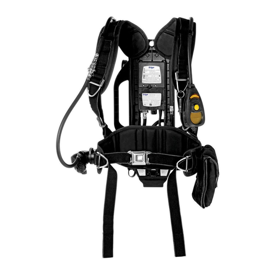
The carrying system has a height-adjustable articulating backplate (6, Fig 1) that provides
improved comfort and ease of use, resulting in increased manoeuvrability and reduced
fatigue. The carbon-composite backplate incorporates a sliding height-adjustable yoke
that has three preset positions. A flexible pivot joint located at the base of the backplate
(in line with the hip of the wearer) moves in response to the twisting and bending of the
wearer, improving the weight distribution and freedom of movement. The system includes
adjustable shoulder straps (2) and waist belt (11).
The Sentinel 7000 electronic monitoring system is a multi-function system that provides
continuous monitoring of the SCBA status including remaining cylinder pressure,
movement of the wearer, main battery condition, end-of-service time (EOST) and PASS.
It provides visual indications of system status and audible and visual alarms in warning
conditions. User control and monitoring of the system is through a user interface (1)
that incorporates switches, LEDs, a liquid crystal display (LCD) display screen and an
alarm sounder. A backlight illuminates the user interface display screen when required.
Additional alarm sounders (5), with warning LEDs top and bottom, are mounted on the
backplate and operate only during PASS alarms. The operating settings are preset and
non-adjustable by the user.
The PASS function of Sentinel 7000 electronic monitoring system is an alarm system
that can be activated manually or automatically. The automatic alarm uses a motion
sensor to detect movement and activate a pre-alarm and main alarm at timed intervals
when no movement is sensed. The manual alarm is activated by a press button on the
user interface. A limitation of the PASS is that it detects movement or vibration to which
the wearer is subjected.
Power supplies include a main battery located in the backplate, a back-up battery
located beneath the pressure module and a HUD battery located in the HUD. The
system is switched on by pressing the buttons on the user interface or by cylinder
pressure felt at a pressure module, with cylinder pressure transmitted to the pressure
module through a high-pressure hose (7). At switch on, a self test is performed and then
the system adopts the active mode where the PASS function is operational.
All variants utilise the same high-performance, first-stage, regulator (9) fitted with an EOST
mechanical whistle (10). The pressure regulator supplies medium-pressure breathing
air to a quick-release coupling (4) via a medium-pressure hose (3). Incorporated in the
first-stage regulator is a rapid intervention crew universal air connection (RIC UAC) (8).
The RIC UAC is a male coupling that allows emergency replenishment of breathing air
to the air cylinder while wearer is breathing from the apparatus.
A wireless HUD unit (refer to instruction no. 3356234) located in the face mask
provides visual indications to the wearer of a number of system conditions. Signals from
the Sentinel 7000 to the HUD are from a pressure transducer/transmitter incorporated
in the pressure module.
PSS
®
is a registered trade mark of Dräger
Technical Data
High-Pressure Connections
The following SCBA high-pressure (HP) connections are available for compressed air
cylinders:
2216 psi connection to CGA 346
4500 psi connection to CGA 347
Quick-connect cylinder coupling (2216 psi or 4500 psi).
Power Supplies
Main battery – 7.5 V
Back-up battery – 3 V
Head-up display battery – 3 V.
RIC UAC Connection
2216 psi or 4500 psi male, quick-release coupling with pressure relief valve (PRV).
LDR to
Connection
Face mask
Dräger push-in connector.
Pressure and Flow Details
Medium pressure – 87 psi to 130 psi
Air flow – In excess of 1000 liters/minute
Air flow at 290 psi – In excess of 500 liters/minute.
EOST Alarms
Activation commencement range (mechanical and electronic):
2216 psi cylinder – 600 psi to 510 psi
4500 psi cylinder – 1215 psi to 1035 psi.
General Information
Batteries
Danger of explosion. Do not change the batteries in an explosive or
!
flammable atmosphere.
WARNING
Do not dispose of batteries in a fire. Batteries must be disposed of in
!
line with local regulations.
WARNING
Do not attempt to recharge any non-rechargeable battery.
!
CAUTION
Battery information:
Main battery – 7.5 V (5 x 1.5 V AA alkaline batteries)
Back-up battery – 3 V (CR123 lithium battery)
HUD battery – 3 V (CR123 lithium battery).
Use only the following approved battery types:
Procell by Duracell LR6 (1.5 V)
Duracell Plus LR6 (1.5 V)
Panasonic CR123AL/1BP (3 V).
Batteries are supplied with the equipment but are not fitted. Dräger
i
i
recommend that the batteries be removed when the system is not used
for long periods as a small amount of discharge still occurs. The normal
NOTICE
operating life of the batteries is dependent on usage time, frequency of
alarms, backlight illumination and ambient temperature.
When the SCBA is in operational use; should the display screen switch off
i
i
and the functionality of the HUD be powered by the back-up battery, then after
use of the SCBA Dräger recommend that the back-up battery is replaced.
NOTICE
The back-up battery will only supply power when the main battery is
i
i
disconnected or discharged. When this occurs, the back-up battery will only
supply power for HUD functions.
NOTICE
Preparation for Use
Equipment configurations for non-CBRN use are detailed in a NIOSH Approval Table
(refer to instruction no. 3356261). Configurations for CBRN use are detailed later in this
instruction (refer to CBRN Use).
Installing the Back-Up Battery
Orientate the SCBA to access the battery compartment.
Unscrew and remove the battery cap (1, Fig 2), using a suitable coin.
Insert the battery, +ve terminal end first, into the battery compartment.
Refit and secure the battery cap. Do not overtighten.
Installing the Main Battery
Inspect the sealing rim around the battery terminals. Ensure that the terminals of the
battery, and the pressure transmitter module, are clean and undamaged.
Lift and turn over the SCBA to access the pressure transmitter module.
Insert the battery pack into the backplate recess. Refer to Figure 3.
Position thumbs on top of the two screws, push down firmly to lock the battery pack.
Refer to Figure 3 and 4.
Whilst pushing down, confirm the two sliding locks move to their locked position
viewed through the two keyholes as illustrated. Refer to Figure 5.
The Sentinel 7000 will emit a single tone and will commence the self-check
sequence (refer to Sentinel 7000 Self Check).
Press and hold the RH and LH buttons of the user interface until the display clears,
then immediately release the buttons.
A battery check is performed during the self-check sequence. If the
i
i
battery voltage is below a preset voltage the backlight will illuminate; the
low battery icon (Fig 6) will be displayed; the Sentinel 7000 will emit a
NOTICE
series of tones for approximately four seconds; and then the display will
switch off. When this occurs replace the battery.
To remove the battery insert and press the two pronged key (supplied
i
i
with the SCBA) into the two keyholes at the base of the battery. This will
open the locking latch allowing the battery to be removed.
NOTICE
Installing the Cylinder
The following instructions are for a screw-on cylinder coupling. Installation
i
i
of a quick-connect cylinder coupling is detailed in a separate UI (refer to
instruction no. 3356260).
NOTICE
Set the carrying-frame backplate to the short (S) position (refer to Adjusting the
Backplate Height).
Inspect and check the following:
The external thread of the cylinder valve port.
The internal thread of the first-stage regulator handwheel.
The O-ring seal in the pressure connector is in position and not damaged.
The bore to the sintered filter in the HP connector of the first-stage regulator is
clean and free from dirt and contamination.
Lay the carrying frame horizontal and fully extend the cylinder strap.
i
Instructions for Use
2
1
D
5
3
9
11
10
1
2
2804
3
2797
4
2798
5
2743
Take care to prevent impact damage as the cylinder valve is aligned with the first-stage
regulator handwheel.
Insert the cylinder (valve end first) through the cylinder strap, to align the cylinder
valve with the handwheel.
Lift the cylinder and backplate into the vertical position (supported on the end of the
cylinder).
Align and fully tighten the handwheel (clockwise). Do not use tools or overtighten.
Place the unit back into the horizontal position.
Take up the slack of the cylinder strap and activate the cam-lock mechanism by
pulling the free end of the strap back over the cylinder (Fig 7).
Secure the strap using the Velcro fastening.
Adjusting the Backplate Height
Lift the SCBA into the vertical position.
Simultaneously press the two spring-loaded buttons (Fig 8) of the locking catch.
Slide the yoke to the required position (short (S), medium (M) or long (L)) and
release the spring-loaded buttons.
Grasp the yoke and the frame and attempt to raise and lower the yoke to confirm
that the locking catch is fully engaged.
Connecting the LDR and HUD
Insert and push the male coupling of the LDR hose into the quick-release coupling
of the SCBA medium-pressure hose until it latches into position. Check the security
of the connection (do not connect the LDR to the face mask at this stage).
Install a serviceable HUD into the face mask (refer to instruction no. 3356234).
3
4
5
6
1
8
7
3775
6
2580
7
2186
8
2006
bar
psi
MPa
9
2191
3356233 (A3-D-P) Page 1 of 4
Advertisement

Subscribe to Our Youtube Channel
Related Manuals for Dräger PSS 7000 Series


Summary of Contents for Dräger PSS 7000 Series
- Page 1 7000 Series ® Instructions for Use Self contained breathing apparatus with Sentinel 7000 For Your Safety Technical Data General safety information for the Dräger PSS® 7000 Series of self-contained breathing High-Pressure Connections apparatus (SCBA): Use of this apparatus requires relevant equipment training; observance of this user The following SCBA high-pressure (HP) connections are available for compressed air instruction (UI);...
- Page 2 7000 Series ® Instructions for Use Self contained breathing apparatus with Sentinel 7000 Pre-Operational Checks Press the front button (2, Fig 15) of the LDR and check that air flow is delivered into the face mask. Press the reset button (1) to stop the air flow. Sentinel 7000 Self Check Close the cylinder valve and breathe normally to empty the system of pressure. ...
- Page 3 7000 Series ® Instructions for Use Self contained breathing apparatus with Sentinel 7000 After Use Carrying harness – Thorough cleaning S – Special or Critical Users’ Instructions Do not immerse pneumatic or electronic components in cleaning Do not remove the SCBA until in a safe area. Do not drop or throw down ...
- Page 4 7000 Series ® Instructions for Use Self contained breathing apparatus with Sentinel 7000 Table 2 Table 3 Equipment servicing Troubleshooting Symptom Fault Remedy Component/ Task After use Every Every year Every System month Face mask air leak O-ring at LDR to face mask connection Renew or lubricate O-ring years Headstraps not tight...
Need help?
Do you have a question about the PSS 7000 Series and is the answer not in the manual?
Questions and answers