Table of Contents
Advertisement
Quick Links
Owner's Manual
Original Instructions
Air Conditioners
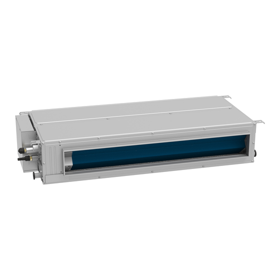
DC Inverter U-match Series Duct Type Unit
Models:
Indoor Unit
GUD35P1/A-S
GUD50P1/A-S
GUD71PH1/A-S
GUD85PH1/A-S
GUD100PH1/A-S GUD100PHS1/A-S
GUD125PH1/A-S GUD125PHS1/A-S
GUD140PH1/A-S GUD140PHS1/A-S
GUD160PH1/A-S GUD160PHS1/A-S
GUD35PS1/A-S
GUD50PS1/A-S
GUD71PHS1/A-S
GUD85PHS1/A-S
Outdoor Unit
GUD35W1/NhA-S
GUD50W1/NhA-S
GUD71W1/NhA-S
GUD85W1/NhA-S
GUD100W1/NhA-S
GUD125W1/NhA-S
GUD140W1/NhA-S
GUD160W1/NhA-X
GUD100W1/NhA-X
GUD125W1/NhA-X
GUD140W1/NhA-X
Advertisement
Table of Contents

Related Manuals for Argo GUD35P1/A-S


Summary of Contents for Argo GUD35P1/A-S
- Page 1 Owner's Manual Original Instructions Air Conditioners DC Inverter U-match Series Duct Type Unit Models: Indoor Unit Outdoor Unit GUD35P1/A-S GUD35PS1/A-S GUD35W1/NhA-S GUD50P1/A-S GUD50PS1/A-S GUD50W1/NhA-S GUD71PH1/A-S GUD71PHS1/A-S GUD71W1/NhA-S GUD85PH1/A-S GUD85PHS1/A-S GUD85W1/NhA-S GUD100PH1/A-S GUD100PHS1/A-S GUD100W1/NhA-S GUD100W1/NhA-X GUD125PH1/A-S GUD125PHS1/A-S GUD125W1/NhA-S GUD125W1/NhA-X GUD140PH1/A-S GUD140PHS1/A-S...
- Page 2 To Users Thank you for selecting Gree product. Please read this instruction manual carefully before installing and using the product, so as to master and correctly use the product. In order to guide you to correctly install and use our product and achieve expected operating effect, we hereby instruct as below: (1) This appliance can be used by children aged from 8 years and above and persons with reduced physical, sensory or mental capabilities or lack of...
- Page 3 Exception Clauses Manufacturer will bear no responsibilities when personal injury or property loss is caused by the following reasons: (1) Damage the product due to improper use or misuse of the product. (2) Alter, change, maintain or use the product with other equipment without abiding by the instruction manual of manufacturer.
-
Page 4: Table Of Contents
Contents 1 Safety Notice (Please be sure to abide them) ....1 2 Installation ................5 2.1 Installation Preparation ............5 2.2 Unit Installation ..............14 2.3 Electrical Installation ............35 2.4 Check after Installation ............46 2.5 Product Operating Range ............ 46 2.6 Test Running ................ -
Page 5: Safety Notice (Please Be Sure To Abide Them)
DC Inverter U-match Series Duct Type Unit 1 Safety Notice (Please be sure to abide them) SPECIAL WARNING: (1) Be sure to comply with national gas regulations. (2) Do not pierce or burn. (3) Do not use means to accelerate the defrosting process or to clean, other than those recommended by the manufacturer. - Page 6 DC Inverter U-match Series Duct Type Unit Please read this operating manual carefully before operating the unit. The air conditioner is charged with inflammable refrigerant R32 (GWP: 675). Before using the air conditioner, please read the instruction manual. Before installing the air conditioner, please read the instruction manual. Before repairing the air conditioner, please read the instruction manual.
- Page 7 DC Inverter U-match Series Duct Type Unit WARNING! (6) Air conditioner should be stored with protective measures against mechanical damage caused by accident. (7) If the installation space for air conditioner pipe is too small, adopt a protective measure to prevent the pipe from physical damage. (8) During installation, use the specialized accessories and components, otherwise water leakage, electric shock or fire hazard may occur.
- Page 8 DC Inverter U-match Series Duct Type Unit WARNING! (24) Do not make the air conditioner wet or electric shock may be lead, ensure that the air conditioner will not be cleaned by water rinsing under any circumstance. (25) When you do not connect the duct, you need to provide an extra protective net to avoid touching the basic insulation.
-
Page 9: Installation
DC Inverter U-match Series Duct Type Unit 2 Installation 2.1 Installation Preparation 2.1.1 Notice on Installation (1) Notice on Refrigerant Concentration before Installation. This air conditioner uses R32 refrigerant. The construction area for installation, operation and storage of the air conditioner must be larger than the minimum construction area. - Page 10 DC Inverter U-match Series Duct Type Unit Ceiling type Wall mounted type Floor standing type Weight Weight Weight Area (m²) Area (m²) Area (m²) (kg) (kg) (kg) 6.54 9.76 87.9 7.38 11.0 99.2 8.27 12.4 9.22 13.8 10.2 15.3 11.3 16.8 12.4 18.5...
- Page 11 DC Inverter U-match Series Duct Type Unit (3) Please use the charging machine specialized for R32 refrigerant before charging, keep the refrigerant tank in an upright position. After charging, stick a label on the air conditioner saying no excessive charging. (4) The following tools will be used: 1) Liquid-level gauge;...
- Page 12 DC Inverter U-match Series Duct Type Unit (8) Indoor unit, power cord, connecting wires and communication cords should be at least 1m from television and radio. This is to prevent image interference or noise (Even at a distance of 1m, a very strong electric wave may still generate noise).
- Page 13 DC Inverter U-match Series Duct Type Unit (1) Indoor Unit GUD35P1/A-S,GUD35PS1/A-S,GUD50P1/A-S,GUD50PS1/A-S, GUD140PH1/A-S,GUD140PHS1/A-S, GUD160PH1/A-S, GUD160PHS1/A-S. GUD71PH1/A-S,GUD71PHS1/A-S,GUD85PH1/A-S,GUD85PHS1/A-S GUD100PH1/A-S,GUD100PHS1/A-S,GUD125PH1/A-S,GUD125PHS1/A-S. Unit: mm Dimensions Model GUD35P1/A-S GUD35PS1/A-S GUD50P1/A-S 1060 1000 GUD50PS1/A-S GUD71PH1/A-S GUD71PHS1/A-S...
- Page 14 DC Inverter U-match Series Duct Type Unit Dimensions Model GUD85PH1/A-S GUD85PHS1/A-S GUD100PH1/A-S 1381 1340 GUD100PHS1/A-S GUD125PH1/A-S 1381 1340 GUD125PHS1/A-S GUD140PH1/A-S 1440 1400 GUD140PHS1/A-S GUD160PH1/A-S 1440 1400 GUD160PHS1/A-S NOTE! Drilling of ceiling opening and installation of air conditioner must be performed by professionals! (2) Outdoor Unit GUD35W1/NhA-S,GUD50W1/NhA-S,GUD71W1/NhA-S, GUD85W1/NhA-S,...
- Page 15 DC Inverter U-match Series Duct Type Unit Unit: mm Dimensions Model GUD35W1/NhA-S GUD50W1/NhA-S GUD71W1/NhA-S GUD85W1/NhA-S GUD100W1/NhA-S 1020 GUD100W1/NhA-X 1020 GUD125W1/NhA-S 1020 GUD125W1/NhA-X 1020 GUD140W1/NhA-S 1020 GUD140W1/NhA-X 1020 GUD160W1/NhA-X 1070 2.1.4 Diagram of Unit Installation Space and Location (1) Diagram of installation space and location for outdoor unit (Notice: for best performance of the outdoor unit, make sure its installation space conforms to the following installation dimensions).
- Page 16 DC Inverter U-match Series Duct Type Unit (mm) A,B,C,E — ≥300 ≥150 ≥150 — ≥1000 — — — — ≥1000 — — — — — ≥1000 ≥1000 <H >H — ≥100 — ≥1000 — >H <H — ≥100 — ≥1000 —...
- Page 17 DC Inverter U-match Series Duct Type Unit (mm) ≤1/2H — ≥300 — ≥2000 ≥1000 <H 1/2H<H ≤H — ≥300 — ≥2500 ≥1000 >H Prohibited B,D,E ≤1/2H — ≥250 — ≥2500 ≥1000 >H 1/2H<H ≤H — ≥300 — ≥2500 ≥1000 >H Prohibited 3) When outdoor units are installed in rows.
-
Page 18: Unit Installation
DC Inverter U-match Series Duct Type Unit 4) When outdoor units are installed one above another. Unit: mm (2) Diagram of installation location and space for indoor unit (Notice: for the best performance of indoor unit, make sure its installation space conforms to the following installation dimensions). - Page 19 DC Inverter U-match Series Duct Type Unit (1) Install the bolts to the ceiling at a place strong enough to hang the unit. Mark the bolt positions from the installation template. With a concrete drill for 12.7mm diameter holes. See the following figure. Unit:mm (2) Insert the anchor bolts into the drilled holes, and drive the pins completely into the anchor bolts with a hammer.
- Page 20 DC Inverter U-match Series Duct Type Unit (4) Pass the unit hangers over the bolts installed to the ceiling and install the unit with the special nut. See the following figure. Unit:mm 2.2.1.2 Leveling After installing the indoor unit, level detection of the unit shall be conducted. Place the unit horizontally and leave the left and right side with a downward slope of 1/100~1/50 in drainage direction, as shown below.
- Page 21 DC Inverter U-match Series Duct Type Unit outdoor unit should be at least 10cm from the installation ground). See the following figures. (5) Plugs and drainage connector are not recommended if there is an electrical heater on the chassis. 2.2.3 Connection Pipe Installation 2.2.3.1 Installation Notice and Requirement on Connection Pipe Installation of Ordinary Nut and Tamperproof box Unfold the connecting pipe and bend the connecting pipe according to the...
- Page 22 Size of Fitting Item Maximum Biggest drop Pipe(inch) pipe length between indoor and Liquid Model outdoor units (m) pipe pipe GUD35P1/A-S Φ3/8 GUD35PS1/A-S Ф1/4 GUD50P1/A-S Φ1/2 GUD50PS1/A-S GUD71PH1/A-S GUD71PHS1/A-S GUD85PH1/A-S GUD85PHS1/A-S GUD100PH1/A-S GUD100PHS1/A-S Φ3/8 Φ5/8...
- Page 23 DC Inverter U-match Series Duct Type Unit When the drop between indoor and outdoor units is larger than 10m, an oil return bend should be added every 6m. The requirement on the adding of oil return bend is as below: (1) Outdoor unit is beneath the indoor unit.
- Page 24 DC Inverter U-match Series Duct Type Unit Dimensions for the making of oil return bend are as follows: A(inch) B(mm) C(mm) Ф3/8 ≥20 ≤150 Ф1/2 ≥26 ≤150 Ф5/8 ≥33 ≤150 2.2.3.2 Pipe Flaring (1) Cut the connection pipe with a pipe cutter. (2) The mouth of connection pipe should face downward.
- Page 25 DC Inverter U-match Series Duct Type Unit (2) Do not bend the pipes in an angle more than 90°. (3) If the pipe is repeatedly bent or extended, it will become hard and difficult to be bent or extended. So do not bend or extend the pipe for more than 3 times.
- Page 26 DC Inverter U-match Series Duct Type Unit Pipe diameter (inch) Tightening torque (N·m) Ф1/4 15-30 Ф3/8 35-40 Ф1/2 45-50 Ф5/8 60-65 Ф3/4 70-75 Ф7/8 80-85 Screw on the flare nut of the flaring connecting pipe on the outdoor unit valve. The method of screwing the flare nut is the same with that for indoor unit.
- Page 27 DC Inverter U-match Series Duct Type Unit 2.2.3.5 Thermal Insulation of Pipe Joint (Only for indoor unit) Stick coupler heat insulation (large and small) to the place where connecting pipes. 2.2.4 Connection Pipe Vacuum Pumping and Leak Detection 2.2.4.1 Vacuum Pumping NOTE! Make sure the outlet of vacuum pump is away from fire source and is well-ventilated.
- Page 28 DC Inverter U-match Series Duct Type Unit Model Time(min) GUD35P1/A-S GUD35PS1/A-S GUD50P1/A-S GUD50PS1/A-S GUD71PH1/A-S GUD71PHS1/A-S GUD85PH1/A-S GUD85PHS1/A-S GUD100PH1/A-S GUD100PHS1/A-S GUD125PH1/A-S GUD125PHS1/A-S GUD140PH1/A-S GUD140PHS1/A-S GUD160PH1/A-S GUD160PHS1/A-S And verify if the pressure gauge at the low pressure side of the manifold valve assembly reads -0.1MPa (-750mmHg), if not, it indicates there is leak somewhere.
- Page 29 DC Inverter U-match Series Duct Type Unit NOTE: For large-size units, there are maintenance ports for liquid valve and gas valve. During evacuation, you may connect the two hoses of the branch valve assembly to the maintenance ports to speed up the evacuation. 2.2.4.2 Leak Detection Methods The following leak detection methods are deemed acceptable for systems containing flammable refrigerants.
- Page 30 DC Inverter U-match Series Duct Type Unit Unnecessary Additional Item Standard Charge Pipe Refrigerant Amount Model Pipe Length Length for Extra Pipe GUD35W1/NhA-S 16g/m GUD50W1/NhA-S GUD71W1/NhA-S GUD85W1/NhA-S 5.0m ≤7.0m GUD100W1/NhA-S 20g/m GUD100W1/NhA-X GUD125W1/NhA-S GUD125W1/NhA-X GUD140W1/NhA-S GUD140W1/NhA-X 7.5m ≤9.5m 35g/m GUD160W1/NhA-X 2.2.6 Installation of Drain Pipe (1) It is not allowed to connect the condensate drain pipe into waste pipe or other pipelines which are likely to produce corrosive or peculiar smell to...
- Page 31 DC Inverter U-match Series Duct Type Unit (3) When the hose is long, install supporters. See the following figure. Unit: mm (4) Always use the drain hose which has been insulated properly. (5) Use a suitable drain hose. (6) There is a drain port on both the left and right sides. Select the drain port to match the local conditions.
- Page 32 DC Inverter U-match Series Duct Type Unit (10) The unused drain port also should be insulated properly. See the following figure. (11) There is adhesive on one side of the insulation so that after removing the protective paper over it the insulation can be directly attached to the drain hose.
- Page 33 (1) For the unit with the condensate pump, only one drain port at the side close to the electric box is prepared and only through it the drain hose can be connected. Item Drain pipe Model (inside dimension)(mm) GUD35P1/A-S GUD35PS1/A-S GUD50P1/A-S GUD50PS1/A-S GUD71PH1/A-S GUD71PHS1/A-S GUD85PH1/A-S GUD85PHS1/A-S Ф26...
- Page 34 DC Inverter U-match Series Duct Type Unit (2) For the unit with the condensate pump, two drain ports at the bottom are defaulted to be factory plugged with drain caps. After the installation of the drain hose, these two drain ports also need to be insulated properly with the same way aforementioned.
- Page 35 DC Inverter U-match Series Duct Type Unit NOTE: The specification of the selected merged drainage pipe shall be appropriate for the operation capacity of the unit. (4) Drain branch should be connected to the vertical or horizontal part of the main drain pipe.
- Page 36 2.2.7 Installation of the Duct 2.2.7.1 Dimensions of the Supply Air Outlet/Return Air Inlet Supply Air Outlet Return Air Inlet Unit: mm Supply Air Outlet Return Air Inlet Item Model GUD35P1/A-S GUD35PS1/A-S GUD50P1/A-S 1000 GUD50PS1/A-S GUD71PH1/A-S GUD71PHS1/A-S GUD85PH1/A-S GUD85PHS1/A-S GUD100PH1/A-S...
- Page 37 DC Inverter U-match Series Duct Type Unit (2) If the downward return air method is adopted, then install the return air cover at the back of the unit after dismantling it. (3) Connect the return duct to the return air inlet of indoor unit with rivet, and the other side shall be connected to the return air inlet.
- Page 38 DC Inverter U-match Series Duct Type Unit (2) Install the round flange so that it can be connected to the fresh air duct, as is shown in the following figure. (3) The air duct and round flange duct shall be concealed and kept warm well.
-
Page 39: Electrical Installation
DC Inverter U-match Series Duct Type Unit 2.3 Electrical Installation 2.3.1 Requirement and Notice on Electrical Installation WARNING The electrical installation for the air conditioner should observe the following requirements: The electrical installation must be conducted by professionals in compliance ①. - Page 40 DC Inverter U-match Series Duct Type Unit Wiring terminals should be connected firmly to the terminal board. Loose ⑩. connection is forbidden. After the electrical installation is finished, please use wire clamps to secure the ⑪. power cord, connection wire of indoor and outdoor units and the communication cords.
- Page 41 DC Inverter U-match Series Duct Type Unit Install a circuit breaker near the outdoor units with at least 3mm contact gap. ②. The units must be able to be plugged or unplugged. Circuit breaker and power cord specifications listed in the above table are ③.
- Page 42 DC Inverter U-match Series Duct Type Unit (2) For strand wires (as shown below): 1) Use wire cutters to cut off the wire end and then peel away about 10mm of the insulation layer. 2) Use a screwdriver to unscrew the terminal screw on the terminal board.
- Page 43 DC Inverter U-match Series Duct Type Unit ring. The engineering electric wires (live wire, neutral wire, earthing wire and communication cable) should pass through the buckle magnetic ring before entering into the unit. The magnetic ring should be fixed reliably by cable tie. The engineering wires and buckle magnetic ring are not allowed to touch sharp edges.
- Page 44 (5) Please use wire clamps to secure the external covers of connecting wires. (Insulators must be clamped securely; otherwise, electric leakage may occur.) (6) Ground wire should be connected. (4) Wire between indoor and outdoor units. Single-phase unit: GUD35W1/NhA-S, GUD50W1/NhA-S. GUD35P1/A-S+GUD35W1/NhA-S, GUD35PS1/A-S+GUD35W1/NhA-S GUD50P1/A-S+GUD50W1/NhA-S, GUD50PS1/A-S+GUD50W1/NhA-S Power cords 3×1.5mm ①.
- Page 45 DC Inverter U-match Series Duct Type Unit Single-phase unit: GUD71W1/NhA-S, GUD85W1/NhA-S GUD71PH1/A-S+GUD71W1/NhA-S, GUD71PHS1/A-S+GUD71W1/NhA-S GUD85PH1/A-S+GUD85W1/NhA-S, GUD85PHS1/A-S+GUD85W1/NhA-S Power cords 3×2.5mm ①. Power cords 4×1.0mm ②. Communication cords 2×0.75mm ③. Single-phase unit: GUD100W1/NhA-S, GUD125W1/NhA-S. GUD140W1/NhA-S...
- Page 46 DC Inverter U-match Series Duct Type Unit GUD100PH1/A-S+GUD100W1/NhA-S, GUD100PHS1/A-S+GUD100W1/NhA-S GUD125PH1/A-S+GUD125W1/NhA-S, GUD125PHS1/A-S+GUD125W1/NhA-S GUD140PH1/A-S+GUD140W1/NhA-S, GUD140PHS1/A-S+GUD140W1/NhA-S Power cords 3×4.0mm ①. Power cords 4×1.0mm ②. Communication cords 2×0.75mm ③. Three-phase unit: GUD100W1/NhA-X, GUD125W1/NhA-X, GUD140W1/NhA-X, GUD160W1/NhA-X GUD100PH1/A-S+GUD100W1/NhA-X, GUD100PHS1/A-S+GUD100W1/NhA-X GUD125PH1/A-S+GUD125W1/NhA-X, GUD125PHS1/A-S+GUD125W1/NhA-X GUD140PH1/A-S+GUD140W1/NhA-X, GUD140PHS1/A-S+GUD140W1/NhA-X GUD160PH1/A-S+GUD160W1/NhA-X, GUD160PHS1/A-S+GUD160W1/NhA-X Power cords 5×1.5mm ①.
- Page 47 1) Indoor side Take off the electric box cover from the sub-assembly of electric box. Then connect the wires. Connect the connection wires of indoor unit according to the corresponding marks. Model: GUD35P1/A-S, GUD35PS1/A-S, GUD50P1/A-S, GUD50PS1/A-S.
- Page 48 DC Inverter U-match Series Duct Type Unit Model: GUD71PH1/A-S, GUD71PHS1/A-S, GUD85PH1/A-S, GUD85PHS1/A-S. Model: GUD100PH1/A-S, GUD100PHS1/A-S, GUD125PH1/A-S, GUD125PHS1/A-S, GUD140PH1/A-S, GUD140PHS1/A-S, GUD160PH1/A-S, GUD160PHS1/A-S.
- Page 49 DC Inverter U-match Series Duct Type Unit Outdoor side Remove the big handle/front panel of the outdoor unit and insert one end of the communication cord and the power cord to the terminal board. Wire routing of outdoor unit: GUD35W1/NhA-S,GUD50W1/NhA-S,GUD71W1/NhA-S, GUD85W1/NhA-S.
-
Page 50: Check After Installation
DC Inverter U-match Series Duct Type Unit 2.4 Check after Installation Check Items after Installation. Check items Possible events due to improper installation Is the main body installed The unit may fall down, vibrate or produce noise. securely? Did you do water leakage test? Cooling capacity may become unsatisfactory. - Page 51 DC Inverter U-match Series Duct Type Unit Operation after connecting the power: (1) If all the above works are finished, power on the unit. (2) If the outside temperature is more than 30°C, heating mode can’t be enabled. (3) Make sure the indoor and outdoor units can run normally. (4) If there’s sound of liquid shock when the compressor is running, then stop the air conditioner immediately.
-
Page 52: Product Introduction
DC Inverter U-match Series Duct Type Unit 3 Product Introduction 3.1 Overall Layout NOTES: The connection pipe, drain pipe, power cord, and duct for this unit should be ①. prepared by the user. The unit is standard equipped with rectangular duct. ②. -
Page 53: Standard Accessories
DC Inverter U-match Series Duct Type Unit 3.2 Standard Accessories Indoor Unit Accessories Name Appearance Q'ty Usage Wired Controller To control the indoor unit. To fix the hook on the Nut with Washer cabinet of the unit. To be used together with the hanger bolt for installing the unit. -
Page 54: Installation Of Controller
DC Inverter U-match Series Duct Type Unit Outdoor Unit Accessories Name Appearance Q'ty Usage 0 or 3 or To plug the unused drain Drain Plug 4 or 5 hole. Drainage To connect with the hard Connector PVC drain pipe. For engineering Buckle magnetic installation. - Page 55 DC Inverter U-match Series Duct Type Unit Problem Cause Corrective measure Clear the obstacles and keep Air inlet and outlet of indoor or the room for indoor and outdoor units have been blocked. outdoor units well ventilated. Improper temperature setting Reset a proper temperature.
- Page 56 DC Inverter U-match Series Duct Type Unit Problem Time of occurrence Cause When the system is just When the unit is turned on, started, the refrigerant is not it purrs. stable. About 30s later, the purr of the unit becomes low. About 20s after the unit first It’s the sound of 4-way valve enables the heating mode...
-
Page 57: Error Code
DC Inverter U-match Series Duct Type Unit 5.2 Error Code WARNING! (1) If abnormal things (for example, awful smell) occur, please stop the unit immediately and disconnect power. Then contact Gree’s authorized service center. If the unit continues to run in abnormal situations, it may get damaged and cause electric shock or fire hazard. - Page 58 DC Inverter U-match Series Duct Type Unit Error Error code Error Error code Compressor dial code or Bus high-voltage protection jumper cap abnormal Compressor driver memory Bus low-voltage protection chip failure Wired controller Input AC voltage error temperature sensor error Multi-main wired controller Capacitor charging failure failure...
- Page 59 DC Inverter U-match Series Duct Type Unit Error Error code Error Error code DC indoor fan driver memory Ordinary defrosting state chip error DC indoor fan driver charge Overload protection loop error IPM module current DC indoor fan driver input AC protection voltage error protection Compressor out-of-step...
-
Page 60: Unit Maintenance
DC Inverter U-match Series Duct Type Unit 5.3 Unit Maintenance NOTES! (1) Before cleaning, please make sure the unit is stopped. Cut the circuit breaker and remove the power socket, otherwise, electric shock may occur. (2) Do not wash the air conditioner with water, otherwise fire hazard or electric shock may occur. -
Page 61: Notice On Maintenance
DC Inverter U-match Series Duct Type Unit 5.3.3 Drainage Pipe Periodically check if the drainage pipe is blocked to smooth the condensate water. 5.3.4 Notices at the Beginning of the Using Season (1) Check if the air inlet/outlet of indoor/outdoor unit is blocked. (2) Check if the ground connection is reliable. - Page 62 DC Inverter U-match Series Duct Type Unit 5.4.1.2 Work Procedure Work shall be undertaken under a controlled procedure so as to minimize the risk of a flammable gas or vapour being present while the work is being performed. 5.4.1.3 General Work Area All maintenance staff and others working in the local area shall be instructed on the nature of work being carried out.
- Page 63 DC Inverter U-match Series Duct Type Unit disperse any released refrigerant and preferably expel it externally into the atmosphere. 5.4.1.8 Checks to the Refrigeration Equipment Where electrical components are being changed, they shall be fit for the purpose and to the correct specification. At all times the manufacturer’s maintenance and service guidelines shall be followed.
- Page 64 DC Inverter U-match Series Duct Type Unit (2) That no live electrical components and wiring are exposed while charging, recovering or purging the system. (3) That there is continuity of earth bonding. 5.4.2 Repairs to Sealed Components (1) During repairs to sealed components, all electrical supplies shall be disconnected from the equipment being worked upon prior to any removal of sealed covers, etc.
- Page 65 DC Inverter U-match Series Duct Type Unit 5.4.4 Cabling Check that cabling will not be subject to wear, corrosion, excessive pressure, vibration, sharp edges or any other adverse environmental effects. The check shall also take into account the effects of ageing or continual vibration from sources such as compressors or fans.
- Page 66 DC Inverter U-match Series Duct Type Unit 5.4.7 Charging Procedures In addition to conventional charging procedures, the following requirements shall be followed. (1) Ensure that contamination of different refrigerants does not occur when using charging equipment. Hoses or lines shall be as short as possible to minimize the amount of refrigerant contained in them.
- Page 67 DC Inverter U-match Series Duct Type Unit (4) Pump down refrigerant system, if possible. (5) If a vacuum is not possible, make a manifold so that refrigerant can be removed from various parts of the system. (6) Make sure that cylinder is situated on the scales before recovery takes place.
-
Page 68: After-Sales Services
DC Inverter U-match Series Duct Type Unit recovery of flammable refrigerants. In addition, a set of calibrated weighing scales shall be available and in good working order. Hoses shall be complete with leak-free disconnect couplings and in good condition. Before using the recovery machine, check that it is in satisfactory working order, has been properly maintained and that any associated electrical components are sealed to prevent ignition in the event of a refrigerant release.
Need help?
Do you have a question about the GUD35P1/A-S and is the answer not in the manual?
Questions and answers