Table of Contents
Advertisement
Quick Links
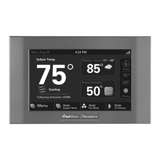
American Standard Gold 824
Connected Control
ACONT824 Installation Guide
ALL phases of this installation must comply with NATIONAL, STATE AND LOCAL CODES
IMPORTANT — This Document is customer property and is to remain with this unit.
These instructions do not cover all variations in systems or provide for every possible contingency to be met in connection with
the installation. Should further information be desired or should particular problems arise which are not covered sufficiently
for the purchaser's purposes, the matter should be referred to your installing dealer or local distributor.
WORKS WITH
11-HD13D1-10A-EN
Advertisement
Table of Contents

Summary of Contents for American Gold 824
-
Page 1: Contents
American Standard Gold 824 Connected Control ACONT824 Installation Guide WORKS WITH ALL phases of this installation must comply with NATIONAL, STATE AND LOCAL CODES IMPORTANT — This Document is customer property and is to remain with this unit. These instructions do not cover all variations in systems or provide for every possible contingency to be met in connection with the installation. -
Page 2: Table Of Contents
Installation Guide Contents 1. Safety ..............2 Load Value - Cooling ........32 2. Product Specifications .......... 3 Duty Cycles ..........32 Overshoot Clamp ........32 3. General Information ..........3 Stage Thresholds ........33 Overview ............3 Stage Inhibits ..........33 Contents ............ -
Page 3: Product Specifications
824 Programmable Wi-Fi Comfort Control Product Specifications SPECIFICATION DESCRIPTION Product Model ACONT824 Product Gold 824 824 Connected Control Size 5-1/2” x 3-3/8” x 1” (WxHxD) Configurations Heat Pump, Heat/Cool, Dual Fuel, Heat Only, Cooling Only Maximum Number of Stages 5 Stages Heat, 2 Stages Cooling Storage/Operating Temperature -40°F to 175°F, 5% to 95% RH non-condensing... -
Page 4: Installation
Installation Guide Installation Network Connections To take advantage of the full range of features on the 824 Location Control, it should be connected to the Internet. This is The 824 is designed for installation in climate controlled possible using either a wireless or a wired connection. living spaces. -
Page 5: Wiring
This side mounts to wall 824 Programmable Wi-Fi Comfort Control 6. Place the Sub-base against the wall in the desired FIGuRE 3. ATTACH RJ-45 HOLDER TO SuB-BASE location and mark the wall through the mounting holes. If you are using a wired Internet connection, be sure to mark the cutout for the RJ-45 connector (see Figure 2 on page 5). - Page 6 Installation Guide Field Wiring Connection Diagrams Heat/Cool Diagrams PAGE DIAGRAM DESCRIPTION DIAGRAM 1 1 OR 2 STAGE COOLING W/TAM7 MODEL VARIABLE SPEED AIR HANDLER DIAGRAM 2 1 STAGE COOLING W/GAM5A OR TAM4 MODEL AIR HANDLER DIAGRAM 3 1 STAGE COOLING W/GAM5B MODEL AIR HANDLER DIAGRAM 4 2 STAGE COOLING W/GAM5B MODEL AIR HANDLER DIAGRAM 5...
-
Page 7: Heat/Cool Applications
824 Programmable Wi-Fi Comfort Control Heat/Cool Applications 1- 1 OR 2 STAGE COOLING W/TAM7 MODEL VARIABLE SPEED AIR HANDLER Diagram 1 - 1 or 2 Stage Cooling w/TAM7 Model Variable Speed Air Handler 824 COMFORT CONTROL AUX1 AUX 1 NOTES: AUX1 1. - Page 8 Installation Guide Diagram 3 - 1 Stage Cooling w/GAM5B Model Air Handler 3- 1 STAGE COOLING W/GAM5B MODEL AIR HANDLER 824 COMFORT CONTROL AUX1 AUX 1 NOTES: AUX1 1. Y terminal must be connected at indoor unit for selected compressor air flow AUX2 AUX 2 INDOOR UNIT...
- Page 9 824 Programmable Wi-Fi Comfort Control Diagram 5 - 1 Stage Cooling w/GAF2-S Model Air Handler 5- 1 STAGE COOLING W/GAF2-S MODEL AIR HANDLER 824 COMFORT CONTROL AUX1 AUX 1 AUX1 AUX2 AUX 2 INDOOR UNIT AUX2 24VAC HOT OUTDOOR UNIT COMMON COOLING HEATING...
- Page 10 Installation Guide 7- 1 STAGE COOLING W/GAT2 & GAM2 MODEL AIR HANDLER Diagram 7 - 1 Stage Cooling w/GAT2 & GAM2 Model Air Handler 824 COMFORT CONTROL AUX1 AUX 1 AUX1 AUX2 AUX 2 INDOOR UNIT AUX2 24VAC HOT OUTDOOR UNIT COMMON COOLING HEATING...
- Page 11 824 Programmable Wi-Fi Comfort Control 9-1 STAGE COOLING W/TEM4 Diagram 9 - 1 Stage Cooling w/TEM4 Air Handler 824 COMFORT CONTROL AUX1 AUX 1 AUX1 AUX2 AUX 2 INDOOR UNIT AUX2 24VAC HOT OUTDOOR UNIT COMMON COOLING HEATING *Caution: Do not run Outdoor/Remote Optional sensor wires in the same bundle Outdoor...
- Page 12 Installation Guide 11- 1 STAGE COOLING W/GAS FURNACE Diagram 11 - 1 Stage w/Cooling Gas Furnace 824 COMFORT CONTROL AUX1 AUX 1 AUX1 AUX2 AUX 2 AUX2 INDOOR UNIT 24VAC HOT OUTDOOR UNIT COMMON COOLING HEATING *Caution: Do not run Outdoor/Remote Optional sensor wires in the same bundle Outdoor...
- Page 13 824 Programmable Wi-Fi Comfort Control 13-1 OR 2 STAGE COOLING w/S9V2 FURNACE Diagram 13 - 1 or 2 Stage Cooling with S9V2 Furnace 824 COMFORT CONTROL NOTES: AUX1 AUX 1 1. Cut and remove the BK jumper at the indoor unit AUX1 2.
- Page 14 Installation Guide 15- PACKAGE 1 STAGE HEAT/COOL W/NON-VARIABLE SPEED BLOWER Diagram 15 - Package 1 Stage Heat/Cool w/Non-Variable Speed Blower 824 COMFORT CONTROL AUX1 AUX 1 AUX1 AUX2 AUX 2 PACKAGE UNIT AUX2 24VAC HOT COMMON COOLING HEATING Optional *Caution: Do not run Outdoor/Remote Outdoor sensor wires in the same bundle Sensor*...
-
Page 15: Heat Pump Applications
824 Programmable Wi-Fi Comfort Control Heat Pump Applications 17- 1 OR 2 STAGE HEAT PUMP W/TAM7 MODEL AIR HANDLER Diagram 17 - 1 or 2 Stage Heat Pump w/TAM7 Model Air Handler 824 COMFORT CONTROL AUX1 AUX 1 AUX1 NOTES: AUX2 AUX 2 1. - Page 16 Installation Guide 19- 1 STAGE HEAT PUMP W/GAM5B MODEL AIR HANDLER Diagram 19 - 1 Stage Heat Pump w/GAM5B Model Air Handler 824 COMFORT CONTROL AUX1 AUX 1 AUX1 NOTES: AUX2 AUX 2 1. Y terminal must be connected at indoor unit for selected compressor air flow AUX2 INDOOR UNIT...
- Page 17 824 Programmable Wi-Fi Comfort Control 21- 1 STAGE HEAT PUMP W/GAF2-S MODEL AIR HANDLER Diagram 21 - 1 Stage Heat Pump w/GAF2-S Model Air Handler 824 COMFORT CONTROL NOTES: AUX1 AUX 1 1. Do not connect X2 when using this control. AUX1 AUX2 AUX 2...
- Page 18 Installation Guide 23- 1 STAGE HEAT PUMP W/GAT2 & GAM2 MODEL AIR HANDLER Diagram 23 - 1 Stage Heat Pump w/GAT2 & GAM2 Model Air Handler 824 COMFORT CONTROL AUX1 AUX 1 NOTES: AUX1 1. Do not connect X2 when using this control. AUX2 AUX 2 AUX2...
- Page 19 824 Programmable Wi-Fi Comfort Control Diagram 25 - 1 Stage Heat Pump w/TEM4 Air Handler 25- 1 STAGE HEAT PUMP W/TEM4 MODEL AIR HANDLER 824 COMFORT CONTROL AUX1 AUX 1 NOTES: AUX1 1. Do not connect X2 when using this control. AUX2 AUX 2 AUX2...
- Page 20 Installation Guide Diagram 27 - Package 1 or 2 Stage Heat Pump w/Variable Speed Blower 27 - Package 1 or 2 Stage Heat Pump w/Variable Speed Blower 824 COMFORT CONTROL AUX1 AUX 1 NOTES: AUX1 1. Remove “R” to “BK” jumper and clip all “Y” connections at the integrated motor control board AUX2 AUX 2...
- Page 21 824 Programmable Wi-Fi Comfort Control 29 - AMERISTAR 1 STAGE HEAT PUMP Diagram 29 - Ameristar 1 Stage Heat Pump 824 COMFORT CONTROL AUX1 AUX 1 AUX1 NOTES: AUX2 AUX 2 1. D at the Outdoor Unit must be wired to W1 or W2 for electric heat during defrost AUX2 INDOOR UNIT...
-
Page 22: Dual Fuel Applications
Installation Guide Dual Fuel Applications 30 - 1 OR 2 STAGE HEAT PUMP W/VARIABLE SPEED GAS FURNACE Diagram 30 - 1 or 2 Stage Heat Pump w/Variable Speed Gas Furnace 824 COMFORT CONTROL AUX1 AUX 1 AUX1 NOTES: AUX2 AUX 2 1. - Page 23 824 Programmable Wi-Fi Comfort Control Diagram 32 - 1 or 2 Stage Heat Pump w/S9V2 Furnace 32 - 1 OR 2 STAGE HEAT PUMP w/S9V2 FURNACE 824 COMFORT CONTROL NOTES: AUX1 AUX 1 1. Cut and remove the BK jumper at the indoor unit AUX1 2.
-
Page 24: System Setup
Installation Guide System Setup user Setup Wizard The User Setup Wizard is accessed navigating to Power-up Sequence Home>Menu>Settings>User Setup Wizard. By following the When the 824 Control is connected to the Sub-base, the navigational steps and screen prompts, homeowners are Control initiates a 90-120 second power-up sequence. -
Page 25: Installer Setup Screens
824 Programmable Wi-Fi Comfort Control Installer Setup Screens From the Installer Setup screens, individual parameters are configured and modified. Use the up and down arrows to scroll through the groups of settings. To change a setting contained in a particular group, press Edit and press Next to navigate to the desired setting. -
Page 26: Group 4 Accessories Settings
Installation Guide 5.4.4 Group 4 Accessories Settings MENu ITEM OPTIONS [DEFAuLT] DESCRIPTION Air Cleaner, Filtration Type Installed Select the filter type installed [Media Filter] Humidifier Installed [None], Yes Select whether a humidifier is installed Humidifier - Select Aux Contact [Aux1], Aux2 Select which set of Aux contacts is controlling the humidifier Humidifier Type [Powered/Bypass], Steam... -
Page 27: Group 5 Comfort Settings
824 Programmable Wi-Fi Comfort Control 5.4.5 Group 5 Comfort Settings MENu ITEM OPTIONS [DEFAuLT] DESCRIPTION Select if enhanced dehumidification features are enabled. See section Enable Dehumidification [Enable], Disable 7.2 Advanced Operation - Dehumidification for additional information. Select the maximum amount of overcooling allowed when the indoor Dehumidification Overcooling Limit - Degrees [0°] to 3°F humidity exceeds the cooling target humidity setpoint. -
Page 28: Group 6 Airflow Settings
Installation Guide 5.4.6 Group 6 Airflow Settings MENu ITEM OPTIONS [DEFAuLT] DESCRIPTION [No Delay], Select the blower on delay for cooling operation Enhanced Mode, 7.5 Minutes @ 80%, VS Blower On Delay - Clg Enhanced Mode is a tiered Blower On Delay for 4 Minutes @ 80%, variable speed blowers only (1 minute at 50%, 1 Minute @ 50%,... -
Page 29: Group 7 Lockout Settings
824 Programmable Wi-Fi Comfort Control 5.4.7 Group 7 Lockout Settings An Outdoor Temperature Sensor must be enabled for Lockout settings to be selectable. MENu ITEM OPTIONS [DEFAuLT] DESCRIPTION Enable auxiliary heat lockout (10° minimum separation when enabling Auxiliary Heat Lockout [Disable], Enable auxiliary heat lockout and compressor heat lockout) Select an outdoor temperature to prevent auxiliary heat above the selected... -
Page 30: Basic Operation
Installation Guide Basic Operation Load Value - Cooling 0-100 Single Stage Compressor PI Control 0-200 Two-Stage Compressor The 824 Control uses proprietary control schemes to A Load Value of 50 represents a request of 50% demand provide comfort and energy efficiency. The Control senses for single stage cooling units (“Y”) or 50% demand for stage indoor temperature and determines capacity needed based one of multistage cooling units (“Y1”). -
Page 31: Stage Thresholds
824 Programmable Wi-Fi Comfort Control Stage Thresholds Stage Inhibits The threshold to allow operation is a Load Value greater When the stage threshold is exceeded, a stage inhibit is than 5 and operation is always terminated with a Load applied. The stage inhibit calculates the rate of recovery Value less than 1. -
Page 32: Fan Mode
Installation Guide System Mode The 824 has (5) System Modes which can be selected… Heating, Cooling, Off, Emergency Heat and Auto. • Heating – System will only operate in heating mode • Cooling – System will only operate in the cooling mode •... -
Page 33: Advanced Operation
824 Programmable Wi-Fi Comfort Control Advanced Operation Dehumidifier Operation The 824 has the ability to control a Whole-House Control response rate Dehumidifier through the normally open dry AUX contacts Allows the user to select a set of higher proportional- on the 824 Control Sub-base. Control options are: integral control constants to increase the responsiveness •... -
Page 34: Lockouts
Installation Guide • Restricted Mode (compressor heat only) – Once Restrict Compressor enabled an outdoor temperature lockout can be set and Aux Heat to disable compressor heating operation. When the outdoor temperature falls below the compressor heat lockout the system will operate on auxiliary 70º... -
Page 35: Humidifier Operation
824 Programmable Wi-Fi Comfort Control • Furnace Heating 1st Stage Lockout – Once enabled, the outdoor temperature exceeds the minimum or maximum select an outdoor temperature which forces 2nd stage outdoor temperature selections. If outdoor temperature furnace heating operation. overrides are enabled the user can select to accumulate the missed ventilation run time. -
Page 36: Diagnostic Tools
Installation Guide Diagnostic Tools Test Modes Access Test Modes by navigating to Service Menu>Test Modes. All test modes will terminate automatically after 60 minutes or can be terminated manually at any time. MODE SETTINGS DESCRIPTION Test Blower 50%, 100% Energize indoor blower at the selected speed Stage 1 Energize the selected stage of cooling operation. -
Page 37: System Report
824 Programmable Wi-Fi Comfort Control System report The System Report Screen provides technicians with important system operational data in one, concise screen. The data is provided in real-time and updates as the data changes. The System Report Screen displays the following data points: —... -
Page 38: Troubleshooting
Installation Guide Troubleshooting SYMPTOM POSSIBLE CAuSES ACTION Control displays an alert code on A critical or major alert is present. Navigate to the Diagnostic screen on the 824 Control for a the screen. Problem Description and Possible Cause. Display will not come on Loss of 24VAC between R &... -
Page 39: Notices
824 Programmable Wi-Fi Comfort Control 10. Notices 10.1 FCC Notice INFORMATION TO USER This device complies with Part 15 of the FCC Rules. Operation is subject to the following two conditions: (1) This device may not cause harmful interference and (2) This device must accept any interference received, including interference that may cause undesired operation. - Page 40 About American Standard Heating and Air Conditioning American Standard has been creating comfortable and affordable living environments for more than a century. For more information, please visit www.americanstandardair.com. The manufacturer has a policy of continuous data improvement and it reserves the right to change design and specifications without notice. We are committed to using environmentally conscious print practices.
Need help?
Do you have a question about the Gold 824 and is the answer not in the manual?
Questions and answers