Advertisement
Quick Links
P.O.Number :
Please Keep This Number For
Future Reference
THIS FORMS PARTS OF
YOUR GUARANTEE!
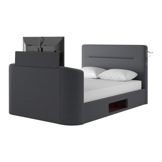
Re-charge Gaming Bed Inc Ottoman Storage 120 / 135 / 150 cm
Minimum two
person assembly
2 Hr
Approximate
Assembly Time
Product Details
STK811203
4' Bed Black Woven
STK811201
4'6 Bed Black Woven
STK811202
5' Bed Black Woven
STK811207
4' Bed Charcoal Grey
STK811205
4'6 Bed Charcoal Grey
STK811206
5' Bed Charcoal Grey
Regrettably self-assembly items cannot be returned once assembly is part or fully completed unless the
items are found to be faulty.Should you need to return the un assembled product, please repack in its original
packaging.
lmportant Information
● We suggest you spend a short time reading through this leaflet and then follow the simple step-by-step
instructions.
● Carefully check that you have all the parts before beginning assembly.
● Keep fittings out of children's reach and keep children well away from construction area.
● We suggest you retain these instructions for future reference.
Product Information
● Side lift up storage TV bed.
● Bedframe conforms to BSEN1725. Fabrics and fillings conform to BS5852.
● TV Lift system has a maximum load capacity of 80lbs ( 37kg )
● Compatible with slimline LED televisions with a screen size of 20" to 43".
Care Instructions
● Avoid exposing the furniture to excessive heat or direct sunlight as this can cause cracking or
deterioration of the color.
● Periodically check & re-tighten any screws and fixings.
● Periodically dust lightly with a clean soft cloth.
● TAKE CARE WHEN MOVING THE FURNITURE AND NEVER DRAG THE PIECES ACROSS
THE FLOOR,AS THIS WILL CAUSE DAMAGE TO THE JOINTS.
Whereas every effort has been made to allow thls product to utlllse the maxlmum number of TV's
available it is not possible to accommodate every product in an ever changing market lt is the
responsibility of the customer to ensure suitability of the TV to the TV bed before attempting
operation. It is the customers responsibility to ensure all wiring is correctly placed in accordance
with both the TV and TV bed manufacturer.
Bensons for Beds will not be held responsible for any damage caused to the TV, TV Cabling or TV
bed due to incompatibility of equipment used.
Conforms To:
The Re-charge Ottoman Gaming BED conforms to the followings standards:-
(REV 04 12/12/2023)
Assembly lnstructlons
Please keep these lnstructlons for future reference.
Model: 2.1 Remote:
UKCA & CE: RED(EMC+RF+Health) + LVD
- EN/BS 301489, EN/BS 300440, EN/BS 62368, EN/BS 62479 ROHS Directive
Model: 2.1 Audio:
UKCA & CE: RED(EMC+RF+Health) + LVD
- EN/BS 301489, EN/BS 300328 EN/BS 62479, EN/BS 62368, ROHS Directive
Page 1 of 34
Advertisement

Related Manuals for Bensons for Beds STK811203


Summary of Contents for Bensons for Beds STK811203
- Page 1 It is the customers responsibility to ensure all wiring is correctly placed in accordance with both the TV and TV bed manufacturer. Bensons for Beds will not be held responsible for any damage caused to the TV, TV Cabling or TV bed due to incompatibility of equipment used.
- Page 2 Components of Carton A A Head End x 1 Components of Carton B B Side Rail-1 x 1 Side Rail-2 x 1 NOTE: The side rails are interchangeable and can be located on either side. Decide which side the media compartment will be, (Side Rail before starting assembly.
- Page 3 Components of Carton E U Base Panel x 4 Components of Carton F V Media Storage Compartment x1 (REV 04 12/12/2023) Page 3 of 34...
- Page 4 Tips before you start! 1. Please check that all parts are present before you start the assembly of your furniture. 2. For ease and speed of assembly, we recommend that before you commence each step of the assembly, that you identify all the parts required for that step. 3.
- Page 5 Step 1 ● Assemble feet to underside of headboard and footboard. ● Footboard has 2 feet each side. Headboard has 1 foot each side. NOTE: The feet and screws are both packed inside carton D. AI x 6 (REV 04 12/12/2023) Page 5 of 34...
- Page 6 4FT Small Double Right Side Access Finished Step 2a ( Choose which side you want to lift up) Assembly NOTE: The media storage compartment must be on the same side as the ottoman opening. ● Check this diagram and if access is needed from Right side of bed, fit both lift mechanisms as shown.
- Page 7 4FT6 Double Right Side Access Finished Step 2a ( Choose which side you want to lift up) Assembly NOTE: The media storage compartment must be on the same side as the ottoman opening. ● Check this diagram and if access is needed from Right side of bed, fit both lift mechanisms as shown.
- Page 8 5FT King Right Side Access Finished Step 2a ( Choose which side you want to lift up) Assembly NOTE: The media storage compartment must be on the same side as the ottoman opening. ● Check this diagram and if access is needed from Right side of bed, fit both lift mechanisms as shown.
- Page 9 Step 3 ● Before assembly please decide which side you require the "DVD / Media Compartment " Part side rail (with opening) will need to be placed at that side. ● Screw fixings loosely into headboard and footboard ● With help, carefully hook side rails over the screws.
- Page 10 Step 4 ● Assemble retaining strap to side rail using strap bracket AE x 1 AF x 1 X x 2 AA x 2 AB x 2 (REV 04 12/12/2023) Page 10 of 34...
- Page 11 Step 5 - Headboard cable connection ● Remove front cover from trunking at the bottom edge of the right hand side rail ● Place cables inside trunking and replace cover. ● Turn the cover cap at the bottom of headboard to access the cables inside.
- Page 12 STEP 6a - Footboard cable connection (Right Side Ottoman Access) ● Turn the cover cap at the bottom of footboard to access the cables inside. ● Pull out the cables and connect to cables ● Note: Cables are labelled. Ensure they are connected to the corresponding cables in the footboard.
- Page 13 STEP 6b - Footboard cable connection (Left Side Ottoman Access) ● Turn the cover cap at the bottom of footboard to access the cables inside. ● Pull out the cables and connect to cables ● Note: Cables are labelled. Ensure they are connected to the corresponding cables in the footboard.
- Page 14 Step 7 Locate the remote control which is packed inside a box secured to the TV mast inside the foot end (carton C). ● install batteries into remote control. Requires x3 "AAA" batteries Step 8 REMOTE CONTROL IMPORTANT - Remote Control is packed inside the Footboard.
- Page 15 Step 9 ● Plug power cable into footboard ● Connect to a wall socket but do not switch power on. ● Plug extension cable into one of the available sockets on the electrical panel at the bottom of the footboard. Connect to wall socket IMPORTANT...
- Page 16 Step 10 ● For easier access during TV installation, carefully remove the TV compartment lid as shown. Gooseneck Gooseneck Carefully pull upwards to remove Remove gooseneck Remove TV compartment (REV 04 12/12/2023) Page 16 of 34...
- Page 17 Step 11 ● To adjust the TV tray to suit the height of your TV (without stand). Please follow steps below 11.1 : Measure and make a note of the height of your TV (without stand!). 11.2 : Use Allen key to slightly loosen the up / down adjuster bolts (quarter turn only).
- Page 18 Step 12 ● You are now ready to install the TV. ● Using the remote control, raise the TV lift mechanism to it's highest position. ● While standing behind your television (on the outside end of the footboard facing the headboard) carefully place the TV on top of the two rubber TV mounting blocks.
- Page 19 Step 14 ● Once the TV is assembled to the mast, lift it clear of the two rubber pads and ensure it is pushed fully back against the mast. ● Lower back down onto the pads. ● Before operating the TV lift, visually check that the TV is completely clear of the surrounding frame! Lift TV Ensure bottom of...
- Page 20 Step 16 ● If necessary the rubber blocks can be adjusted to align correctly with the front of the TV. ● IMPORTANT: It is important the rubber blocks do not overhang the front edge of the TV platform. Must not overhang Adjust to suit...
- Page 21 Step 17 ● The following cables have been supplied: HDMI Cable, Power Cable, Optical Cable. ● Connect the optical and HDMI cables as shown. Note: The drawing is for illustration purposes only. Cables and port locations may vary according to the actual TV set. The bed manufacturer will not accept any responsibility for faults or damages caused by incorrect installation.
- Page 22 Step 18 ● Complete all cable connections for the games console or other devices. ● Games console HDMI plugs into the socket at the base of the footboard. ● Games console power cable plugs into extension lead Games Console HDMI Games Console Power Cable (REV 04 12/12/2023)
- Page 23 Step 19 PLAYING SOUND THROUGH THE TV - (OPTICAL MODE) ● Ensure the optical cable is correctly connected between the television and bed. ● Ensure the Television is powered on and playing a picture with sound. ● Use the remote control to adjust the volume / base according to your sound preferences. TROUBLE SHOOTING ●...
- Page 24 Step 21 ● Attach velcro pads to feet ● Attach feet to the underside of base panels ● The feet are attached to the velcro pads. Step 22a (Right Side Ottoman Access) ● Carefully place base panels into position. ● Ensure extension is routed through the central hole between the base panels.
- Page 25 Step 22b (Left Side Ottoman Access) ● Carefully place base panels into position. ● Ensure extension cable and LED light cable are both routed through the central hole between the base panels. ● Take care to ensure the base panel feet do not trap any of the cables. Left Side Access (REV 04 12/12/2023) Page 25 of 34...
- Page 26 Step 23a (Right Side Ottoman Access) ● Carefully assemble DVD / Media storage Compartment to the inside of side rail ● Ensure it is located with the up arrows pointing up. ● Connect the led light cable to the corresponding cable .
- Page 27 Step 23b (Left Side Ottoman Access) ● Carefully assemble DVD / Media storage Compartment to the inside of side rail ● Ensure it is located with the up arrows pointing up. ● Connect the led light cable to the corresponding cable .
- Page 28 Step 24 ● With help, carefully open out the folding mattress base ● Secure in the open flat position using metal plates AE x 1 X x 4 AA x 4 AJ x 2 (REV 04 12/12/2023) Page 28 of 34...
- Page 29 Step 25a (Right Side Ottoman Access) ● With help, carefully lift mattress base into position and secure using fixings as shown using three bolt sets on each side, & ● Be careful to ensure the holes for mattress retainers are located on the lower side. ●...
- Page 30 Step 25b (Left Side Ottoman Access) ● With help, carefully lift mattress base into position and secure using fixings as shown using three bolt sets on each side, & ● Be careful to ensure the holes for mattress retainers are located on the lower side. ●...
- Page 31 Step 26 ● With help, carefully open up lift up mechanisms IMPORTANT: Beware of finger entrapment from moving parts. ● Remove the pre-assembled nut, locate the end of the of the piston as shown, then replace nut. Locate piston Replace Remove Nut pre-assembled (REV 04 12/12/2023)
- Page 32 Step 27 ● Attach fabric retaining strap to the centre of the upper side of mattress base ● IMPORTANT: For safety purposes use retaining strap to help retain the mattress base in it's lowered position. (REV 04 12/12/2023) Page 32 of 34...
- Page 33 Step 28 ● IMPORTANT: Place the mattress onto the base before attempting to lower or lift it. MATTRESS lift up pull down A.This Lift Mechanism provides assistance in lifting the mattress. It does not lift the mattress for you. The system has been designed to effectively lift the base system with a variety of mattress weights and combinations of depth.
- Page 34 Step 29 ● Make sure the 4 corners of the bed frame are at 90 degrees before closing the mattress base. If necessary, loosen the side rail bracket fixings (see step 3) to adjust and re-align. Fully retighten all fixings after any adjustment. LEFT Adjust if necessary RIGHT...
Need help?
Do you have a question about the STK811203 and is the answer not in the manual?
Questions and answers