Table of Contents
Advertisement
Quick Links
Advertisement
Chapters
Table of Contents

Related Manuals for Art ARTTRACK


Summary of Contents for Art ARTTRACK
- Page 1 Text als Fake ... ART Hardware Installation Guide ARTTRACK, TRACKPACK, SMARTTRACK & DTRACK Version 3.2.0 May 2023 c 2023 Advanced Realtime Tracking GmbH & Co. KG Contents are subject to change without notice dasbetrifft die gesamte seitenbreite der seite des...
- Page 2 The following overview shows the registered trademarks of Advanced Realtime Tracking GmbH & Co. KG: trademarks illustrated as in Germany in the EU in the U.S. A.R.T. ARTtrack ARTTRACK DTrack DTRACK3 smARTtrack SMARTTRACK Microsoft and Windows are trademarks registered in the United States and other countries by the Microsoft Corporation.
- Page 3 Warranty regarding further use of open source software Advanced Realtime Tracking GmbH & Co. KG (denoted as ) provides no warranty for the open source software programs contained in this product, if such programs are used in any manner other than the program execution intended by .
- Page 4 ARTTRACK6/M for Active Markers Flystick2+ Edition January 2021 The following products have been added: ARTTRACK6/M Installation Edition May 2020 The following products have been added: ART Controller/M Installation Edition October 2019 The following products have been added: SMARTTRACK3 Installation including Cascaded System capability...
-
Page 5: Table Of Contents
4.2 Controller ........28 4.2.1 ART Controller ......28 4.2.2... - Page 6 5.2 Installation of the Controller ......52 5.2.1 Installation of the ART Controller ....52 5.2.2 Ports &...
- Page 7 SMARTTRACK2 5.9.1.4 Mounting the (discontinued) ..100 5.9.2 Installation of the ARTTRACK Controller (discontinued) ..101 5.9.3 Installation of the TRACKPACK Controller (discontinued) ..103 5.9.4 Installation of the...
- Page 8 A.2 Controller ........130 A.2.1 ART Controller ......130 A.2.2...
- Page 9 Index...
-
Page 10: Terms And Definitions
five degrees of freedom (i.e. one degree less in orientation) base imaginary connecting line between two cameras (e.g. the two integrated cameras inside the SMARTTRACK2/3/M ART Controller controller for rackmounting, calculates tracking data and gener- ates the data output stream (compatible to ARTTRACK2 ART-... - Page 11 SMARTTRACK2 Synccard unit integrated in SMARTTRACK2/3/M which serves for syn- chronizing the cameras Synccard2 board integrated in the ARTTRACK Controller (discontinued) which serves for synchronizing the cameras Synccard3 ART Controller ART Con- board integrated in the troller/M which serves for synchronizing the cameras...
- Page 12 term definition TRACKPACK/E infrared camera TRACKPACK Controller (discontin- calculates tracking data and generates the data output stream ued) (compatible to TRACKPACK TRACKPACK/C virtual point cloud used for calculating the relative position of cameras or SMART- TRACK2/3/M that cover the measurement volume wand precalibrated stick carrying two markers.
-
Page 13: Safety
1 Safety 1.1 Symbols and their meaning You can find the following symbols and signs on the equipment or in the manual: Useful and important notes. Important notes, which may lead to system malfunction or to the loss of warranty by non-observance. Important safety warning to assure user’s and operational safety. -
Page 14: Mounting
1 Safety Do not install or use any equipment when the power cord is damaged. Insert batteries in the indicated polarity ! Some equipment employs connectors of proprietary design. Do not try to connect these to any other computer ports (e.g. COM port or LAN) Verify that voltage and frequency of your electrical grid comply with the appliance ratings of the equipment. -
Page 15: Operation
The ventilation holes of the equipment (particularly of SMART- TRACK2 ARTTRACK2 ART Controller ART Controller/M ) must not be covered. Ensure unblocked airflow at all times. The minimum distance between equipment and surrounding objects has to be larger than 3 cm. -
Page 16: Maintenance
! Risk of electric shock - even if the equipment is disconnected. Please contact service. All warranty and liability is void when the equipment is opened. In order to replace mains fuses (e.g. ART Controller ) always unplug the power cord first. Risk of electric shock ! -
Page 17: Disposal & Recycling
1.2 Warnings Risk of explosion if removable batteries are replaced by an incorrect type! 1.2.5 Disposal & Recycling Waste Electronic and Electrical Equipment (WEEE) should never be disposed of along with household waste. Batteries should never be disposed of along with household waste. Batteries or rechargeable batteries that are not permanently installed must be removed beforehand and disposed of separately. -
Page 18: General Information
2 General Information 2.1 Cleaning of the equipment Use a dry, lint-free and antistatic cloth or tissue (e.g. lens-cleaning tissue for optical equipment). Only the housing of the cameras may be cleaned. Before cleaning shut down the system and disconnect the power cords. Do not use any solvents, water or chemicals to clean the cameras! 2.2 Maintenance and service Routine maintenance of the equipment is recommended every three years. - Page 19 For further details regarding the WEEE directive, including how ensures the safe disposal of your electrical and electronic equipment, please refer to our website at https://ar-tracking.com/de/art-geraete-ruecknahmekonzept Waste Electronic and Electrical Equipment (WEEE) should never be disposed of along with household waste.
-
Page 20: Disposal And Recycling Of Batteries
For further details regarding the Battery Directive, please refer to our website at https://ar-tracking.com/de/art-geraete-ruecknahmekonzept Batteries should never be disposed of along with household waste. Batteries or rechargeable batteries that are not permanently installed must be removed beforehand and disposed of separately. -
Page 21: Warranty
2.5 Warranty 2.5 Warranty General Please refer to the terms & conditions on our website at https://ar-tracking.com/en/terms-agb Hardware warrants the hardware to be free from defects in material and workman- ship, design and manufacturing for the warranty period set forth in our terms & conditions (see website) after the time of delivery. - Page 22 2 General Information interruption, loss of business information, or any other pecuniary loss) arising out of the use of or inability to use the software or hardware. Measurement results products are not authorized for use under any circumstance where human life might be at risk due to malfunction, measurement errors or interrupted operation of the system without written approval of a managing director of It is the user’s sole responsibility to check the results of the measurement data and to protect any downstream system against malfunction, measurement errors or interrupted...
-
Page 23: Introduction To Tracking
3 Introduction to tracking tracking systems are infrared (IR) optical tracking systems, whereas the SMART- TRACK2/3/M are fully integrated stand-alone tracking systems, designed to be used in small volumes (approx. 2m ). In this user manual we are going to perceive "tracking" as measurement of positional and rotational information (i.e. - Page 24 3 Introduction to tracking Note: In pure optical tracking systems tracking is only possible as long as objects or individuals to be tracked are equipped with single markers or targets the target is not occluded by any other objects in the cameras’ line of sight, which could even be the object itself the target is positioned inside the tracking range of the cameras at least four markers of a target are visible to at least two cameras (this step enables...
- Page 25 tracking data from IMUs offers low noise-levels while running at very high frequen- cies in combination with low latencies IMUs deliver tracking data (i.e. rotational information) even when the optical target is not inside the tracking volume or if the target cannot be tracked due to viewing limitations or occlusions drifting of IMUs (i.e.
-
Page 26: Hardware Components
4 Hardware Components 4.1 Cameras 4.1.1 ARTTRACK6/M Keep a distance of min. 20 cm when operating the camera ! The camera is assigned to the Exempt Group according to IEC62471-1 and therefore poses no risk or hazard to the human eye or skin at this dis- tance. -
Page 27: Arttrack6/M For Active Markers
4.1 Cameras 4.1.1.1 ARTTRACK6/M for Active Markers Description The ARTTRACK6/M for Active Markers camera is intended for use with active markers only. It features the same specifications (dimensions, working environ- ARTTRACK6/M ment, available focal lengths of lenses, field of view, etc.) as the lacks an infrared flash. -
Page 28: Arttrack5/C
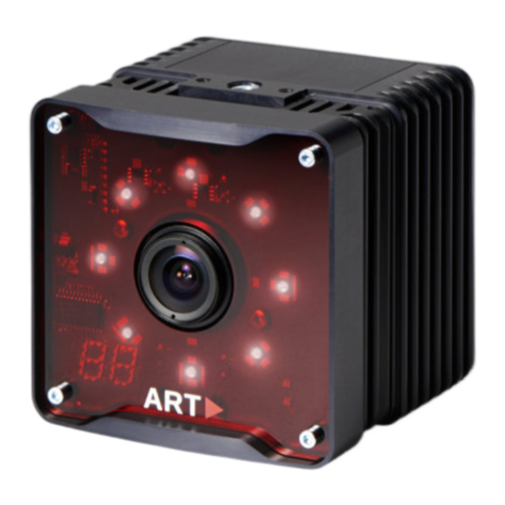
126 for more information. Figure 4.3: Camera ARTTRACK5/C - Description of LEDs and interface connectors ARTTRACK5/C camera may be combined and mixed with the ART- TRACK5 TRACKPACK/E camera in one tracking system. Alterna- tively a tracking system may consist of ARTTRACK5/C cameras only. -
Page 29: Trackpack/E
(optional) and targets respectively. The backend software runs on the controller - all necessary calculations (3DOF, 6DOF data, etc.) are performed there. 4.2.1 ART Controller Description The ART Controller comes in a 19" inch housing compatible for rack... -
Page 30: Art Controller/M
4 Hardware Components (a) front view (b) back view Figure 4.5: ART Controller The ventilation holes of the ART Controller must not be covered. En- sure unblocked airflow at all times. The minimum distance between equipment and surrounding objects has to be larger than 3 cm. - Page 31 4.2 Controller (a) front view (b) back view Figure 4.6: ART Controller/M The ventilation hole on the back of the ART Controller/M must not be covered. Ensure unblocked airflow at all times. The minimum distance between equipment and surrounding objects has to be larger than 3...
-
Page 32: Compatibility
4 Hardware Components 4.2.3 Compatibility ART Con- ARTTRACK TRACKPACK DTRACK3 Controller troller/M Controller Controller ARTTRACK1 ARTTRACK2 ARTTRACK3 ARTTRACK5 ARTTRACK5/C ARTTRACK6/M TRACKPACK TRACKPACK/C TRACKPACK/E Flystick2 Flystick2+ Flystick3 Fingertracking FINGERTRACKING2 Tactile Measurement Tool Trivisio wireless IMU Yost Labs wired IMU only syncgroup #1 available... - Page 33 4.3 Integrated systems Figure 4.7: SMARTTRACK3 - Front & Back view Figure 4.8: SMARTTRACK3/M - Front & Back view...
-
Page 34: Other Equipment
Please use the accessible ports without protective caps only. To turn on the PoE+ switch, please connect it to mains or external power supply respectively. Table 4.2: Compatible PoE+ switches authorized by Please allow min. 3 minutes for booting prior to starting the ART Con- troller ART Controller/M... -
Page 35: Radiotransceiver2/3
4.4 Other equipment Due to non-default settings do not tamper with the configuration of all managed switches authorized by . Ask your representative for details when necessary. Use only original components and accessories from or authorized . Using unauthorized components or accessories may damage the equipment, may cause malfunctioning and may compromise oper- ational safety. -
Page 36: Discontinued Hardware
4 Hardware Components 4.5 Discontinued hardware 4.5.1 ARTTRACK2 Keep a distance of min. 20 cm when operating the camera ! The camera is assigned to the Exempt Group according to IEC62471-1 and therefore poses no risk or hazard to the human eye or skin at this dis- tance. -
Page 37: Trackpack
By default the ARTTRACK3 equipped with a 4.5 mm lens. Depending on the application and the setup the ART- TRACK3 can be equipped with other lenses (i.e. with different focal lengths). Refer to A.1 on page 126 for a list of available focal lengths and the respective FoV. -
Page 38: Trackpack/C
4 Hardware Components Figure 4.13: Camera TRACKPACK - Description of LEDs and interface connectors 4.5.4 TRACKPACK/C Keep a distance of min. 20 cm when operating the camera ! The camera is assigned to the Exempt Group according to IEC62471-1 and therefore poses no risk or hazard to the human eye or skin at this dis- tance. -
Page 39: Smarttrack2
4.5 Discontinued hardware Figure 4.14: Camera TRACKPACK/C - Description of LEDs and interface connectors 4.5.5 SMARTTRACK2 Keep a distance of min. 20 cm when operating the SMARTTRACK2 SMARTTRACK2 is assigned to the Exempt Group according to IEC62471-1 and therefore poses no risk or hazard to the human eye or skin at this distance. - Page 40 4 Hardware Components Figure 4.15: SMARTTRACK2 - Front & Back view Figure 4.16: 3D Visualization of the tracking volume...
-
Page 41: System Setup
5 System setup 5.1 Setting up the cameras 5.1.1 Camera orientation While mounting the cameras or SMARTTRACK2/3/M it is vital to adjust the orientation of each camera and the SMARTTRACK2/3/M respectively such that the measurement volume is covered completely by the field of view (FoV) of all cameras. On the one hand camera mounting has to ensure that tracking is possible over the entire measurement volume. -
Page 42: Mutual Blinding
5 System setup Figure 5.1: Typical situation arising from reflections through sunlight mutual blinding of opposing or adjacent cameras any kind of reflective material on clothes or shoes (e.g. reflective tape on safety vests), blank metal surfaces that act as mirrors, especially curved surfaces and polished surfaces with 90 angles, some types of packaging foils. -
Page 43: Assigning Syncgroups (Available For Art Cameras And Smart- Track3 & Smarttrack3/M Cascades Only)
5.1 Setting up the cameras next to the number of markers seen / used for tracking may serve as another indicator. In order to distinguish from targets or other reflections please remove all reflective mark- ers from the measurement volume in the first step. Then check whether the Monitor 2DOF display still shows the presence of markers and whether the LED bar shows high levels... -
Page 44: Static Reflex Suppression
5 System setup 5.1.4 Static reflex suppression If, by any means, reflections cannot be eliminated completely you may use the static DTRACK3 reflex suppression of ,i.e. blocking individual areas of the FoV / measure- ment volume to eliminate mutual blinding. DTRACK3 , all cameras and... - Page 45 5.1 Setting up the cameras Figure 5.3: Origin of the room coordinate system (default) calibration is always the first step. Without it, body calibration and tracking will not be possible. Example: If a camera with 3.5mm lenses (standard for ARTTRACK5 TRACKPACK/E ) is rotated by one tenth of a degree it will cause aber- rations of the optical rays that are as high as 5 millimetres in 3 metres...
-
Page 46: Room Calibration Hardware
5 System setup 5.1.5.3 Room calibration hardware To perform a room calibration two pieces of hardware are needed, the ’calibration angle’ (see figure 5.4 on page 45) of the "room calibration set" and the ’wand’. The position and orientation of the ’calibration angle’... -
Page 47: Mounting The Cameras
5.1 Setting up the cameras Figure 5.5: Room calibration process If in a system setup no sufficient part of the measurement volume is seen by all IR cam- eras simultaneously, the point cloud created by the ’wand’ movement has to connect all cameras in a way that ensures the arrangement of all cameras in a common room coor- dinate system. -
Page 48: Tripod Mounting
. Do not forget the toothed washer ! The ventilation holes of the equipment (particularly of SMART- TRACK2 ARTTRACK2 ART Controller ART Controller/M ) must not be covered. Ensure unblocked airflow at all times. The minimum distance between equipment and surrounding objects has to be larger than 3 cm. -
Page 49: Mounting The Arttrack6/M
5.1 Setting up the cameras Figure 5.6: Attaching the T-Piece to the SMARTTRACK2/3/M Figure 5.7: Mounting a camera to a wall or a ceiling (e.g. ARTTRACK2 camera) Feel free to contact in case you want to realise a complex installation. We will assist you in your planning. -
Page 50: Mounting The Arttrack5
5 System setup Figure 5.8: Attaching the ceiling suspension to the ARTTRACK6/M camera 5.1.6.5 Mounting the ARTTRACK5 The ceiling suspension can be attached on both bottom and top side of the camera. Attach the carrier with the T-piece to the camera as shown in figure 5.9 on page 50. For more flexibility, the T-piece can be mounted pointing forward or backward. - Page 51 5.1 Setting up the cameras Figure 5.9: Attaching the ceiling suspension to the ARTTRACK5 camera Figure 5.10: Camera ARTTRACK5/C remote head (back) ARTTRACK5/C remote head has to be connected to its corre- sponding camera body. During mounting please ensure matching se- rial numbers for both parts !
-
Page 52: Mounting The Trackpack/E
(internal in SMARTTRACK2/3/M ) is not ob- structed. Connecting the cameras For connecting the cables to the controllers please refer to the respective chapters: ART Controller : 5.2.1 on page 52 ART Controller/M : 5.2.3 on page 55 SMARTTRACK3 &... -
Page 53: Installation Of The Controller
5.2 Installation of the Controller ARTTRACK Controller (discontinued): 5.2 on page 52 SMARTTRACK2 (discontinued): 5.9.4 on page 104 TRACKPACK Controller (discontinued): 5.9.3 on page 103 The power cord and plug should be accessible freely. The power socket should be close to the equipment. -
Page 54: Ports & Plugs On The Art Controller
5 System setup Guide Hardware Inertial Sensors). You can also plug-in a USB pen drive for accessing the ART Controller without the DTRACK3 frontend (refer to DTRACK3 User’s Guide Connecting to the controller The ventilation holes of the ART Controller must not be covered. - Page 55 Defines syncgroup #3. The default time delay related to syncgroup #1 is For cascaded systems please connect ’OUT1’ to ’ExtIn’ of a slave controller (see chapter 5.6 on page 66). ART Synccard3 (master PCI card ONLY): – ’ExtIn’: Please plug in the external source (TTL or video signal or master controller of a cascaded system) for synchronization here.
-
Page 56: Installation Of The Art Controller/M
5 System setup Figure 5.14: ART Controller/M front view 5.2.3 Installation of the ART Controller/M ART Controller/M is powered via an external power supply, there is no power switch. ART Controller/M To turn on the press the button ’soft power on’... -
Page 57: Ports & Plugs On The Art Controller/M
5.2 Installation of the Controller 5.2.4 Ports & Plugs on the ART Controller/M The following list gives a short overview of all ports accessible to the user (see figure 5.15 on page 56): ART Controller/M Figure 5.15: back view ART Synccard3 (IN &... - Page 58 (refer to chapter 4.4.2 on page 34), Trivisio wire- less transceivers and Yost Labs wired inertial sensors (refer to DTRACK3 User’s Guide Hardware Inertial Sensors) You can also plug-in a USB pen drive for ac- ART Controller/M DTRACK3 DTRACK3 cessing the without the frontend (refer to User’s Guide Connecting to the controller ’LAN network...
-
Page 59: Connecting Cameras
Mount the cameras at the desired position before connecting the cables. These cameras are designed as a single cable solution for data, power and synchro- nisation. Systems with ART Controller Up to 8 ARTTRACK6/M ARTTRACK5 ARTTRACK5/C TRACKPACK/E cameras can be connected via twisted pair cables (min. Cat 5, max. - Page 60 5 System setup ART Controller ART Controller/M Figure 5.16: Connecting cameras to the In case connectivity is provided using third party equipment please ensure compliance to all applicable standards regarding connectivity and power supply (see chapter A on page 126). Non-compliance may...
-
Page 61: Arttrack1 Arttrack2 Arttrack3
Do not extend the connection between the tee-connector and the camera nor branch the signal line (star wiring). Typically all cameras are connected to the syncgroup #1 (’OUT1’ on ART Controller ’OUT’ on ART Controller/M ) of the Synccard3 . - Page 62 5 System setup Figure 5.17: SMARTTRACK3 - Front & Back view SMARTTRACK3/M Figure 5.18: - Front & Back view...
-
Page 63: Connecting & Starting The Smarttrack3
5.4 Connection to local network LAN ’SYNC I/O’: Please plug in the external source (TTL or video signal or master controller of a cascaded system) for synchronization here. For configuration refer to chapter 5.5 on page 65. In cascaded systems please connect the external source to the master controller only. -
Page 64: Connection To Lan Using Dhcp
By default the controller is set up to support DHCP. Therefore, it will acquire an IP address that is automatically provided by a DHCP server. Double-check that the cameras are connected properly to the controller (in case of ART- TRACK1 ARTTRACK2... - Page 65 5.4 Connection to local network LAN (a) standard connection (b) indirect connection SMARTTRACK2/3/M Figure 5.20: Connecting a controller or to a local network...
-
Page 66: Synchronization
When using a TTL-signal you should not use a terminating resistor. However, you should use a shielded cable for the synchronization with a TTL-signal. 5.5.2 Synchronization Output ART Controller with optional synchronisation output ’OUT1-3’ for backwards com- ART Controller/M SMARTTRACK3... -
Page 67: Cascaded Systems
SMARTTRACK3/M ). When using TTL a rising edge trigger is used, refer to the DTRACK3 User’s Guide Hardware Configuration Synccard to config- ART Controller ART Con- ure settings. Use the ’OUT1-3’ on the , the ’OUT ’ on the troller/M... -
Page 68: Connecting A Cascade
RadioTransceiver2/3 inertial sensors) 4. establish a connection between the master controller and all slave(s) for data and synchronisation of the cascade (see 5.6.1.1 on page 67) ART RadioTransceiver2/3 Flystick2/2+/3 has to be connected to the master controller. 5.6.1.1 Connecting cascaded controllers Depending on your setup there are different options how to connect the single controllers to form a cascade. - Page 69 (Firewire and proprietary Cat 5) Note: ARTTRACK6/M & ARTTRACK5 & ARTTRACK5/C & TRACK- PACK/E are not compatible to ARTTRACK Controllers (discontinued) Option 1b - SMARTTRACK3 & SMARTTRACK3/M only cascades Connect the data output ’LAN network port’ of all SMARTTRACK3 &...
-
Page 70: Starting The Cascades
SMARTTRACK3 & SMARTTRACK3/M to the ART Synccard3 PoE+ ports of the master. Synchronisation with the master controller is provided through the Sync- card3 , a BNC coaxial connection is not necessary, see fig. 5.24 on page 73). - Page 71 5.6 Cascaded systems If the cascade is connected via the ART Synccard3 of the ART Con- troller ART Controller/M (option 3, see 5.24 on page 73), all SMART- TRACK3 & SMARTTRACK3/M slaves must be set to a specific static IP address in the subnet 172.29.xxx.xxx with subnet mask 255.255.0.0.
-
Page 72: Principle Of Cascading Using The Lan
5 System setup Figure 5.21: Principle of cascading using the LAN (a) without external synchronisation (b) with external synchronisation Figure 5.22: Principle of cascading master SMARTTRACK3 & SMARTTRACK3/M - slave SMARTTRACK3 & SMARTTRACK3/M... -
Page 73: Principle Of Cascading Using 'Cascaded Network Port
5.6 Cascaded systems Figure 5.23: Principle of cascading using ’Cascaded Network Port’... -
Page 74: Principle Of Cascading Master Art Controller Or Art Controller/M - Slave
5 System setup Figure 5.24: Principle of cascading master ART Controller ART Controller/M - slave SMARTTRACK3 & SMARTTRACK3/M... -
Page 75: Principle Of Cascading Using The Internal Camera Network (Discontinued)
5.6 Cascaded systems Figure 5.25: Principle of cascading using the internal camera network (discontinued) -
Page 76: Markers And Targets (Rigid Bodies)
5 System setup 5.7 Markers and targets (rigid bodies) 5.7.1 Passive markers Basics Passive markers used in tracking systems are retro-reflective, which means they reflect a high fraction of the incoming light in a small cone around the incoming light’s direction (cat’s eye effect). -
Page 77: Active Markers
5.7 Markers and targets (rigid bodies) Glass spheres (with a proper refraction index) are fo- cussing incoming light approximately to the opposite sur- face of the ball. A layer of microscopic glass spheres, car- ried by a reflecting material, acts as a retro reflector. These foils can be fabricated on a flexible carrier material, thus they are widely used for equipping spherical markers with retro reflecting surfaces. - Page 78 5 System setup Big active spherical markers: + several single LEDs per marker, covered with light scatter- ing spheres, + provide visibility from all sides and up to very high distances (approx. 20m), + suitable for outdoor tracking, - diameter: 50mm, - weight: 50g.
- Page 79 5.7 Markers and targets (rigid bodies) Synchronization of active markers The easiest way to create an active marker is to have it emit IR light continuously. However, this would be inefficient in respect to energy dissipation and would yield low signal-to-noise ratios. tracking cameras have very short exposure times, i.e.
-
Page 80: Standard Targets
5.7.3 Standard targets Type Description Weight approx. Dimension Marker size Hand target The hand target is designed for hand track- 25g / 0.9oz (110 28)mm 12mm ing in usability and assembly studies re- spectively. It is also frequently used as a small general-purpose target. - Page 81 Type Description Weight approx. Dimension Marker size Tree target Originally designed for tracking HMDs, the 75g / 2.65oz (195 120)mm 20mm tree target is a general-purpose target for tracking from longer distances. It is equipped with 20mm markers. Generic glasses target For head tracking mostly in passive stereo min: (270...
- Page 82 Type Description Weight approx. Dimension Marker size CrystalEyes 2/3 target Target tailored to the shutter glasses of the 28g / 1oz (215 60)mm 12mm StereoGraphics active stereo system. It fits to both CrystalEyes 2 and 3. CrystalEyes 5 target Target tailored to the shutter glasses of the 19g / 0.7oz (195 40)mm...
-
Page 83: Standard Targets Overview
Type Description Weight approx. Dimension Marker size Volfoni EDGE target Target tailored to the Volfoni EDGE shut- 23g / 0.7 oz (230 60)mm 12mm ter glasses. NVIDIA 3D Vision Target tailored to the NVidia 3D Vision Pro 25g / 0.9 oz (225 60)mm 12mm... -
Page 84: Interaction Devices
5 System setup 5.8 Interaction devices 5.8.1 Flystick2+ The batteries must be removed before shipping the Flystick2+, other- wise the radio transmitter could be started by shock or vibration. Description The Flystick2+ is a wireless input device for infrared optical tracking systems. -
Page 85: Control Elements
5.8 Interaction devices Flystick2+ is tracked via passive markers which are covered by an acrylic housing. This means that 6DOF tracking is still valid when the Flystick2+ electronics is off. 5.8.1.1 Control elements The numbering sequence of the buttons is as follows (see also figure 5.28 on page 84): # 1 trigger # 2 - # 5 colored buttons, right to left # 6 pressing the joystick... -
Page 86: Data Output
5 System setup Moving left creates negative x values, moving right positive x values. Moving down creates negative y values, moving up positive y values. Full extension into any direction creates values of 1.0 or -1.0. Additionally, the Flystick2+ offers: one vibration motor for vibrational feedback patterns beep function 5.8.1.2 Data output... -
Page 87: Flystick2+ - Inserting The Batteries
5.8 Interaction devices (a) Step 1 (b) Step 2 (c) Step 3 Figure 5.29: Flystick2+ - inserting the batteries Do not use non-rechargable batteries - Risk of explosion ! Insert the rechargable batteries into the battery compartment in the indicated polarity - Risk of explosion ! -
Page 88: Charging Jack
5 System setup 5.8.1.5 Charging jack The charging jack is at the bottom of the handle and has to be connected with the supplied battery charger (see figure 5.30 on page 87). Figure 5.30: Charging the battery of the Flystick2+ After connecting the battery charger the Flystick2+ may still be used... -
Page 89: Flystick2
5.8 Interaction devices without a license. Range with line of sight is more than 7m but can be reduced when the signal penetrates material, e.g. projection screens. 5.8.2 Flystick2 The batteries must be removed before shipping the Flystick2, other- wise the radio transmitter could be started by shock or vibration. Description The Flystick2 is a wireless input device for... -
Page 90: Control Elements
5 System setup 5.8.2.1 Control elements The numbering sequence of the buttons is as follows (see also figure 5.32 on page 89: # 1 trigger # 2 - # 4 blue buttons, right to left # 5 pressing the joystick Flystick2 Figure 5.32: control elements... -
Page 91: Data Output
5.8 Interaction devices 5.8.2.2 Data output The output data consists of: position and orientation of the Flystick, status of buttons and joystick, number of used Flystick2/2+/3 Please refer to the DTRACK3 Programmer’s Guide Output of Measurement Data via Ethernet for more information about the format of the output data. 5.8.2.3 Battery pack The battery compartment is at the lower end of the handle. -
Page 92: Battery Charger
5 System setup Flystick2 Figure 5.34: Charging the battery of the Upon connecting the battery charger the Flystick2 electronics are dis- connected to prevent damage. The Flystick2 cannot be used during the charging process ! To ensure long battery life, do not let the batteries become discharged completely. -
Page 93: Radio Module
5.8.3 FINGERTRACKING2 Description The ART FINGERTRACKING2 system allows measuring the position of the hand and the finger bones. To achieve this, a 6DOF target is attached to the palm of the hand and thimbles with 2 markers are worn on the measured finger tips (see figure 5.35 on page 93. -
Page 94: Fingertracking2 And Fingertracking2 Tactile Device
5 System setup Figure 5.35: FINGERTRACKING2 FINGERTRACKING2 Tactile device (shown with three active finger markers) rechargable batteries and a battery charger FINGERTRACKING2 Tactile Additionally, the has: one vibration motor for tactile feedback on each thimble radio module in the hand unit for addressing the vibration motors 5.8.3.1 FINGERTRACKING2 FINGERTRACKING2 Tactile... -
Page 95: Targets
5.8 Interaction devices Figure 5.36: FINGERTRACKING2 FINGERTRACKING2 Tactile hand target Top View Event Description continuously synchronization received and tracking green status LED flashing assigned to a controller, no active tracking (tactile only) active indicates radio communication (tactile red status LED only) flashing not assigned to a controller (tactile only) -
Page 96: Inserting The Battery
5 System setup Set 1/2 switch To use two pairs of FINGERTRACKING2 FINGERTRACKING2 Tac- tile sets simultaneously, configure one to Set and the other to Set 2. Select the Set configuration of the FINGERTRACKING2 FIN- GERTRACKING2 Tactile handtargets during first-time installation only. Do not change the setting during routine operation or tracking will fail. -
Page 97: Fingertracking2
IR flash (i.e. modulated infrared signal) which is used for synchronization (see figure 5.36 on page 94). This coded signal can be generated by ARTTRACK cameras (DTRACK3 is required). In some cases (discontinued products) -
Page 98: Battery Charger
5 System setup Finger size Scope of delivery Extra-Small-sized fingers (optional) Diameters of 14mm (thumb) and 11-12mm (other fingers) Small-sized fingers Diameters of 16mm (thumb) and 13-14mm (other fingers) Medium-sized fingers Diameters of 18mm (thumb) and 15-16mm (other fingers) Large-sized fingers Diameters of 20mm (thumb) and 17-18mm (other fingers) Table 5.8: Description of the finger thimbles FINGERTRACKING2... -
Page 99: Data Output
5.8 Interaction devices 5.8.3.5 Data output The output data consists of: position and orientation of the hand, number of the tracked fingers and a value to distinguish between left and right hand position and orientation of the outermost phalanxes; the radius of the finger tip to identify its position and orientation angles between the single phalanxes and their respective lengths Please refer to... -
Page 100: Data Output
5 System setup Figure 5.40: Measurement Tool Optionally, the Measurement Tool can calculate the position relative to a reference body. This way the Measurement Tool is measuring distances to the origin of the reference body coordinate system and not to the origin which was defined during room calibration. 5.8.4.1 Data output The output data consists of: position and orientation of the tool’s tip,... -
Page 101: Discontinued Hardware
5.9 Discontinued hardware 5.9 Discontinued hardware 5.9.1 Mounting the cameras 5.9.1.1 Mounting the ARTTRACK2 ARTTRACK3 (discontinued) The ceiling suspension for the cameras can be attached on both bottom and top side of the camera. Attach the carrier with the T-piece pointing to the back of the camera in a similar way to figure 5.9 on page 50. -
Page 102: Installation Of The Arttrack Controller (Discontinued)
This way the SMARTTRACK2 can be easily turned off and on without changing its position. 5.9.2 Installation of the ARTTRACK Controller (discontinued) The following list introduces the ports of the ARTTRACK Controller with Synccard2 internal Ethernet switch: the cameras have to be plugged in here. - Page 103 (refer to User’s Guide Connecting to the controller ’Ethernet port’: Please connect the ARTTRACK controller to your local network using a twisted pair Cat 5 cable. ’Power inlet’: Please connect to mains. Connecting cameras - data Mount the cameras at the desired position before connect- ing the cables.
-
Page 104: Installation Of The Trackpack Controller (Discontinued)
Connecting cameras - synchronisation The controller is equipped with a PCI card for synchronization of the IR cameras (ART Synccard2 ). When connecting the synchroniza- tion cables it is important to correctly chain the cameras on the sync cable (see chapter 6.2 on page 119). -
Page 105: Installation Of The Smarttrack2 (Discontinued)
DTRACK3 User’s Guide Connecting to the controller ’Ethernet port’: Please connect the ARTTRACK controller to your local network using a twisted pair Cat 5 cable. ’Power inlet’: Please connect to mains. Connecting cameras - data Mount the cameras at the desired position before connect- ing the cables. -
Page 106: Smarttrack2 - Front & Back View
5 System setup two LEDs (on each port of the camera network card) orange green permanently measurement controller controller flashing Status inactive switched ON switched OFF master (sync slave (sync source) drain) Table 5.9: Description of the LEDs on the back of the TRACKPACK Controller Figure 5.42:... -
Page 107: Flystick3 (Discontinued)
5.9 Discontinued hardware ’USB port’: Please plug in USB based peripheral devices here: e.g. Trivisio wireless transceivers and Yost Labs wired inertial sensors (refer to DTRACK3 User’s Guide Hard- ware Inertial Sensors). You can also plug-in a USB pen drive for accessing SMARTTRACK2 without the DTRACK3... -
Page 108: Control Elements
5 System setup (a) active target (discontinued) (b) passive target (standard) Flystick3 Figure 5.43: 5.9.5.1 Control elements The numbering sequence of the buttons is as follows (see also figure 5.44 on page 107): # 1 trigger # 2 - # 4 blue buttons, right to left Figure 5.44: Flystick3 control elements... -
Page 109: Data Output
5.9 Discontinued hardware Top View Event Description green pulse button pressed or joystick position successfully transmitted status LEDs yellow pulse button pressed or joystick position could not be transmitted yellow (and green) low battery, recharge soon flickering trigger, but- press the trigger or any button to invoke an inter- action which can be defined in the user application and joystick (e.g. -
Page 110: Battery Charger
5 System setup Figure 5.45: Open the battery compartment of Flystick3 Flystick3 Figure 5.46: Insert new battery in 5.9.5.4 Battery charger A battery charger is supplied with the delivered Flystick3 and must be used for charg- ing the batteries. As soon as the battery pack is connected to the charger, the red LED ("Charge") is switched on. -
Page 111: Radio Module
The receiver for the modulated infrared signal which is used for synchronization is located in the middle of the joint between transparent target and handpiece. This coded signal can be generated by all ARTTRACK cameras (DTRACK3 is required). In some cases (discontinued products) an additional external flash is necessary. -
Page 112: Fingertracking (Discontinued)
5 System setup Active targets need synchronization in order to make sure that the IR LEDs are flashing at the proper time. To ensure wireless synchroniza- tion the following points should be observed: All cameras with activated modulated flash have to be as- signed to syncgroup #1 (default for SMARTTRACK3 &... -
Page 113: Fingertracking Hand Targets
5.9 Discontinued hardware Fingertracking device with Fingertracking device with five three active finger markers active finger markers Figure 5.48: All Fingertracking (discontinued) devices 5.9.6.1 Fingertracking Hand Targets Figure 5.49: Fingertracking hand target (discontinued) On/off button Pressing the small black button next to the configuration dial activates or deactivates the target (please refer to figure 5.49 on page 112). -
Page 114: Description Of The Hand Target
5 System setup Top View Event Description green LED continuously synchronization received and status LEDs tracking red LED continuously no synchronization received red and green LED flashing battery low or discharged infrared LEDs IR LEDs for tracking power button activate or deactivate the Fin- gertracking hand target... - Page 115 5.9 Discontinued hardware position 4 to 7: three syncgroups position 8 to 9: unused Connecting the finger thimble set with the hand target Just plug in the connector of the finger thimble sets into the hand target as shown in figure 5.50 on page 114. Then apply the finger thimbles to your thumb and fingers observing the order of the flexible wires shown in figure 5.48a+b on page 112.
-
Page 116: Finger Thimble Sets Fingertracking
IR flash (i.e. modulated infrared signal) which is used for synchronization (see figure 5.49 on page 112). This coded signal can be generated by all ARTTRACK cameras (DTRACK3 required). In some cases (discontinued products) an additional external flash is neces- sary. -
Page 117: Battery Charger
5.9 Discontinued hardware Active targets need synchronization in order to make sure that the IR LEDs are flashing at the proper time. To ensure wireless synchroniza- tion the following points should be observed: All cameras with activated modulated flash have to be as- signed to syncgroup #1 (default for SMARTTRACK3 &... -
Page 118: Frequently Asked Questions (Faq)
6 Frequently asked questions (FAQ) Within this FAQ chapter we are offering solutions for easy-to-solve questions that our sup- port encounters from time to time. The questions are grouped into specific topics to make it more convenient for you to find a solution. In case you do not find a proper solution for your specific problem, please do not hesitate to contact us. - Page 119 . But carefully read the notes in chapter 5.1.2 on page 40. I’d like to expand my system. Is it possible? Tracking systems with ARTTRACK cameras are expandable up to a total number of 80 cameras. A tracking system with ARTTRACK1...
-
Page 120: Synchronization
6 Frequently asked questions (FAQ) needed to merge the data output streams of the separate stand-alone TRACKPACK sys- tems into one single stream. Please refer to chapter 5.6 on page 66 for more information. Which upgrade possibilities do I have? Please refer to table 4.1 on page 31. - Page 121 6.2 Synchronization 2. Check the synchronization settings (software issue): Go to DTRACK3 Hardware Synccard and double-check the settings (ex- ternal video signal or TTL) for the Synccard In case of external synchronization, please make sure that the synchronization signal is being sent by the external source. Synchronization failed in cascaded systems Cascading means that two or more stand-alone tracking systems are combined to one large system in order to have only one consolidated data output.
- Page 122 How do I guide the synchronization cables correctly in cascaded systems ? When using one TRACKPACK/E master and one TRACKPACK/E slave controller the correct cabling would look as follows: ART Controller ART Controller/M TRACK- When using one as master and two PACK slave controller the correct cabling would look as follows:...
- Page 123 6.2 Synchronization Synchronization failed in ARTTRACK 2 & 3 systems (discontinued) Here we have to distinguish between hardware issues (camera and external synchroniza- tion) and software issues: 1. Check the cabling (hardware issue): Please make sure that the cables themselves are not damaged.
- Page 124 In case of external synchronization, please make sure that the synchronization signal is being sent by the external source. How do I guide the synchronization cables correctly in ARTTRACK 2 & 3 systems (discontinued)? When using only one syncgroup the correct cabling would look as follows:...
- Page 125 6.2 Synchronization Active stereo: when using external synchronization (video) the correct cabling would look as follows: Active stereo: when using external synchronization (TTL) the correct cabling would look as follows: Synchronization failed in TRACKPACK systems (discontinued) Here we have to distinguish between hardware and software issues: 1.
- Page 126 6 Frequently asked questions (FAQ) In case of external synchronization, please make sure that the synchronization signal is being sent by the external source. How do I guide the synchronization cables correctly in TRACKPACK systems (discontinued) ? TRACKPACK systems do not have hardware-based syncgroups. Up to three syncgroups may be defined within the DTRACK3 software:...
-
Page 127: A Technical Specifications
A Technical specifications The specifications are subject to change without notice. A.1 Cameras A.1.1 ARTTRACK6/M ARTTRACK6/M for Active Markers IR Source (ARTTRACK6/M only) invisible IR 850 nm flash intensity adjustable in 100 steps Performance Sensor resolution 1.3 MPixels Frame rate up to 500 Hz Field of view (FoV) Lens... -
Page 128: Arttrack5
A Technical specifications Operating conditions Temperature 0 .. 38 C Relative humidity 5 .. 85% (non-condensing) Cooling system passive Dimensions Diameter 30 mm Length 100 mm Weight 0.1 kg A.1.2 ARTTRACK5 IR Source invisible IR 850 nm flash intensity adjustable in 100 steps Performance Sensor resolution 1.3 MPixels... -
Page 129: Arttrack5/C
A.1 Cameras Dimensions Length 92 mm Width 100 mm Height 100 mm Weight 0.96 kg A.1.3 ARTTRACK5/C IR Source invisible IR 850 nm flash intensity adjustable in 100 steps Performance Sensor resolution 1.3 MPixels Frame rate up to 300 Hz Field of view (FoV) Lens Camera mode... -
Page 130: Trackpack/E
A Technical specifications Dimensions camera body Length 55 mm Width 100 mm Height 100 mm Weight 0.54 kg A.1.4 TRACKPACK/E IR Source invisible IR 850 nm flash intensity adjustable in 100 steps Performance Sensor resolution 1.1 MPixels Frame rate up to 120 Hz Field of view (FoV) Lens Camera mode... -
Page 131: Controller
A.2 Controller A.2 Controller A.2.1 ART Controller Mounting type Rackmount (19") Power Supply Input voltage 100 - 240 V max. power consumption 425 W Protection Category Power Supply Connectivity Synchronization in 1, BNC: Video Signal (75 Ω), TTL, LVTTL Synchronization out (optional) 3, BNC: Video Signal (75 Ω) -
Page 132: Art Controller/M
A Technical specifications A.2.2 ART Controller/M Mounting type Stand-alone External Power Supply Input voltage 100 - 240 V Output voltage 48 V DC max. power consumption 160 W Protection Category External Power Supply ART Controller/M Connectivity Synchronization in 1, BNC: Video Signal (75 Ω), TTL, LVTTL Synchronization out 1, BNC: Video Signal (75 Ω) -
Page 133: Integrated Systems
A.3 Integrated Systems A.3 Integrated Systems A.3.1 SMARTTRACK3 & SMARTTRACK3/M IR Source invisible IR 850 nm flash intensity adjustable in 100 steps Performance Sensor resolution 1.3 MPixels Frame rate max. 240 Hz (adjustable) Maximum number of @ 240 Hz > 4 6DOF targets (simultane- ously) Field of view (FoV) - Page 134 A Technical specifications synchronization out 1, BNC: Video Signal (75 Ω), TTL peripherals 1, USB (5 V max. 500 mA), radio communication via RadioTransceiver2/3 Operating conditions Temperature 0 .. 35 C Relative humidity 5 .. 85% (non-condensing) Cooling system passive Dimensions SMARTTRACK3 Width...
-
Page 135: Flystick2 & Flystick2
Flystick2 & Flystick2+ Flystick2 & Flystick2+ Flystick2 Flystick2+ Power supply Rechargeable battery 3 Micro-AAA batteries 2 AA batteries Continuous operation at least 10 hours at least 80 hours Battery charging duration typically 5 h Operation possible with con- nected charger Radio module Type ID IEEE 802.15.4... -
Page 136: Fingertracking
A Technical specifications A.5 Fingertracking A.5.1 FINGERTRACKING2 Function Synchronization via modulated IR flash Battery 2 Micro-AAA batteries, 1.2 - 1.5 V, typ. 900 mAh Continuous operation typ. 9 hours Continuous operation typ. 12 hours Battery charger Input AC 100 - 240 V, 50/60 Hz, 0.25 A or DC 9 - 12 V, 1 A Charging time approx. -
Page 137: Fingertracking2 Tactile
150 Hz tracking frequency, LED brightness high, 2 vibrations per 5 seconds (vibrations 1 second in duration) 150 Hz tracking frequency, LED brightness high 150 Hz tracking frequency, LED brightness low A.6 Discontinued products A.6.1 ARTTRACK cameras ARTTRACK2.2 ARTTRACK3.2 ARTTRACK2... - Page 138 A Technical specifications ARTTRACK2.2 ARTTRACK3.2 ARTTRACK2 ARTTRACK3 from S/N #1800 from S/N #400 IR flash 880 nm 850n m 880 nm 850 nm Maximal power 25 W 35 W 25 W 35 W Ext. power supply 12.2 V / 3 A / 40 W 48 V / 0.8 A / 40 W 12.2 V / 3 A / 40 W 48 V / 0.8 A / 40 W...
-
Page 139: Trackpack Cameras
A.6 Discontinued products A.6.2 TRACKPACK cameras TRACKPACK TRACKPACK/C IR flash 850 nm 850 nm Power supply Nominal voltage 12 V 12 V Maximal current 0.5 A 0.5 A Maximal power Ext. power supply Protection category Ext. power supply Camera Interface connectors data IEEE1394 IEEE1394... -
Page 140: Smarttrack2
A Technical specifications A.6.3 SMARTTRACK2 Power supply Nominal voltage 5 V DC Maximal current Maximal power 20 W Ext. power supply 5 V / 4 A / 20 W Protection category Ext. power supply Camera Interface connectors data RJ45 synchronization power external peripherals... -
Page 141: Flystick3
A.6 Discontinued products A.6.4 Flystick3 Flystick3 Power supply Rechargeable battery lithium battery (850 mAh / 3.7 V) integrated in the handheld Continuous operation at least 8 hours Battery charging duration Operation possible with con- nected charger USB transmitter Connection to the PC Radio range at least 7 m (depending on setup location,... -
Page 142: Fingertracking
Flysticks - Flystick2 - Flystick2+ - Flystick3 Scalability ARTTRACK system: fully scalable (2 - 80 cameras) TRACKPACK/E system: cascadable up to 16 cameras (addi- tional controller necessary) TRACKPACK systems (discontinued): cascadable as slave(s) - Page 143 A.7 Overall system Compatible shutter glasses NuVision APG6000 NuVision APG6100 NVidia 3D Vision Pro , radio synchronization RealD CE1 RealD CE2 RealD CE3 RealD CE4 RealD CE5 Volfoni EDGE , with Volfoni or NuVision Long-Range Emitter XPand X103 , with NuVision Long-Range Emitter XPand X101 XPand X104LX Virtalis ActiveWorks 500...
-
Page 144: Declaration Of Conformity
A Technical specifications A.8 Declaration of conformity UROPEAN ECLARATION OF ONFORMITY TATEMENT Advanced Realtime Tracking GmbH declares under its sole responsibility that the product ARTTRACK6/M to which this declaration relates is in conformity to the following standard(s) or other normative document(s) 2014/30/EC (EMC Directive): EN 55032:2015 EN 55035:2017... - Page 145 A.8 Declaration of conformity Supplier’s Declaration of Conformity This Declaration of Conformity is hereby issued according to Chapter 1, Subpart A, Part 2 of Title 47 of the Code of Federal Regulations by: Advanced Realtime Tracking GmbH & Co. KG Am Oeferl 6 82362 Weilheim i.
- Page 146 A Technical specifications UROPEAN ECLARATION OF ONFORMITY TATEMENT Advanced Realtime Tracking GmbH & Co. KG declares under its sole responsibility that the product ARTTRACK5 to which this declaration relates is in conformity to the following standard(s) or other normative document(s) 2014/30/EC (EMC Directive): EN 55032:2015 EN 55035:2017...
- Page 147 A.8 Declaration of conformity ’ ANUFACTURER EDERAL OMMUNICATION OMMISSION ECLARATION OF ONFORMITY TATEMENT Advanced Realtime Tracking GmbH declares under its sole responsibility that the product ARTTRACK5 to which this declaration relates is in conformity to the following standard: FCC 47 CFR Part 15, Subpart B Class B digital device Operation is subject to the following two conditions: (1) this device may not cause harmful interference, and...
- Page 148 A Technical specifications UROPEAN ECLARATION OF ONFORMITY TATEMENT Advanced Realtime Tracking GmbH & Co. KG declares under its sole responsibility that the product ARTTRACK5/C to which this declaration relates is in conformity to the following standard(s) or other normative document(s) 2014/30/EC (EMC Directive): EN 55032:2015 + EN 55035:2017...
- Page 149 A.8 Declaration of conformity ’ ANUFACTURER EDERAL OMMUNICATION OMMISSION ECLARATION OF ONFORMITY TATEMENT Advanced Realtime Tracking GmbH declares under its sole responsibility that the product ARTTRACK5/C to which this declaration relates is in conformity to the following standard: FCC 47 CFR Part 15, Subpart B Class A digital device Operation is subject to the following two conditions: (1) this device may not cause harmful interference, and...
- Page 150 A Technical specifications UROPEAN ECLARATION OF ONFORMITY TATEMENT Advanced Realtime Tracking GmbH & Co. KG declares under its sole responsibility that the product TRACKPACK/E to which this declaration relates is in conformity to the following standard(s) or other normative document(s) 2014/30/EC (EMC Directive): EN 55032:2015 EN 55035:2017...
- Page 151 A.8 Declaration of conformity ’ ANUFACTURER EDERAL OMMUNICATION OMMISSION ECLARATION OF ONFORMITY TATEMENT Advanced Realtime Tracking GmbH declares under its sole responsibility that the product TRACKPACK/ E to which this declaration relates is in conformity to the following standard: FCC 47 CFR Part 15, Subpart B Class B digital device Operation is subject to the following two conditions: (1) this device may not cause harmful interference, and...
- Page 152 ONFORMITY TATEMENT Advanced Realtime Tracking GmbH & Co. KG declares under its sole responsibility that the product ART Controller to which this declaration relates is in conformity to the following standard(s) or other normative document(s) 2014/35/EC (Low Voltage Directive): EN 62368-1:2014 +...
- Page 153 Am Oeferl 6 82362 Weilheim i. OB Germany EQUIPMENT "ART Controller" complies with the applicable re- quirements of FCC Rule Part 15 This is a class A product. In a domestic environment this product may cause radio interference in which case the user may be required to take adequate measures.
- Page 154 72768 Reutlingen, Germany erklärt unter alleiniger Verantwortung , dass das Produkt declares under the sole responsibility, that the product Produkt: Mini PC Product: Art.Nr. 159845 Item no. Produktbezeichnung: (incl. möglicher nachfolgender Erweiterung) Spectra PowerBox 32C0 D40723 V2. Product description:...
- Page 155 A.8 Declaration of conformity Declaration of Conformity For the following equipment: Product Name: Switching Power supply Model Designation: GST160Ax (x=12,15,20,24,36,48) is herewith confirmed to comply with the requirements set out in the Council Directive, the following standards were applied: RoHS Directive (2011/65/EU)、(EU)2015/863 Low Voltage Directive (2014/35/EU):...
- Page 156 A Technical specifications...
- Page 157 A.8 Declaration of conformity VERIFICATION OF COMPLIANCE This Verification of Compliance is hereby issued to the below named company. The test results of this report relate only to the tested sample identified in this report. Technical Standard: FCC Part 15 Class B ICES-003 Issue 5 AS/NZS CISPR 22 General Information...
- Page 158 A Technical specifications UROPEAN ECLARATION OF ONFORMITY TATEMENT Advanced Realtime Tracking GmbH & Co. KG declares under its sole responsibility that the product SMARTTRACK3 to which this declaration relates is in conformity to the following standard(s) or other normative document(s) 2014/30/EC (EMC Directive): EN 55032:2015 EN 55035:2017...
- Page 159 A.8 Declaration of conformity your power partner 186 Veterans Drive, Northvale, NJ 07647 USA www.globtek.com https://www.globtek.com/iso-certificates/ Delivering leading edge, innovative power solutions for over 30 years since 1984 EC Declaration of Conformity For the following equipment: Single Port Power Over Ethernet Midspan (IEEE802.3af PoE PSE) (Product Name) GT-96180-1856-T3-AP (Model Designation)
- Page 160 A Technical specifications Supplier’s Declaration of Conformity This Declaration of Conformity is hereby issued according to Chapter 1, Subpart A, Part 2 of Title 47 of the Code of Federal Regulations by: Advanced Realtime Tracking GmbH & Co. KG Am Oeferl 6 82362 Weilheim i.
- Page 161 A.8 Declaration of conformity TECHNICAL COMPLIANCE STATEMENT This is to certify that the product listed in follows was (were) tested in the BTL EMC Laboratory to comply with below FCC official limits. Equipment Gigabit PoE+ Injector Model Name TPE-115GI Brand Name Trendnet Applicant Trendnet,Inc.
- Page 162 A Technical specifications UROPEAN ECLARATION OF ONFORMITY TATEMENT Advanced Realtime Tracking GmbH & Co. KG declares under its sole responsibility that the product SMARTTRACK3/M to which this declaration relates is in conformity to the following standard(s) or other normative document(s) 2014/30/EC (EMC Directive): EN 55032:2015 EN 55035:2017...
- Page 163 A.8 Declaration of conformity Supplier’s Declaration of Conformity This Declaration of Conformity is hereby issued according to Chapter 1, Subpart A, Part 2 of Title 47 of the Code of Federal Regulations by: Advanced Realtime Tracking GmbH & Co. KG Am Oeferl 6 82362 Weilheim i.
- Page 164 A Technical specifications UROPEAN ECLARATION OF ONFORMITY TATEMENT Advanced Realtime Tracking GmbH & Co. KG declares under its sole responsibility that the product Flystick2+ to which this declaration relates is in conformity to the following standard(s) or other normative document(s) 2014/53/EC (RE Directive): ETSI EN 300 328 V2.2.2 2014/30/EC (EMC Directive):...
- Page 165 A.8 Declaration of conformity Supplier’s Declaration of Conformity This Declaration of Conformity is hereby issued according to Chapter 1, Subpart A, Part 2 of Title 47 of the Code of Federal Regulations by: Advanced Realtime Tracking GmbH & Co. KG Am Oeferl 6 82362 Weilheim i.
- Page 166 A Technical specifications...
- Page 167 A.8 Declaration of conformity...
- Page 168 A Technical specifications...
- Page 169 A.8 Declaration of conformity...
- Page 170 A Technical specifications TECHNICAL COMPLIANCE STATEMENT This is to certify that the product listed in follows was (were) tested in the BTL EMC Laboratory to comply with below FCC official limits. Equipment Gigabit PoE+ Injector Model Name TPE-115GI Brand Name Trendnet Applicant Trendnet,Inc.
- Page 171 A.8 Declaration of conformity...
-
Page 172: Declaration Of Conformity (Discontinued Products)
A Technical specifications A.9 Declaration of conformity (discontinued products) - Page 173 ONFORMITY TATEMENT Advanced Realtime Tracking GmbH declares under its sole responsibility that the product ART Controller to which this declaration relates is in conformity to the following standard: FCC 47 CFR Part 15, Subpart B Class B digital device Operation is subject to the following two conditions:...
- Page 174 A Technical specifications UROPEAN ECLARATION OF ONFORMITY TATEMENT Advanced Realtime Tracking GmbH declares under its sole responsibility that the product SMARTTRACK to which this declaration relates is in conformity to the following standard(s) or other normative document(s) 2014/35/EC (Low Voltage Directive): EN 60950-1:2006 + A11:2009 + A1:2010 + A12:2011 + A2:2013...
- Page 175 A.9 Declaration of conformity (discontinued products) ’ ANUFACTURER EDERAL OMMUNICATION OMMISSION ECLARATION OF ONFORMITY TATEMENT Advanced Realtime Tracking GmbH declares under its sole responsibility that the product SMARTTRACK to which this declaration relates is in conformity to the following standard: FCC 47 CFR Part 15, Subpart B Class B digital device Operation is subject to the following two conditions:...
- Page 176 A Technical specifications...
- Page 177 A.9 Declaration of conformity (discontinued products)
- Page 178 A Technical specifications...
- Page 179 A.9 Declaration of conformity (discontinued products)
- Page 180 A Technical specifications...
- Page 181 A.9 Declaration of conformity (discontinued products)
- Page 182 A Technical specifications...
-
Page 183: List Of Figures
- Description of LEDs and interface connectors . . 28 ART Controller ....... . . 29 ART Controller/M . - Page 184 ....71 5.23 Principle of cascading using ’Cascaded Network Port’ ... . 72 5.24 Principle of cascading master ART Controller ART Controller/M - slave SMARTTRACK3 &...
-
Page 185: List Of Tables
List of Tables 1.1 Symbols and their meaning ......12 DTRACK3 ARTTRACK 4.1 Compatibility of with cameras, interaction devices and controllers . - Page 186 flash, 92, 111 installation mounting cameras, 46 ART Controller, 52 tripod, 47 ART Controller/M, 55 wall, 48 ARTTRACK Controller, 101 open source declaration, 3 cables, 51 cameras, 58 PoE switches, 33 LAN, 62 SMARTTRACK2, 104 radio module, 87, 92, 95, 110...
- Page 187 45 virtual point cloud, 45 wand, 45 safety, 12 synccard Synccard2, 101 Synccard3, 53 Synccard3 in ART Controller /M, 56 SynccardTP, 103 syncgroup, 10, 53, 102 for TRACKPACK , 42 for ARTtrack, 123 synchronization active marker synchronization, 78 external synchronization, 65...
Need help?
Do you have a question about the ARTTRACK and is the answer not in the manual?
Questions and answers