Advertisement
Quick Links
Advertisement

Related Manuals for National Instruments FieldDAQ FD-11601


Summary of Contents for National Instruments FieldDAQ FD-11601
- Page 1 FD-11601 Feature Usage 2022-07-11...
- Page 2 FD-11601 Feature Usage Contents FD-11601 User Guide............3 ni.com...
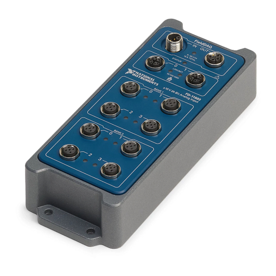
- Page 3 FD-11601 Feature Usage FD-11601 User Guide The FieldDAQ FD-11601 is an IP65/IP67-rated eight-channel simultaneous voltage input device that can be connected to external powered and TEDS sensors. It can be networked and synchronized with IEEE 802.1AS devices. Figure 1. FD-11601 Front Panel...
- Page 4 FD-11601 Feature Usage FD-11601 Basic Information Kit Contents Items in your FieldDAQ kit: FD-11601 ■ FD-11601 Quick Start ■ FD-11601 Safety, Environmental, and Regulatory Information ■ 1 M12 female cap for power IN connector (connected to device) ■ 11 M12 male caps for power OUT, Ethernet, and input connectors ■...
- Page 5 Universal M12 Female Cap, Plastic 786180-01 Universal M12 Female Cap, Metal 786179-01 FD-11960, DIN Rail Mounting Kit 786443-01 Table 2. FD-11601 Cables and Accessories Documentation Documents that contain information about your FieldDAQ device: FD-11601 Specifications ■ FD-11601 Quick Start ■ © National Instruments...
- Page 6 FD-11601 Feature Usage FD-11601 Safety, Environmental, and Regulatory Information ■ FD-11601 Calibration Procedure ■ Safety Guidelines Caution Do not operate the FD-11601 in a manner not specified in this user guide. Product misuse can result in a hazard. You can compromise the safety protection built into the product if the product is damaged in any way.
- Page 7 To avoid ESD damage in handling the device, take the following precautions: Ground yourself with a grounding strap or by touching a grounded object. ■ Touch the antistatic package to a metal part of your computer chassis ■ before removing the device from the package. © National Instruments...
- Page 8 FD-11601 Feature Usage Remove the device from the package and inspect it for loose components or any other signs of damage. Notify NI if the device appears damaged in any way. Do not install a damaged device. Store the device in the antistatic package when the device is not in use. Hardware Symbol Definitions The following symbols are marked on your FieldDAQ device.
- Page 9 1. Install the application software (if applicable), as described in the installation instructions that accompany your software. Check your driver and application development environment (ADE) readme files for specific version compatibility. 2. Install NI-DAQmx from ni.com/downloads/drivers. Complete the instructions. © National Instruments...
- Page 10 FD-11601 Feature Usage 3. Register your NI hardware online at ni.com/register when prompted. The last dialog box opens with the following options: Restart Later to install more NI software or documentation. ■ Shut Down or Restart if you are ready to install your device. ■...
- Page 11 3. Enter the hostname of the device. The default hostname is FD11601-<serial number>. Click Add Selected Devices. The FieldDAQ device icon changes from white to dark grey, indicating that it is recognized and present on the network. © National Instruments...
- Page 12 FD-11601 Feature Usage Figure 4. MAX Icons and States 1. Discovered, but Not Added to the Network 2. Recognized, Present, and Reserved on the Network 3. Recognized, but Disconnected from the Network, Unreserved, or Reserved by Another Host If your device does not appear in Available Devices, click Refresh List. If the device still does not appear, try the following: 1.
- Page 13 M12 connectors must be mated to cables or have caps installed on them to meet IP65/IP67 requirements. Cover the unused connectors with the included plastic caps whenever water, dust, or dirt are present. Note Avoid long periods of exposure to sunlight. © National Instruments...
- Page 14 FD-11601 Feature Usage For instructions on networking to a real-time controller, refer to Connecting to a Real-Time Controller. Power Connectors and Wiring The FieldDAQ device has two 5-pinL-coded M12 power connectors, power IN and power OUT. The power connectors provide one voltage line (V), one common line (C), chassis ground, and two lines for optional auxiliary power, Aux1 and Aux2.
- Page 15 Optional line for powering non-FieldDAQ devices Gray Chassis Ground. This terminal is internally connected to the C terminal. * Wire color pertains to M125F power cables sold through NI. Other manufacturers' cable wire colors may vary. Table 3. Signal Descriptions © National Instruments...
- Page 16 FD-11601 Feature Usage Power LED The green POWER LED on the front panel identifies when the device is powered. LED State Device Status Device is receiving adequate power for its tasks. Device is unpowered or receiving inadequate power. Table 4. LED State/Device Status Wiring External Power to the FieldDAQ Device Complete the following steps to connect a power source to the FieldDAQ device.
- Page 17 Voltage Input Connectors and Measurements The following figures show the voltage input circuitry and block diagram of the FD-11601. Figure 8. FD-11601 Input Circuitry Overvoltage Protection AI– Amplifier Filter Overvoltage/ Overcurrent Protection GND/T– DC/DC Converter TEDS Hardware Interface Data © National Instruments...
- Page 18 FD-11601 Feature Usage Figure 9. FD-11601 Block Diagram Ethernet Ports Ethernet Switch Synchronization Digital Logic Channel 0 Measurements Bank 1 ISOLATION Channel 3 Measurements ISOLATION Channel 0 Measurements Bank 2 ISOLATION Channel 3 Measurements Hardware Data The FD-11601 provides channel-to-channel isolation. Input signals on each channel are conditioned, buffered, and then sampled by an ADC.
- Page 19 Overload. Maximum output current exceeded for the set voltage on sensor power output. Yellow, blinking/ User-defined status. Use MAX to write a state to any LED by expanding alternating Devices and Interfaces » Network Devices » your FieldDAQ device » bank © National Instruments...
- Page 20 FD-11601 Feature Usage LED Color and State Connector Status of connectors in your FieldDAQ device and configuring the LED settings on the Settings tab. Table 6. LED State/Status Note When you turn off the LEDs in MAX, the FieldDAQ device controls and sets the state of the LED.
- Page 21 FD-11601 Specifications . When an open circuit is detected, the Open Channel status is set in NI-DAQmx and the voltage input LED turns off. © National Instruments...
- Page 22 FD-11601 Feature Usage If a connected sensor draws a total current below the maximum specifications values, the voltage input LED lights green. Connecting TEDS Sensors You can connect TEDS (Transducer Electronic Data Sheets) sensors to the FieldDAQ device through the T+ and T- pins on each connector. Figure 15.
- Page 23 How the filter discriminates signals based on their frequency is known as frequency response. In general, the frequency response of a filter is described by a signal attenuation (magnitude response) and an input delay (phase response) for every input frequency. © National Instruments...
- Page 24 FD-11601 Feature Usage Magnitude Response—The three important frequency ranges, or ■ bandwidths, to consider for magnitude response are passband, transition band, and stopband: Figure 16. Example Magnitude Response of a Lowpass Filter Frequency (Hz) Passband—The range of frequencies at which the filter attempts to pass a ■...
- Page 25 The comb filter's transition band features equally-spaced notches at different frequencies. It is common to use the comb filter with a specific sample rate to align the notches of the transition band thereby removing a specific noise-source frequency from measurements. © National Instruments...
- Page 26 FD-11601 Feature Usage Figure 18. Comparing Typical Magnitude Response of FieldDAQ Filters Brickwall Butterworth –20 Comb –40 –60 –80 –100 –120 –140 –160 Frequency (Hz/f The FieldDAQ filters vary between input delay across signals in the passband: Brickwall—All input frequencies have the same amount of delay when going ■...
- Page 27 Figure 20. Comparing Typical Step Response of FieldDAQ Filters Overshoot Rise Time Brickwall Butterworth Group Delay Undershoot Comb Time Refer to the FD-11601 Specifications for details on the amount of variation in the response you can expect for different input frequency ranges. © National Instruments...
- Page 28 FD-11601 Feature Usage Data Rates You can use the 13.1072 MHz, 12.8 MHz, 12.288 MHz, and 10.24 MHz timebases to generate data rates. The FD-11601 supports data rates (f ) between 500 Samples/s and 102.4 kSamples/s. By default, NI-DAQmx automatically chooses the most suitable timebase for a selected data rate.
- Page 29 AI.Filter.Freq (Channel:Analog Input:General Properties:Filter:Frequency)— ■ Range of values for Butterworth filters are 100 to 4096. NI-DAQmx rounds up to the nearest supported cutoff frequency for the timebase used. Read this property to get the actual cutoff frequency used: © National Instruments...
- Page 30 FD-11601 Feature Usage Brickwall filter—Returns the stopband frequency (one-half the sample ■ rate) Comb filter—Returns the first notch frequency (equal to the sample rate) ■ You do not need to specify the filter frequency with Brickwall or Comb filters. NI-DAQmx returns an error if you specify a frequency higher than the frequency that would otherwise be returned.
- Page 31 Conditioning:Bridge:Shunt Cal:Gain Adjustment). You can read this property to see the amount of correction being applied as a result of the shunt calibration. Note You must use the DAQmx Perform Bridge Offset Nulling Calibration function immediately prior to using the DAQmx Perform Shunt Calibration © National Instruments...
- Page 32 FD-11601 Feature Usage function because the Shunt Calibration uses the result of the Offset Nulling calibration as the unshunted value. Directly Programming the Shunt Calibration Switch With quarter bridge configurations, you may also directly control the internal shunt calibration resistor by writing to the NI-DAQmx Channel property AI.Bridge.ShuntCal.Enable (Channel:Analog Input:General Properties:Signal Conditioning:Bridge:Shunt Cal:Shunt Cal Enable).
- Page 33 The simplest method for starting all the tasks at the same point in time is to set the NI-DAQmx Timing property FirstSampClk.When (Timing:Advanced:First Sample Clock Time:When). NI-DAQmx configures the necessary timing and triggering signals © National Instruments...
- Page 34 FD-11601 Feature Usage to ensure that the first sample clock on every device occurs simultaneously at the time you write to this property. Even though the channels are all sampled simultaneously, the sampled data represents the signal present at the input terminals at an earlier time due to the input delay of the signal through the filtering of the channel.
- Page 35 The 13.1072 MHz, 12.8 MHz, 12.288 MHz, and 10.24 MHz timebases are all synchronized to each other and are automatically synchronized to other network- synchronized devices that are part of your local IEEE 802.1AS subnet. This enables © National Instruments...
- Page 36 FD-11601 Feature Usage measurement signals to be synchronized to other devices across a distributed network. Figure 21. AI Sample Clock Timebase Options 13.1072 MHz Timebase AI Sample Clock AI Sample Timebase Clock 12.8 MHz Timebase Programmable Network Clock Divider 12.288 MHz Timebase Synchronized Clock 10.24 MHz Timebase...
- Page 37 Figure 23. Relationship of Timing and Triggering Signals Sync Pulse Earliest Allowed Time for AI Start Trigger Reset Time AI Start Trigger Earliest Possible AI Sample Clock AI Sample Clock AI Sample Clock Input Delay Input Signal Returned Sampled Data Point © National Instruments...
- Page 38 FD-11601 Feature Usage You can configure the Start Trigger signal to occur at a specific time by writing to the DAQmx property Start.Time.When (Trigger:Start:Time:When). Refer to Time-Based Triggers for more information about specifying time events. Analog Input Sync Pulse The Analog Input Sync Pulse resets the internal generation of the Sample Clock signal.
- Page 39 DAQmx Trigger node in LabVIEW, or the DAQmxCfgTimeStartTrig function in C. Note You must set the start trigger to occur after the synchronization pulse by at least the reset time, ss described in AI Start Trigger Signal. © National Instruments...
- Page 40 FD-11601 Feature Usage Time triggers can be specified in Host Time or I/O Device Time, depending on the needs of your application. I/O Device Time—The time the FieldDAQ device uses internally. This ■ time is determined by the network configuration and is shared by all IEEE 802.1ASnetwork-synchronized devices on your subnet.
- Page 41 For an example of synchronizing with this IEEE 1588 profile, see the tutorial “Synchronizing FieldDAQ and TSN-Enabled Ethernet cDAQ Chassis to a PXI System” by visiting ni.com/info and entering fd1588. More Information about Synchronization The following documents will help you overcome typical hurdles in getting started with synchronized measurements: © National Instruments...
- Page 42 FD-11601 Feature Usage Synchronizing analog input FieldDAQ devices with NI-DAQmx in LabVIEW ■ —Visit ni.com/info and enter fdaisync. Designing Ethernet measurement systems for synchronization, considering ■ topologies, masters, and third party devices—If topology changes result in a device’s master changing, executing tasks may be affected. Visit ni.com/info and enter fdenet.
- Page 43 Each Ethernet port has a green LED that indicates network activity and link speed. LED State Device Status Ethernet link Blinking, fast (12 blinks/s) Ethernet activity. Connected at 1,000 Mbit/s. Blinking, moderate (6 blinks/s) Ethernet activity. Connected at 100 Mbit/s. Blinking, slow (3 blinks/s) Ethernet activity. Connected at 10 Mbit/s. © National Instruments...
- Page 44 FD-11601 Feature Usage LED State Device Status No Ethernet connection Table 11. LED State/Device Status Internal Ethernet Switch The FieldDAQ device features a full hardware-accelerated internal Ethernet switch for greater performance, wiring flexibility, and compatibility over standard Ethernet ports. The Ethernet switch exposes two Ethernet ports to the user. Either port can be used to connect the device to the network.
- Page 45 IP address Used by normal device traffic Used for Ethernet protocols for network configuration and synchronization Listed in MAX Not listed in MAX Table 10. NI MAX Device and Switch MAC Addresses © National Instruments...
- Page 46 FD-11601 Feature Usage The switch MAC address is used to implement the following switch protocols: IEEE 802.1AS-2011 (Precision Time Protocol) ■ IEEE 802.1Q (Rapid Spanning Tree Protocol [RSTP]) ■ IEEE 1588-2008 (Precision Time Protocol) ■ The switch MAC address only appears in packets exchanged between the switch embedded in the FieldDAQ device and the next Ethernet device.
- Page 47 You must use an external switch in a ring topology. You must configure the network properly with a recommended external switch before creating redundant links in the network. Refer to External Switch Requirements for information about what to look for in an external switch. © National Instruments...
- Page 48 FD-11601 Feature Usage Figure 28. Ring Topology Host Node Node Node External Networking Switch Advantages: Failure of any single Ethernet cable does not disrupt network ■ communication Additional nodes or heavier network traffic affects network performance ■ less than the line topology Simple installation ■...
- Page 49 Disadvantages: Most costly of the recommended topologies ■ Requires an external switch (external IEEE 802.1AS switch for network ■ synchronization) Covers the least distance ■ © National Instruments...
- Page 50 FD-11601 Feature Usage Note For information about daisy-chaining power, refer to Power Connectors and Wiring. Other Topologies For information about designing Ethernet measurement systems for synchronization, visit ni.com/info and enter fdenet. External Switch Requirements To meet the minimum requirements for successful operation with FieldDAQ devices, any switch directly connected to the FieldDAQ device should be compliant with IEEE 802.1Q bridges and bridged networks.
- Page 51 NI Linux Real-Time operating system that support NI-DAQmx. Supported NI Linux Real-Time controllers include the IC-317x, cRIO-9035/9039 Sync, cRIO-904x/905x, and cDAQ-9132/9133/9134/9135/9136/9137 for LabVIEW Real-Time. To network the FieldDAQ device to a Real-Time controller, you need the following items. © National Instruments...
- Page 52 FD-11601 Feature Usage Figure 1. FieldDAQ Installation Supply List NI-DAQmx 1. Host Computer 2. Supported Real-Time Controller 3. LabVIEW Software, if not already installed 4. LabVIEW Real-Time Module, if not already installed 5. Driver for the Real-Time Controller, if not already installed 6.
- Page 53 7. Power the device by aligning and connecting the power IN port on FieldDAQ to an external 9 V DC to 30 V DC power source with the 5-pinL-coded M12 power cable. For information about wiring your external power source to © National Instruments...
- Page 54 FD-11601 Feature Usage the power connector, refer to Wiring External Power to the FieldDAQ Device. The FieldDAQ device requires an external power supply that meets the specifications listed in the FD-11601 Specifications . The Power LED turns on. Refer to Power LED for information about Power LED status.
- Page 55 This is normal. Note M12 connectors must be mated to cables or have caps installed on them to meet IP65/IP67 requirements. Cover the unused connectors with the included plastic caps whenever water, dust, or dirt are present. © National Instruments...
- Page 56 FD-11601 Feature Usage Note Avoid long periods of exposure to sunlight. Troubleshooting Device Connectivity If your FieldDAQ device becomes disconnected from the network, open MAX and try the following: After moving the device to a new network, NI-DAQmx may lose connection ■...
- Page 57 Resetting the FieldDAQ to Factory-Default Settings To reset your FieldDAQ device to factory-default settings, complete the following steps. 1. Verify the power source is turned off. 2. Connect Ethernet port 0 and port 1 with an Ethernet cable. © National Instruments...
- Page 58 FD-11601 Feature Usage Figure 33. Connecting Port 0 and Port 1 LINK/ACT 10/100/1000 SYNC 3. Turn on the power source to the device. After about 15 seconds, the STATUS LED blinks red indicating that the device has been restored to factory-default settings.
- Page 59 Before using any mounting methods, record the serial number from the back of the FieldDAQ device so that you can identify it in MAX. You will be unable to read the serial number after you mount the device. © National Instruments...
- Page 60 FD-11601 Feature Usage Mounting Requirements Your installation must meet the following requirements for cooling and cabling clearance. Allow 76.2 mm (3.00 in.) on all sides of the device for air circulation, as shown in the following figure. Figure 35. Cooling Dimensions FieldDAQ 9-30 V 10 A TOTAL...
- Page 61 76.2 mm (3.00 in.) 76.2 mm (3.00 in.) 99.3 mm (3.90 in.) Measure the ambient Measure the ambient temperature here temperature here 25.4 mm 76.2 mm 76.2 mm 25.4 mm (1.00 in.) (3.00 in.) (3.00 in.) (1.00 in.) © National Instruments...
- Page 62 FD-11601 Feature Usage Dimensions For detailed dimensional drawings and 3D models, visit ni.com/dimensions search for FD-11601. Mounting the Device Directly on a Flat Surface For environments with high shock and vibration, NI recommends mounting the FieldDAQ device directly on a flat, rigid surface using the mounting holes on the device.
- Page 63 DIN rail. The hardware in the FD-11960 DIN rail mounting kit includes a bracket panel, a DIN rail clip, four M5 x 10 mm screws, four M5 washers, and two 8-32 x 1/4 in. screws. © National Instruments...
- Page 64 FD-11601 Feature Usage Complete the following steps to install a FieldDAQ device onto a DIN rail using the FD-11960 DIN rail mounting kit. 1. Attach the FieldDAQ device to the bracket panel using the included M5 x 10 mm screws and M5 washers. The front of the bracket panel, which includes an outline of the FieldDAQ device, should be attached to the back of the FieldDAQ device.
- Page 65 Figure 42. DIN Rail Clip Parts Locator 1. DIN rail clip 2. DIN rail spring 3. DIN rail Figure 43. FD-11960 Dimensions 101.6 mm (4.0 in.) FieldDAQ 9-30 V 10 A TOTAL STATUS LINK/ACT 10/100/1000 SYNC 228.6 mm (9.0 in.) © National Instruments...
- Page 66 FD-11601 Feature Usage Calibration The FD-11601 can be verified and adjusted. Refer to the FD-11601 Calibration Procedure for a detailed calibration procedure. Ensure that your driver software is updated to a version that supports calibration for your FieldDAQ device. Driver Earliest Version Support NI-DAQmx 19.0...
- Page 67 The FD-11601 Safety, Environmental, and Regulatory Information , packaged with your device, includes important compliance precautions and connection information for your FieldDAQ device. The FD-11601 Calibration Procedure contains information for calibrating your FieldDAQ device. Go to ni.com/manuals and search for FD-11601. © National Instruments...
- Page 68 FD-11601 Feature Usage NI-DAQmx The NI-DAQmx Readme lists which devices, ADEs, and NI application software are supported by this version of NI-DAQmx. Select Start » All Programs » National Instruments » NI-DAQmx » NI-DAQmx Readme. The NI-DAQmx Help contains API overviews, general information about measurement concepts, key NI-DAQmx concepts, and common applications that are applicable to all programming environments.
- Page 69 Data Acquisition. This book also contains information about accessing detailed information through the NI-DAQmx Help. The NI-DAQmx Library book of the LabWindows/CVI Help contains API overviews and function reference for NI-DAQmx. Select Library Reference » NI-DAQmx Library in the LabWindows/CVI Help. © National Instruments...
- Page 70 You can use the NI-DAQmx .NET class library to communicate with and control an NI data acquisition (DAQ) device. Documentation for the NI-DAQmx .NET class library is available by selecting Start » All Programs » National Instruments » NI-DAQmx » NI-DAQmx Documentation and then opening the NINETDAQmxFxXX.chm help file corresponding to the version of NI-DAQmx .NET Framework language support you...
- Page 71 ANSI C without NI Application Software The NI-DAQmx Help contains API overviews and general information about measurement concepts. Select Start » All Programs » National Instruments » NI- DAQmx » NI-DAQmx Help. The NI-DAQmx C Reference Help describes the NI-DAQmx Library functions, which you can use with National Instruments data acquisition devices to develop instrumentation, acquisition, and control applications.
- Page 72 FD-11601 Feature Usage The cDAQ-9138/9139 for LabVIEW Real-Time controllers will not work in this configuration. ni.com © 2022 National Instruments Corporation.
Need help?
Do you have a question about the FieldDAQ FD-11601 and is the answer not in the manual?
Questions and answers