Table of Contents
Advertisement
Quick Links
Installation & Service Instructions
Combi 30 HE
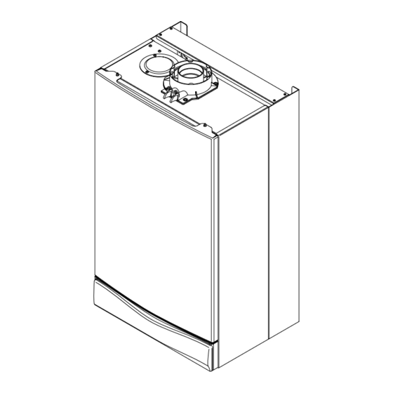
This is a Wall Mounted Powered Flue Condensing Combination Boiler Gas Fired
Central Heating Unit.
The boiler meets the requirements of Statutory Instrument " The Boiler (Efficiency)
Regulations 1993 N
o
3083" and is deemed to meet the requirements of Directive
92/42/EEC on the energy efficiency requirements for new hot water boilers fired
with liquid or gaseous fuels:-
Type test for purpose of Regulation 5 certified by:
Notified Body 0051.
Product/Production certified by:
Notified Body 0086.
For use in GB/IE only.
These instructions include the Benchmark Commissioning Checklist and should be
left with the User for safe keeping.
Advertisement
Table of Contents

Related Manuals for Main Combi 30 HE


Summary of Contents for Main Combi 30 HE
- Page 1 Installation & Service Instructions Combi 30 HE This is a Wall Mounted Powered Flue Condensing Combination Boiler Gas Fired Central Heating Unit. The boiler meets the requirements of Statutory Instrument “ The Boiler (Efficiency) Regulations 1993 N 3083” and is deemed to meet the requirements of Directive...
-
Page 2: Table Of Contents
Natural Gas Building Regulations and the Benchmark Commissioning Checklist Main Combi 30 HE G.C.N 47 474 03 Building Regulations (England & Wales) require notification of the installation of a heating appliance to the relevant Local Authority Building Control Department. From 1 April 2005 this can be achieved via... - Page 3 INSTALLER NOTIFICATION GUIDELINES Install and Commission this appliance to manufacturer's instructions Complete the Benchmark Checklist Choose Building Regulations Notification Route Competent Person's Building Control Self Certification Scheme If you notify via CORGI Scheme, Contact your relevant Local CORGI will then notify the Authority Building Control relevant Local Authority (LABC) who will arrange...
-
Page 4: Legislation
LEGISLATION IMPORTANT - Installation, Commissioning, Service & Repair Baxi Potterton declare that no substances harmful to health are contained in the appliance or used This appliance must be installed in accordance with the manufacturer’s during appliance manufacture. instructions and the regulations in force. Read the instructions fully before installing or using the appliance. -
Page 5: Introduction
INTRODUCTION Description 1. The Main Combi 30 HE is a fully automatic gas fired wall mounted condensing combination boiler. It is room sealed and fan assisted, and will serve central Case Front Panel heating and mains fed domestic hot water. -
Page 6: General Layout
GENERAL LAYOUT Layout Air Pressure Switch Expansion Vessel Burner Manifold Automatic Air Vent DHW Plate Heat Exchanger Circulation Pump Drain Off Point Pressure Relief Valve Optional Integral Timer Position Central Heating System Pressure Gauge Control Box 3-Way Valve Assembly Condensate Trap Flame Sensing Electrode Spark Electrode Burner... -
Page 7: Appliance Operation
At a pre- determined flow rate the central heating flow switch operates, initiating the ignition sequence. 2. The main burner ignites at low rate, then the gas valve controls the gas rate to maintain the heating temperature measured by the temperature sensor. -
Page 8: Technical Data
32.3 ± 0.5 5.2 ± 0.2 Inlet Pressures mbar SEDBUK Declaration For Combi 30 HE The seasonal efficiency (SEDBUK) is 87.3% (89.4% LPG) Band B This value is used in the UK Government’s Standard Assessment Procedure (SAP) for energy rating of dwellings. The test data from... -
Page 9: Dimensions And Fixings
DIMENSIONS AND FIXINGS Dimensions A 780mm B 345mm C 450mm D 116mm Ø Min. E 185mm F 190mm G 131mm 360° Orientation Tube Ø 100mm Tap Rail 28mm Condensate Drain 65 mm 65 mm 65 mm 65 mm 65 mm Heating Heating Domestic Hot... -
Page 10: System Details
SYSTEM DETAILS Information 1. The Main Combi 30 HE Condensing Combination Boiler is a ‘Water Byelaws Scheme - Approved Product’. To comply with the Water Byelaws your attention is drawn to the following installation requirements and notes (IRN). a) IRN 001 - See text of entry for installation requirements and notes. - Page 11 SYSTEM DETAILS System Filling and Pressurising 1. A filling point connection on the central heating return pipework must be provided to facilitate initial filling and pressurising and also any subsequent water loss replacement/refilling. Double Stop Stop 2. There are connection points on the mains cold Check Valve Valve...
- Page 12 SYSTEM DETAILS Other Tap Domestic Hot Water Circuit (Fig. 7) Outlets 1. All DHW circuits, connections, fittings, etc. should Boiler Expansion be fully in accordance with relevant standards and Vessel water supply regulations. 2. Your attention is drawn to: for GB: Guidance G17 to G24 and recommendation Check R17 to R24 of the Water Regulations Guide.
-
Page 13: Site Requirements
SITE REQUIREMENTS 20mm/5mm Min Location 5mm Min 450mm see *NOTE: 1. The boiler may be fitted to any suitable wall with the flue passing through an outside wall or roof and discharging to atmosphere in a position permitting 200mm Min satisfactory removal of combustion products and providing an adequate air supply. - Page 14 SITE REQUIREMENTS Ventilation of Compartments 1. Where the appliance is installed in a cupboard or compartment, no air vents are required. 2. BS 5440: Part 2 refers to room sealed appliances installed in compartments. The appliance will run sufficiently cool without ventilation. Gas Supply 1.
- Page 15 SITE REQUIREMENTS Condensate Drain Termination to an internal soil Boiler FAILURE TO INSTALL THE CONDENSATE DISCHARGE and vent pipe PIPEWORK CORRECTLY WILL AFFECT THE RELIABLE OPERATION OF THE BOILER The condensate discharge pipe MUST NOT RISE at any point along its length. There MUST be a fall of AT LEAST 2.5°...
- Page 16 SITE REQUIREMENTS Flue NOTE: Due to the nature of the boiler a plume of water vapour will be discharged from the flue. This should be taken into account when siting the flue terminal. 1. The following guidelines indicate the general requirements for siting balanced flue terminals.
- Page 17 SITE REQUIREMENTS Flue Dimensions The standard horizontal flue kit allows for flue lengths between 100mm and 685mm from elbow to terminal (Fig. 13). The maximum permissible equivalent flue length 3 metres Flue Trim 1. The rubber flue trim supplied may be fitted to either the outside wall or on the inner wall of Fig.
- Page 18 SITE REQUIREMENTS 7.11 Flue Options 1. The Main Combi 30 HE can be fitted with flue systems as illustrated. 2. The standard flue is suitable only for horizontal applications. 3. Maximum permissible equivalent flue lengths are:- Horizontal Concentric 3metres Vertical Concentric...
-
Page 19: Installation
INSTALLATION Initial Preparation The gas supply, gas type and pressure must be checked for suitability before connection (see Section 7.4). 1. After considering the site requirements (see Section 7.0) position the fixing template on the wall ensuring it is level both horizontally and vertically. - Page 20 Wall Plate INSTALLATION Fitting The Boiler 1. Remove the sealing caps from the boiler connections. 2. Lift the boiler using the lower edges. Engage the slots at the top rear of the boiler on the wall plate (Fig. 18). 3. Insert the sealing washers between the valves and pipes on the wall plate and the boiler connections.
- Page 21 INSTALLATION Fitting The Flue HORIZONTAL FLUE 1. The standard flue is suitable for lengths between 100mm minimum and 685mm maximum, as measured from the edge of the flue elbow outlet to the joint between the terminal and air duct (Fig. 20). 2.
- Page 22 11. Fit the flue trim if required, and if necessary fit a terminal guard (see Section 7.9 & 7.10). VERTICAL FLUE 1. Only a flue approved with the Main Combi 30 HE can be used. Flue Trim Fig. 25...
- Page 23 INSTALLATION Making The Electrical Connections To connect the mains input cable proceed as follows:- 1. Slacken the facia panel securing screws and lift the outercase panel so that its securing tabs are clear of the facia. Remove the panel. Control Box Cover 2.
-
Page 24: Commissioning
COMMISSIONING Commissioning the Boiler 1. Reference should be made to BS 5449 Section 5 Screw when commissioning the boiler. 2. Open the mains water supply to the boiler. 3. Open all hot water taps to purge the DHW system. Automatic Air Vent 4. - Page 25 COMMISSIONING Checking the Burner Pressure Pressure Test Point 1. Turn on the gas and electrical supplies to the Sealing Screw boiler and ensure that all external controls are calling for heat. 2. Set the temperature controls to maximum and the selector switch to the Off position (Fig.
-
Page 26: Completion
10.0 COMPLETION 10.1 Completion Case Front Panel 1. Hinge the facia panel upwards and refit the case front panel. Tighten the securing screws (Fig. 38). 2. Instruct the user in the operation of the boiler and system, explaining the operational sequence. 3. -
Page 27: Servicing
11.0 SERVICING 11 .1 Annual Servicing Case Front Panel 1. For reasons of safety and economy, it is recommended that the boiler is serviced annually. Servicing must be performed by a competent person. 2. After servicing, complete the relevant Service Interval Record section of the Benchmark Commissioning Checklist at the rear of this publication. - Page 28 11.0 SERVICING Baffle 11.1 Annual Servicing (Cont) Spring Clip 11. Ease the front edge of the left hand baffle upwards, disengaging the spring clip. Disengage the tab on the baffle from the slot in the fan hood (Fig. 42). 12. Undo the screws securing the fan and hood to the appliance back panel.
-
Page 29: Changing Components
12.0 CHANGING COMPONENTS IMPORTANT: When changing components ensure that both the gas and electrical supplies to Pressure the boiler are isolated before any work is started. Switch When the component has been changed turn the selector switch fully anticlockwise against the spring pressure to the reset position and hold for Sensing 2 seconds to reset the boiler before... - Page 30 12.0 CHANGING COMPONENTS 12.3 Heat Exchanger (Fig. 50) 1. Remove the fan as described in section 12.1. 2. Drain the primary circuit. Prise the three pipe connecting clips off the joints in the flow and return pipes. Remove the heat exchanger return pipe. Pipe Connecting Clips 3.
- Page 31 12.0 CHANGING COMPONENTS 12.5 Injectors (Fig. 52) Injector Inlet Elbow Manifold 1. Remove the burner as described in Section 12.4. 2. Undo the screws securing the injector manifold to the inlet elbow and remove the manifold. Gasket 3. Unscrew and replace injectors as required and examine the sealing gasket, replacing as necessary.
- Page 32 12.0 CHANGING COMPONENTS 12.8 Gas Valve (Fig. 54) 1. Undo the nut on the gas feed pipe under the boiler. Modulator 2. Completely undo the securing screws and hinge Wires the facia panel down. Ignition 3. Disconnect the wires from the valve modulator Lead Gas Valve and the ignition lead from the spark generator.
- Page 33 12.0 CHANGING COMPONENTS 12.12 Pump - Head Only (Fig. 57) 1. Drain the primary circuit and remove the socket head screws securing the pump head to the body and draw the head away. 2. Undo the screw on the pump wiring cover and remove the cover.
- Page 34 12.0 CHANGING COMPONENTS 12.15 Pressure Gauge (Figs. 60 & 61) 1. Drain the primary circuit and undo the nut on the pressure gauge capillary. 2. Remove the timer cover and ease the timer wiring aside. Undo the screws securing the gauge retaining Fig.
- Page 35 12.0 CHANGING COMPONENTS 12.18 Pressure Relief Valve (Fig. 64) 1. Drain the primary circuit. 2. Disconnect the discharge pipe from the valve. Using a suitable hexagon key undo the grub screw sufficiently to release the valve. 3. Note the orientation of the valve, rotate it and withdraw it from the manifold.
- Page 36 12.0 CHANGING COMPONENTS 12.21 Plate Heat Exchanger (Fig. 67) Plate Heat Exchanger 1. Drain the primary circuit. 2. While supporting the heat exchanger undo the screws securing it to the brass manifolds. 3. Withdraw the heat exchanger upwards and to the left of the gas valve, taking care not to damage any wires or controls.
- Page 37 12.0 CHANGING COMPONENTS 12.22 Diverter Valve Assembly (Cont) Central Heating Pressure Pressure Differential Valve (Fig. 70) Differential Valve Microswitch / 1. Remove the pressure differential valve as described above. Sensing Pipe 2. From the brass diverter manifold undo the nut on the heating flow pipe.
- Page 38 12.0 CHANGING COMPONENTS 12.24 Secondary Heat Exchanger) (Fig. 73) Recuperator 1. Drain the primary circuit Heat Exchanger 2. Undo the four screws securing the right hand case Pipe Connecting Clip panel. Remove the panel. 3. Prise the connecting clips from the heat exchanger Fan Spigot return pipe and the boiler return pipe.
-
Page 39: Electrical
13.0 ELECTRICAL 13.1 Illustrated Wiring Diagram Air Pressure Switch Central Heating Temperature Sensor Domestic Hot Water Temperature Sensor Domestic Hot Water Flow Priority Pressure Switch Hydraulic Differential Pressure Switch Pump Control PCB Flame Sensing Electrode Mains Input Link Fuse Overheat Stat Flue Stat Gas Valve Condensate... -
Page 40: Short Parts List
14.0 SHORT PARTS LIST Short Parts List G.C. Description Manufacturers Part No. 5112430 Pressure Switch 248466 Heat Exchanger 5112431 Burner 5112770 Injector 5112376 E66 408 Electrode Lead 248037 E66 411 Spark or Sensing Electrode 247384 E66 539 Pump (complete) 248042 E66 432 3-Way Valve Assy. -
Page 41: Fault Finding
14.0 FAULT FINDING Carry out initial fault finding checks 1. Check that gas, water and electrical supplies are available at the boiler. Electrical supply = 230V ~ 50 Hz. CH water system pressurised to 0.5 bar when the boiler is cold. The preferred minimum gas pressure is 19.5mbar (natural gas), or 36mbar (propane). - Page 42 14.0 FAULT FINDING Domestic Hot Water - Follow operational sequence Turn selector to Replace diaphragm Go to section ‘A’ neon illuminated Is mains water DHW flow valve filter and differential diaphragm damaged assembly clean? Turn thermostat to DHW flow rate more than DHW flow valve rod max.
- Page 43 14.0 FAULT FINDING Fault Finding Solutions Sections A to E Is there 230V at: Check electrical supply Main terminals L and N Main terminal fuse Replace fuse neon Replace PCB illuminated Selector terminals a & b Check wiring and a & 3. PCB - A4 Replace selector connector terminals 4 &...
- Page 44 Replace PCB 30 ÷ 230 mA DC (45 ÷ 310 mA DC LPG) Check and correct if necessary Replace PCB 230V at Main PCB - A1 1. Ignition electrode and lead connector across terminals 2. Electrode connection Replace gas valve 3 &...
- Page 45 14.0 FAULT FINDING Ensure that mains input terminal L is Live (230V) and N is Neutral (0V) Check and correct if necessary 1. Flame sensing electrode and lead connections 2. Electrode position Replace PCB Flame current should be 1 µA approx. Replace flame sensing electrode Overheat thermostat operated Allow to cool.
-
Page 46: Benchmark Checklist
5 1 1 5 8 1 0 BENCHMARK No. GAS BOILER COMMISSIONING CHECKLIST C O L L E C T I V E M A R K BOILER SERIAL No. NOTIFICATION No. CONTROLS To comply with the Building Regulations, each section must have a tick in one or other of the boxes TIME &... - Page 47 SERVICE INTERVAL RECORD It is recommended that your heating system is serviced regularly and that you complete the appropriate Service Interval Record Below. Service Provider. Before completing the appropriate Service Interval Record below, please ensure you have carried out the service as described in the boiler manufacturer’s instructions.
- Page 48 - Iss. 2 Publication No. 5115810 (03/2006) General Enquiries (GB) 08706 060 780 Tel. Technical (GB) 08706 049 049 Tel. Service (GB) 08701 655 644 Tel. 01926 410 006 Fax. Literature Request (GB) 08706 060 623 Tel. Technical (IE) 1850 560570 Tel.
- Page 49 User’s Guide and Combi 30 HE Important Warranty Information This is a Wall Mounted Powered Flue Condensing Combination Boiler Gas Fired Central Heating Unit. The boiler meets the requirements of Statutory Instrument “ The Boiler (Efficiency) Regulations 1993 N 3083” and is deemed to meet the requirements of Directive...
- Page 50 Natural Gas Dear User Main Combi 30 HE Thank you for choosing a Main Combination boiler. The G.C.N 47 474 03 following instructions are simple basic steps that you can take to ensure years of trouble free heating and hot water for your home.
- Page 51 OFF Position 7. The orange burner on neon ( ) will illuminate Position (i) when the boiler is operating and the main burner is (Central Heating or Hot Water) on (Fig. 2). IMPORTANT: When the selector switch is in the ‘0’...
- Page 52 Facia Panel 1. The facia panel is behind the hinged lower door panel. As well as the on/off/reset selector switch, temperature control knobs and pressure gauge, the facia incorporates ten neon indicator lights. 2. Neons 12 to 15 indicate the operational status of the boiler.
- Page 53 Service Engineer should be contacted as soon as possible. Safety Thermostat Fig. 9 1. Your Main Combi 30 HE is fitted with additional safety devices, which shut down the boiler in the event of the system, the boiler or the flue overheating. The safety thermostat neon ( ) will light in this instance (Fig.
- Page 54 Air Flow Monitor 1. The boiler is fitted with an air pressure sensing device. This monitors the flue system. Pump/Low Sensor Fault Pressure Neon 2. If the neon illuminates ( ) it indicates that the Neons flue or flue terminal is blocked or obstructed in Air Flow Monitor Neon some way, or that there is an internal fault.
- Page 55 Central Heating System Pressure 1. The water pressure in the central heating Pressure Gauge system is indicated by the pressure gauge. 2. With the system cold and the boiler not operating the pressure should be between 0.5 and 1.0 bar. During operation the pressure should not exceed 2.5 bar, and will normally be between 1.0 and 2.0 (Figs.
- Page 56 Servicing and Repair of your Boiler heateam can service and repair your boiler if your installer is not able to. Our Baxi Potterton trained heating experts will quickly get your heating and hot water working again. If your boiler is out of its free 12 month period, heateam can provide a competitive fixed price repair rate including parts, labour and VAT.
- Page 57 For your Safety 20mm/5mm Min see *NOTE: 5mm Min 450mm This appliance must have been installed in accordance with the manufacturer’s instructions and the regulations in force. Any modification that may interfere with the normal 200mm Min operation of the appliance without express written permission from the manufacturer or his agent could invalidate the appliance warranty.
- Page 58 In the unlikely event you have a problem with your boiler please check the following. 1. Is the electricity supply to your boiler switched on No Heating/Hot Water and the selector switch set to Central Heating Hot Water? If so the Green ‘Power On’ neon will be on. 2.
- Page 59 Warning ! If you smell gas Turn off the gas supply at the meter and call your gas supplier immediately. It is possible to isolate the boiler and at the isolating valve (Fig. 21). In GB, Transco operate a 24 hour emergency service and the telephone number will be listed in your telephone directory.
- Page 60 5115814 - Iss. 2 Publication No. (03/2006) heateam heateam is the national customer service division of Please complete the boxes below Baxi Potterton providing a free warranty service within 12 months of installation of your boiler. If your installer Serial Number is unable to rectify your boiler fault, by contacting one of our friendly advisors we can arrange an engineer if required.
Need help?
Do you have a question about the Combi 30 HE and is the answer not in the manual?
Questions and answers